Available Online at www.ijpret.com
307
INTERNATIONAL JOURNAL OF PURE AND
APPLIED RESEARCH IN ENGINEERING AND
TECHNOLOGY
A PATH FOR HORIZING YOUR INNOVATIVE WORKSTRUCTURAL PERFORMANCE ANALYSIS OF FORMULA SAE CAR
PIYUSH RAM SHAHADE1, AKSHAY KUMAR KAWARE2
1. Final Year Mechanical Engineering, Jawaharlal Darda Institute of Engineering and Technology, Yavatmal, India.
2. Final Year Mechanical Engineering, Jawaharlal Darda Institute of Engineering and Technology, Yavatmal, India.
Accepted Date: 27/02/2014 ; Published Date: 01/05/2014
\
Abstract: SAE Supra India organizes the undergraduate racing completion for 2013 in which teams are challenged to design considering the various circumstances and to fabricate the created design in the camps itself. This paper’s sole focus is the design and analysis for a chassis which has to sustain the racing environment. As chassis plays a vital role in a race car but can be called as the back bone of a good race car. Good designs allow a light, stiff and extremely safe chassis to be produced at a reasonable manufacturing cost. The work shown in this research paper was taken participation by Black Hawk SAE Supra team. This paper introduces several concepts of frame’s load distributions such a lateral, longitudinal vertical and horizontal torsion and consequent deformation modes. .Various studies were conducted upon the understanding the relation of the machine elements with the driver (Ergonomics).Ergonomics considers factors such as Drivers visibility, seat inclination, thermal isolation etc.The chassis design was carried out on CAD software Pro-Engineers. Design model was prepared using anthropometric parameters of tallest driver as 95th percentile male was selected to SAE rules book and previous design knowledge. Static and dynamic load distributions were calculated analytically followed by extensive study of various boundary conditions to be applied during diverse FEA (Finite Element Analysis) test which was carried out in Ansys. Stress distributions, lateral displacements during static, dynamic and frequency modes were analyzed and found considerably high factor of safety as 3.85
Keywords: Supply Chain Management, Quality Management System, Factor Analysis
Corresponding Author: MR. PIYUSH RAM SHAHADE
Access Online On:
www.ijpret.com
How to Cite This Article:
Piyush Ram Shahade, IJPRET, 2014; Volume 2 (9): 307-320
Available Online at www.ijpret.com
308
INTRODUCTION
SAE (society of automotive engineers ) has conduct the competition in which student build, design, and compete with a small formula race car .these compensation help in providing the educational experience that analogous to the type of project work they will face in work force ,it also help the student to participate in group work ,project management and finance have been incorporated in the rules of SAE. The SAE competition is consisting of static and dynamic event where they are judge on the performance of vehicle. The main philosophy behind the impact test is that to assure the driver safety in the survival cell the survival cell should be strong enough to absorb the force and to distribute the force from front to the back without large deflection to the chassis. The chassis should be strong enough to absorb the energy when front, back, side, torsional are the load which occur during the impact test should be distributed progressively. These paper give the introduction of the various frame design concept and provide analytical and the experimental both. The various loading condition are also describe below.
These paper is consist of various test whish are conduct on the chassis which give the detail description are documented below. Which are such as front impact test, side impact test, roll over test, torsional test these are the test which are conducted. The paper has also provide the detail description of the material which is used while design of the vehicle these has widen the structure strength and modeled the design to inculcate more driver comfort ,safety the structure is in the truss form which help to reduce the energy in structure.
The mode of load distribution and the concept were taken from the various books and the reference
TYPES OF CHASSIS
The chassis is the back bone of the vehicle, all component such as transmission system, engine, fuel tank, steering system, suspension system etc are mounted on the chassis .there are different material which are used for the manufacturing of the chassis .the material is selected according to their cost and properties required for the vehicle, the car are influential by the car weight such as carbon fiber which is light in weight.
The chassis are classified as:
Available Online at www.ijpret.com
309
(iii) Full forward control chassis: in these types of the chassis the engine is mounted completely inside driver’s cabin
The conventional chassis there were only two wheel cart in which there were on suspension which was const of only axel .as after second world war the major development of the chassis took place .the chassis of high complex structure and different material were developed.
Ladder chassis:
It is consist in the shape of the ladder it is consist of the two parallel rails and various cross member are present in between the two rails .these are provided for the torsional stiffness .these chassis was used up to mid-1940 in the racing case .now these are seen in truck .
Fig-1 ladder chassis
Twin tube chassis
It is advance of the ladder chassis in these types of the chassis the large tube are replaced by the smaller tube and the bulkhead. These type of the can stent the large amount of the load. These were used after the 1971 it were the unlimited sport car recorded two year after its introduction.
Available Online at www.ijpret.com
310
Multi tube and space frame chassis:
In these types the chassis is covered with the four tubes along the length of the chassis .the chassis provide the strong torsional stiffness but it lack in the bracing. The space frame is the next logical step of the multi tube chassis in these it is consist of the tube which are of uniform size and they are join at their node .these reduce their potential of bending stress ,a method of construction of the stress bridges was develop which was the most advancement in the sport car .these brought the revolution in the sport car, these car provide better handling performance and it increase its stiffness property and it brought perfection
Fig-3: Space frame chassis Fig-4: monocoque chassis
Monocoque and stressed skin:
These is a structural approach that load through the external skin .the monocoque come from the Greek word for which mono means single coque means shell. Technique may also called as the stressed skin in 1962 it brought the revolution in the formula racing with the introduce of the lotus 25 these stressed skin frame had extended the length of the chassis with the superior torsional stiffness than the twin tube chassis.
Available Online at www.ijpret.com
311
X- Frame:
It was introduced by the American motor in 1960’s, in these there is the x member in between the frame which help in resist the twisting force .there is no required of the sub frame and it ensure the even distribution of the load .
CHASSIS LOADING
Chassis is nothing but a structural assembly that is to keep in place all moving part of a vehicle systems. The chassis assembly can have multiple joint and even no joints at all Can be made to form a single part and even in multiple numbers of parts. As a chassis is subjected to a racing environment, various loads give rise to various deformations in that manner.
1. Longitudinal Torsion
2. Vertical Bending
3. Lateral Bending
4. Horizontal Lozenging
1. Longitudinal Torsion
Figure-5: Longitudinal Torsion
Available Online at www.ijpret.com
312
road press due to rain and earth shifting. The chassis can be considered as torsional spring where the loads act on the suspended wheels. The performance and handling of the can be greatly affected due to torsional loading and Resultant momentary elastic or permanent plastic deformation. The resistance to torsional deformation is called as stiffness and it is expressed in Nm/degree in SI units. Torsional rigidity is a foremost and primary determinant of frame performance of cars.
2. Vertical Bending
Figure-6: Vertical Bending
Various weight of driver, engine, drive-train, radiator and shell etc. under an effect of gravity produce sag in the frame as shown in Figure 2. Frame is assumed to act as simply supported beam and four wheels as supports tend to produce reactions vertically upward at the axles. Stresses increase in motion due to increase in vertical reaction in dynamics incase of acceleration and braking.
3. Lateral Bending
Forces acting on the chassis mainly due to centrifugal forces resulting from cornering are the major reason for lateral bending. Whereas wind as significant effect on lateral bending also as their
Available Online at www.ijpret.com
313
Figure-7: Lateral Bending
4. Horizontal Lozenging
This deformation is caused by forward and backward forces applied at opposite wheels. These forces may be caused by vertical variations in the pavement or the reaction from the road driving the car forward. These forces tend to distort the frame into a parallelogram shape as shown in the Figure 8. The magnitude of these loads changes with the operating mode of the car.
Figure-8: Horizontal Lozenging
It is generally thought that if torsional and vertical bending stiffness is satisfactory, then the chassis structure is expected to perform well. But torsional stiffness is given more weight-age as the total cornering traction is the function of lateral weight transfers.
LOAD ESTIMATION
Available Online at www.ijpret.com
314
breaking, 1.5g lateral. To understand the various load in respective direction are shown in figure below.
Figure-9: Force acting on Formulae Model
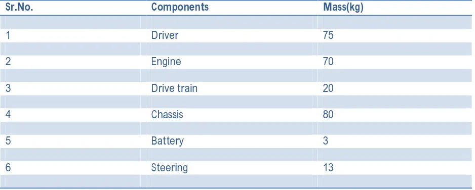
To estimate the various load which is acting on the vehicle are estimate according to the center of gravity of the vehicle. As the various load acting on the vehicle are distributed are shown in the below table.
Table-1: Mechanical Properties of Chassis
Sr.No. Components Mass(kg)
1 Driver 75
2 Engine 70
3 Drive train 20
4 Chassis 80
5 Battery 3
6 Steering 13
Available Online at www.ijpret.com
315
MATERIAL SELECTIONS
The material selection plays a dominant role in construction of the chassis, after the load estimation. Steel and aluminum are always the choice of the most of the team due to their properties such as the availability of the material tensile strength, cost and significant factor. After reviewing all the property AISI 1018 material was selected and the following test where conducted in ansys and the result are shown in this paper. The property of the selected material is shown in the below table.
Material Steel Grade: AISI018
Parameter Value Unit
Young's modulus 250 GPa
Poisons' Ratio .29
Density 7860 Kg/m3
Yields Strength 365 N/mm2
Carbon Content .18%
FINITE ELEMENT ANALYSIS
Front Impact Test
Available Online at www.ijpret.com
316
deacceleration of 69.44 m/sec2. Forces where applied at four points on the front crash members.
Figure-:10 Von Misses stresses during Front
Impact Test
Results showed the maximum Von misses stress value to be 1.8234*104 lbf/sq.in. Maximum deflection to be 0.058418 giving a factor of safety as 3.49.
Rear Impact Test
In Rear Impact Test the chassis is assumed to be crashing in a racing condition exactly perpendicular to velocity vector in the rear. Analysis was carried out by fixing the front of the chassis and forces of magnitude 3121.348lbf was applied with an impulse time of .8 sec and a deacceleration of 34.71 m/sec2.
Available Online at www.ijpret.com
317
Impact Test
Test Results showed the maximum Von misses stress value to be 1.7482*104 lbf/sq.in. Maximum deflection to be 0.21601 giving a factor of safety as 3.65.
Side Impact Test
In Side Impact Test the chassis is assumed to be crashing in a racing condition in the side impact member located along the cockpit. Analysis was carried out by fixing the front and rear of the chassis and forces of magnitude 4161.79lbf was applied with an impulse time of .6 sec and a deacceleration of 46.283 m/sec2.
Maximum principal stress of 5.4059*104 lbf/sq.in was observed and translational displacement of 0.33029 was observed.
Figure-12: Von Misses stresses during Side Impact Test
Torsional Test
Available Online at www.ijpret.com
318
Figure-13: Von Misses stresses during
Torsional Test
Results showed the maximum Von misses stress value to be 9136 and a maximum deflection to be 0.031087 was noted.
Roll over Test
In Rear Impact Test the chassis is assumed to be crashing in a racing condition exactly perpendicular to velocity vector in the rear. Analysis was carried out by fixing the front of the chassis and forces of magnitude 661.5864lbf was applied on the main roll hoop.
Available Online at www.ijpret.com
319
Table-2: Von Misses stresses during Roll over Test
Test Von misses Maximum
No. Stress(lbf/sq.in) Deflection
1 Front 1.8234*104 0.058418
Impact Test
2 Rear 1.7482*104 0.21601
Impact Test
3 Side 5.4059*104 0.33029
Impact Test
4 Torsional 9136 0.031087
Test
5 Rollover 6496 0.028295
Test
Rollover Test
Results showed the maximum Von misses stress value to be 1.8234*104. Maximum deflection to be 0.058418 giving a factor of safety as 3.49.
CONCLUSION
The Chassis that was design in accordance with the SAE Supra 2014 Rule book was considered to be safe and would be able to withstand the racing conditions.
Available Online at www.ijpret.com
320
is being absorbed which indicated that it has more that thrice the force capacity than the calculated value
Chassis was found to be safe significantly in static (bending) and dynamic (acceleration) modes with stress values noticeably less than the yield strength. Hence chassis was expected to perform well in motion also. Various Test can be carried out which can signify the controlled speed atmosphere and the behavior of the car on various road and harsh environments that above our level.
Test like the CFD, Chassis Balancing, Thermal Heating, Heat Treatment etc can be carried out on various manufacturing and stimulation software’s that can result in a more specific, sophisticated and detailed enquiry or analysis of the created Formulae-1 Module.
ACKNOWLEDGMENTS
The author would like to thank Asst. Prof. N. G. Jogi of J.D.I.E.T institute for supporting our project. I would like to thank all the authors who have experiments in this field.
REFERENCES
1. 2014 Formula SAE® Rules, SAE International, India
2. Fui, T.H., Rahman, R.A., 2007. Statics and Dynamics Structural Analysis of a 4.5 Ton Structural Analysis, Journal Mechanical, 24, 56-67.
3. Singh, R.P. and Kaur, T., 2009. Designing and fabrication of formula SAE vehicle (Chassis), National Conference on Innovative developments in engineering applications, Bhai Gurdas Institute of Engineering and Technology, Sangrur, Punjab, India, 265-271.
4. Ryan, A. 2008. Formula SAE Race Car Analysis: Simulation and Testing of the Engine as a structural member, Retrieved from http://www.fisita.com/students/congress/sc 08papers/f2008sc005.pdf on 06 June, 2010 03:40:37 GMT