Scalable Computing: Practice and Experience
Volume 15, Number 1, pp. 79–87. http://www.scpe.org
ISSN 1895-1767 c
2014 SCPE
IMAGE SCRAMBLING ON A ”MESH-OF-TORI” ARCHITECTURE∗
MARIA GANZHA†, MARCIN PAPRZYCKI‡, ANDSTANISLAV G. SEDUKHIN§
Abstract.
Recently, a novel method for image scrambling (and unscrambling) has been proposed. This method is based on a linear transformation involving the Kroneker-delta function. However, while quite interesting, the way it was introduced, leaves some open issues concerning its actual usability for information hiding. Therefore, in this paper, we extend the original proposal and show how it can be used to securely pass image-like information between the users.
87
1. Introduction. Recently we observe a constantly growing interest in processing multimedia content. Here, the multimedia content is understood broadly and encompasses “still images” of all types, as well as video streams. Since a video stream can be viewed (with all understandable caution) as a sequence of still images (video frames), let us focus our attention on images, while keeping in mind that data processing may involve their sequences.
Observe that, there are two main sources of large images. First, sensor arrays of various types. For instance, one of the largest of them is the 2D pixel matrix detector installed in the Large Hadron Collider in CERN [14], which has approximately 109 sensor cells. Similar number of sensors would be required in a CT scanner array
of size approximately 1m2, with about 50K pixels per 1cm2. Second, large data streams start to materialize in
“consumer electronics.” For instance, currently existing digital cameras capture images consisting of 22.3×10⁶
pixels (Cannon EOS 5D Mark II [3], as well as its successor Cannon EOS 6) or even 36.3×106 pixels (Nikon
D800 [4]). What is even more amazing, recently introduced Nokia phones (Nokia 808 PureView [5], and Nokia Lumia 1020 [6]) have cameras capturing 41×106pixels.
What has to be noted, from the point of view of computing (here, image processing), is that most of the existing sensor systems do not consider the natural arrangement of data. Specifically, the input image, which is square or rectangular, is “serialized” to be processed. Specifically, input data from multiple sensors is read out serially, pixel-by-pixel, and send to the CPU for processing1. Next, after processing is completed, results are
sent (serially) to a “display device,” where they are reassembled into a rectangular format. This means that the transfer of pixels destroys the 2D integrity of data (in computer memory, an image or a frame, existsnotin their natural layout). As a result, the need to transfer large amount of data, from “multiple data input streams” to the processor, may prohibit development of applications, which require (near) real-time response [10].
Observe that, for the (near) real-time image / video processing, as well as a 3D reconstruction, it could be advantageous to process them using a device that has multiple processing units arranged rectangularly, and that allows to load data directly from the sensors to these units (for immediate processing). This would be possible, for instance, when a focal-plane I/O, which maps the pixels of an image (or a video frame) directly into the stacked “array of processors,” was to be used. Here, the computational elements could store the sensor generated information (e.g. a single pixel, or a block of pixels of a specific size) directly in their registers (or their local memory). Such an architecture would have three potential advantages. First, cost could be reduced, because there would be no need for the memory buses or a complicated layout of the communication network. Second, speed could be improved as the integrity of the input data would not destroyed by the serial communication. Third, speed could be considerably improved by skipping the step of serialization of the rectangular image and, later, its reassembling in order to be displayed. As a result, data processing could start as soon as the data is available (i.e. in the registers / memory). Note that proposals for similar hardware architectures have been outlined, among others, in [9, 16, 26]. However, such approaches have not been tried in real-life. Furthermore, previously proposed focal-plane array processors were envisioned with a mesh-based interconnect between the
∗Work of Marcin Paprzycki was completed while visiting the University of Aizu.
†Systems Research Institute Polish Academy of Sciences, Warsaw, Poland, email: maria.ganzha@ibspan.waw.pl ‡Systems Research Institute Polish Academy of Sciences, Warsaw, Poland, email: marcin.paprzycki@ibspan.waw.pl §University of Aizu, Aizu Wakamatsu, Japan, email: sedukhin@u-aizu.ac.jp
1
Here, the term CPU is used broadly and encompasses standard processors, GPU’s, Digital Signal Processing units, etc.
2. Mesh-of-tori interconnection topology. This discussion leads us to the following question. As-suming that the focal plane I/O like approach is used to provide an effective data transfer to a rectangularly arranged group of processing units, what network topology should be used to connect them. Here, the experi-ences from development of parallel supercomputers could be useful. Historically, a number of topologies have been proposed, and the more interesting of them were: (1) hypercube – scaled up to 64000+ processor in the Connection Machine CM-1, (2) mesh – scaled up to 4000 processors in the Intel Paragon, (3) processor array – scaled up to 16000+ processor in the MassPar computer, (4) rings of rings – scaled up to 1000+ processors in the Kendall Square KSR-1 machines, and (5) torus – scaled up to 2048 units in the Cray T3D.
However, all of these topologies suffered from the fact that at least some of the elements were reachable with a different latency than the others. This means, that algorithms implemented on such machines would have to be asynchronous, which works well, for instance, for ising-model algorithms similar to these discussed in [8], but is not acceptable for most computational problems, that require synchronous data access. Therefore, an extra latency had to be introduced, for the processing units to wait for the information to be propagated across the system. Obviously, this effect became more visible with the increase of the number of processing units. At the same time, miniaturization counteracted this process only to some extent. Interestingly, supercomputers with some of the most efficient network connectivity, the IBM Blue Gene machines, combine the toroidal network with an extra networking provided for operations involving global communication (primarily, reduction and broadcast). To overcome this problem, recently, a new (mesh-of-tori; MoTor) parallel computer architecture (and topology) has been proposed. Let us now summarize this proposal. What follows is based on [20] and this source should be consulted for further information.
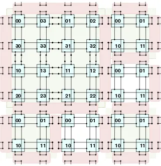
The fundamental (indivisible) unit of theMoTor system is aµ-Cell. Theµ-Cell consists four computational units connected into a 2×2 doubly-folded torus (see, Figure 2.1). Logically, an individualµ-Cell is surrounded by so-called membranes that allow it to be combined into larger elements through the process of cell-fusion. Obviously, collections ofµ-Cells can be split into smaller structures through cell division. For instance, in Figure 2.1, we see a total of 9µ-Cells logically fused into a single macro-µ-Cell consisting of 4µ-Cells (combined into a 4×4 doubly folded torus), and 5 individual (separate)µ-Cells. Furthermore, in Figure 2.2 we observe all nine
µ-Cells combined into a single system (a 6×6 doubly folded torus; with a total of 36 processing units). Observe that, when the 2×2 (or 3×3)µ-Cells are logically fused (or divided), the newly formed structure remains a doubly folded torus. In this way, it can be postulated that the single µ-Cell represents a “holographic image” of the whole system.
Let us note that the proposedMoTor topology has similar restriction as the array processors from the early 1990’s. Specifically, theMoTor system must be square. While this was considered an important negative factor in the past, this is no longer the case. When the first array processors were built and used, arithmetical opera-tions and computer memory were “expensive.” Therefore, it was necessary to avoid performing “unnecessary” operations (and maximally reduce the memory usage). Today (December 2013), when GFlops costs about 16 cents (see, [25]) and its price is systematically dropping; and when laptops come with 8 Gbytes of RAM (while some cell phones include as much as 64 Gbytes of flash memory on a card), it is the data movement / access / copying that is “expensive” (see, also [13]). Therefore, when images (matrices) are rectangular (rather than square), it is reasonable to assume that one could just pad them up, and treat them as square. Obviously, since theµ-Cell is a single indivisible element of theM oT or system, if the matrix is of sizeN×N thenN has to be even (or padded to be such).
03 00
33 30
13 10
23 20
01 00
11 10
02 01
32 31
12 11
22 21
01 00
11 10
01 00
11 10
01 00
11 10
01 00
11 10
Fig. 2.1.9µ-Cells fused into a single2×2“system,” and 5 separateµ-Cells
in Figure 2.1 shows that (4) thegfma unit should include four interconnects that allow assembly of the MoTor
system. Let us name such computational unit the extended generalized fma: egfma. Furthermore, let us keep in mind that the MoTor architecture is build fromindivisible µ-Cells, each consisting of four, interconnected into a doubly folded torusegfma units.
Let us now observe that there are two sources of inspiration for the M oT or system: (i) processing data from, broadly understood, sensor arrays (e.g. images), and (ii) matrix computations. Furthermore, we have stated that the egfma should contain data registers to store (a) the needed scalar elements originating from various semirings, (b) data that the fma is to operate on and, as stipulated in [11], (c) elements constituting special matrices needed for matrix operations / transformations. Here, we have to take into account that each
egfma should have a “local memory” to allow it to process “blocks of data.” This idea is based on the following insights. First, if we define a pixel as “the smallest single component of a digital image” (see, [7]), then the data related to a single RGBX-pixel is very likely to be not larger than a single 32 bit number. Second, in early 2013 the (Tianhe-2) has 23,040,000fmaunits2 (see, [2]). This means that, if there was a one-to-one correspondence
between the number ofegfma units and the number of “pixels streams,” then the system could process stream of data from 23 Megapixel input devices (or could process a matrix / image of sizeN ≃4800). This is clearly not enough. Finally, let us note that to keep an fma / gefma unit operating at 100% it is necessary to form a pipeline that is (minimally) 4-6 elements deep. Therefore, from here on, we will assume (and in this follow [19])
2
05 00
55 50
15 10
45 40
25 20
35 30
04 01
54 51
14 11
44 41
24 21
34 31
03 02
53 52
13 12
43 42
23 22
33 32
Fig. 2.2.9µ-Cells fused into a single6×6EG FMA system
that each computational unit in theMoTor system has local memory and thus be capable of processing blocks of data. For instance, a natural way of augmenting theegfma to achieve this goal would be to use 3D stacked memory [15].
Let us now consider the development of the MoTor-based system. In the initial works, e.g. in [20], links between cells have been conceptualized as purely abstract links (µ-Cells were surrounded by logical membranes that could be fused or divided as needed, to match the size of the problem). Obviously, in an actual system, the abstract links and membranes could be realized logically, while the whole system would have to be hard-wired to form an actualMoTor system (of a specific size). Therefore to build a large system withM2µ-Cells (recall the
assumption that the MoTor system will have the form of a square array), it can be expected that such system will consist of silicon etched groups of µ-Cells residing on separate chips (µ-processors), combined into the
MoTor system of a given size (similarly to multicore / multi-FMA processors combined into supercomputers). As what concerns cell fusion and division, it will be possible to assemble sub-system(s) of a needed size, by logically splitting and/or fusing an appropriate number of cells within theM oT orsystem. However, it should be stressed that while thetheoretical communication latency across theMoTor system is uniform, this is not likely going to be the case when the system will be assembled fromµ-processors constituting physical macro-µ-Cells. In this case it may be possible that the communication within the µ-processor (physical macro-µ-Cell) will be relatively faster than between theµ-processors. Therefore, the most naturalµ-Cell split should involve complete
hardware configuration.
3. Fundamental operation. To proceed, let us note that, in what follows, we use the generalized matrix multiply-and-update operation (MMU) in the form elaborated in [23, 12, 11]:
C←MMU[⊗,⊕](A,B,C) :C←C⊕AN/T⊗BN/T.
Here,A,B andC are square matrices of (even) sizeN; while the ⊗,⊕operations originate from a matrix semiring; and N/Tspecify if a given matrix is to be treated as being in a standard (N) or in a transposed (T) form, respectively.
3.1. Reordering for the mesh-of-tori processing. Before discussing image processing, which is the main contribution of this paper, we have to consider the data input (e.g. from the sensor array, a medical scanner, or a cell phone photo camera) into the MoTor system. As shown in [20] (and followed in [11]), any input that is in the canonical (standard image / square matrix) arrangement, is not organized in a way that is needed for the matrix processing in a (doubly folded) torus. However, as shown in [19], the needed format can be obtained by an appropriate linear transform, through two matrix-matrix multiplications. Specifically, matrix product in the form M ←R×A×RT, whereA is the original / input (N×N) matrix that is to be
transformed,M is the matrix in the format necessary for further processing on theMoTor system, andRis the format rearranging matrix (for the details of the structure of the R matrix, consult [19]). Taking into account the implementation of the generalized MMU operation (see, equation 3), the needed transformation has the form:
M =R×A×RT.
Note that, according to [20, 19], on theM oT orsystem: (a) operationZ=R×Ais performed in place and requires N time steps, (b) operationM =Z ×RT is performed in place, and also requires N time steps and
is implemented as a parallel matrix multiplication with a different data movement pattern than the standard multiplication. In other words, the matrix arrangement within the system remains unchanged for the transposed matrix operations, and the well-known problems related to row vs. column matrix storage (see, for instance, [17]) do not materialize (for more details, see [24]).
Observe that, when instantiating the M oT or system, it is assumed that an appropriate matrix R will be preloaded into the macro-µ-Cell, upon its creation (see, [11] for more details). Specifically, in addition to the operand registers dedicated to special elements (¯0,¯1) originating from selected semirings, appropriate elements of a transformation matrix, needed to perform operations summarized in [11] will be preloaded in separate operand registers. These operations include the transformation from the canonical to the “MoTor format” and back. Therefore, matrix R(of an appropriate size) will be preloaded into theM oT oRsystem.
4. Image scrambling and unscrambling. Taking into account the background material presented thus far, let us focus on the main contribution of this paper. An interesting application of the matrix multiplication has been proposed in [18]. There, a linear transform, based on the Kronecker-delta function, was introduced. This transformation was then used to create a scrambling matrix C that could be used to scramble and un-scramble images (via matrix-matrix multiplication). Since matrix denoted as “C” is very often used in different contexts (e.g. see, the above equation 3), for the purpose of this paper, let us re-name it as SCRAM. The complete description of the linear transform, as well as the specific structure of the SCRAM matrix can be found in [18]. Let us recall that, while the discussion below considers “single element per gefma” model, the real assumption is that a “data block pergefma” format is used (for more details, see [18, 19]). Therefore, all claims should be seen as actually concerning ablocked data format. Finally, we assume that image / matrixA
is of size N×N (withN even).
Similarly to the processing needed to transform the matrix / image from the canonical to the MoTor
In [18], two ways to apply this approach to scramble images have been proposed. First, scrambling was to be applied 1≤J ≤N times to the whole image (matrix). The second approach was a “progressive” one. Here, one had to pick a key (parameter) 1 ≤KP ≤ N. Next, scrambling was applied to the left top corner of the
image, of size KP×KP, 2KP×2KP, and proceeded until the whole matrix was scrambled (in the case when
N was not divisible byKP then the complete matrix / image was scrambled in the last step).
In both cases, the scrambling operation could be realized by aScramble(A, nb) function. This function was to perform the tripe-matrix product involving the left top corner of sizenb×nb, where 1≤nb≤N. In the first approach, scrambling was achieved by calling theScramble(A, N) functionJtimes. Observe that, on theMoTor
system, each scrambling step would be performed in place, and would take 2N time steps. Therefore, the total cost of scrambling would be 2N ≤2N J≤2N2time steps. Here, to unscramble the image without knowledge of
the key K, would require knowledge of the matrixSCRAM, and applying the unscrambling operationJ times (using function ScrambleInv(A, N)) until the original image was to be revealed (to the human observer).
In the second case, theScramble(A, nb) function would be calledN/KP times (and possibly one more time
ifN was not divisible byKP). On theMoTor system, each scrambling step would cost 2KP time steps (plus
the cost of cell fusion, and of re-instantiating the SCRAM matrix (for the next image / matrix size); however, these costs would be negligible in comparison with the cost of matrix multiplication). Therefore, the total cost would be between 2N (forKP =N) and 4N−2 for (forKP = 1) time steps. Here, recovering the original
image would require knowledge of the matrix SCRAM, and searching space of all possible values of KP, by
applying the unscrambling function ScrambleInv(A, nb).
Let us stress that the material presented in [18], while conceptually originating from the same roots (dense matrix multiplication), was not directly related to the MoTor architecture. Furthermore, it did not consider practicalities of use of the proposed transformation for secure image (multimedia) transfer / communication. Earlier, we have already made some comments about possible implementation of the scrambling (and unscram-bling) procedures on the MoTor system, conceptualized as above (and approached as in [11]). Let us continue this line of reasoning.
First, let us make an obvious observation. The goal of image scrambling is to be able to hide the in-formation (make the image unrecognizable to unauthorized persons), pass it to the authorized recipient, and reveal it by unscrambling. In this context, let us consider in some detail the implementation of the proposed image scrambling on a MoTor system. Here, the first approach involves initialization of theSCRAM matrix (similarly to the R matrix mentioned above, and to other transformation matrices summarized in [11]). Note that, only a single SCRAM matrix is going to be needed, as the scrambling procedure consists of applica-tion of the Scramble(A, N) function J times to the whole image (matrix). As stated above, this approach is not safe at all. As soon as the potential attacker knows the SCRAM matrix, (s)he can repeatedly apply the
ScrambleInv(A, N) function and afterJ steps the original image will be revealed. Furthermore, the computa-tional cost of unscrambling will be the same as that of scrambling (assuming that the attacker also has aMoTor
system at her/his disposal).
The situation is different in the second approach. Here, even the knowledge of theSCRAMmatrix, and the possession of the MoTor system, do not help the potential attacker sufficiently. Without the knowledge of the
KP parameter, the search space to uncover the information is much larger (though, obviously, the unscrambling
is not impossible). However, this approach would be somewhat difficult to efficiently implement on a MoTor
system (as described above, and in [11]). Observe that the recursive approach would require cell fusion. For instance, ifKP = 64 then the first scrambling would be performed on a block of size 64×64 (on a macro-µ-Cell
consisting of 32×32µ-Cells). Next, cell fusion would have to be applied (to create a macro-µ-Cell consisting of 64×64µ-Cells, and matrixSCRAM would have to be re-initialized, to apply scrambling to a block of size 128×128). In other words, let us assume that image of size 1024×1024 is to be scrambled, with the key
KP = 16. This means that the macro-µ-Cells of size 8, 16, 32, 64, 128, 256 and 512 would have to be used, and
values ofKP). Here, it should be stressed that, while use of odd values ofKP is possible, this does not match the
concept of the MoTor system, where theµ-Cell is the fundamental computational unit. Furthermore, this also means that there is no natural way of utilizing the cell fusion and splitting that could allow dynamic creation of theMoToRsystems that match the size of the scrambled block. Finally, note that padding, proposed above for the full-matrix operations, is not an option in an “internal step” of image scrambling, as the scrambling operation has to be performed on a block of data within an image (matrix).
Summarizing, while very interesting conceptually, ideas for image scrambling presented in [18] are not best suited for theMoTor architecture. Therefore, we propose a slightly different approach to image scrambling (and unscrambling), seen as a mechanism for information hiding (and safe transmission) on aMoTorarchitecture. Let us assume that two users would like to communicate multimedia content using the scrambling / unscrambling method discussed above. Observe that, for any matrix A, as long as the SCRAM matrix is known, the
ScrambleInv(A, nb) reverses the effect of application of the Scramble(A, nb) function. This being the case, it is easy to see that all that is needed is that the sender applies the Scramble(A, nb) function a specific number of times (e.g. L times) for the selected values of nb. Next, it communicates to the receiver a tuple (nb1, nb2, . . . , nbL) that defines what were the values ofnbi used in each of the scrambling steps, and what was
their order. Here, we assume that the SCRAM matrix is known to both the sender and the receiver. Next, the receiver applies theScrambleInv(A, nb) function in an appropriate order (based on the known sequence of
nbivalues) to recover the original image. A small “restriction” on this approach is such that at least one of the
scrambling operations should involve the whole matrix A (as application of only blocked scrambling, without scrambling the whole image, leaves an unscrambled image strip; see [18, 19]). However, this approach makes it very difficult to unscramble the original image even if the attacker knows the form of the matrixSCRAM. The problem is in the fact that the sequence (nb1, nb2, . . . , nbL) can be completely “random,” while being known
only to the sender and the receiver.
The interesting part of this approach is in the fact that the number different blocks used in scrambling does not have to be large (as they can be repeated in the scrambling sequence) and that they can be defined in such a way to match the structure of the MoTor system. Here, let us recall that the size of the macro-µ-Cell can be dynamically adjusted through cell division and fusion. However, the image (matrix) Ais stored across the whole MoTor system and this fact is not going to change. Let us now assume that the following scrambling sequence is to be applied nb= 1024,256,512,1024 to a matrix (image) of size 1024×1024. Here, it is possible (assuming that this is known in advance) to instantiate three SCRAM matrices in theMoTor system. Each element of these SCRAM matrices would be stored in a separate register. Now, the first scrambling would involve triple-matrix multiplication performed on the whole system. Next, the cell division would be applied to create a subsystem of size 256×256 (macro-µ-Cell consisting of 128×128µ-Cells). Here, let us note that this subsystem would have preloaded SCRAM matrix of the correct size. In the following step, cell fusion would be used to create a subsystem of size 512×512 (macro-µ-Cell consisting of 256×256µ-Cells); where an appropriateSCRAM matrix would be already preloaded. After the scrambling operation, cell fusion would be applied, again, to restore the original system, where the initial SCRAM matrix would still be available. Another triple-matrix multiplication would end the process. The unscrambling will proceed in exactly the opposite order, dynamically splitting and fusing the meta-µ-Cells and using the preloadedSCRAM matrices.
i n t e r f a c e M a t r i x i n t e r f a c e {
p u b l i c M a t r i x 0 ( i n t n ) {/∗g e n e r a l i z e d z e r o m a t r i x∗/} p u b l i c M a t r i x I ( i n t n ) {/∗g e n e r a l i z e d i d e n t i t y m a t r i x∗/} p u b l i c M a t r i x o p e r a t o r + /∗g e n e r a l i z e d A+B∗/
p u b l i c M a t r i x o p e r a t o r ∗ /∗g e n e r a l i z e d A∗B∗/ p u b l i c M a t r i x C a n o n i c a l t o M o t o r ( M a t r i x A ) ; /∗r e o r d e r i n g f o r t h e mesh−o f−t o r i p r o c e s s i n g∗/
p u b l i c M a t r i x M o t o r t o C a n o n i c a l ( M a t r i x A) ; /∗i n v e r s e o f t h e r e o r d e r i n g f o r t h e mesh−o f−t o r i p r o c e s s i n g∗/
p u b l i c M a t r i x S c r a m b l e ( M a t r i x A, i n t nb ) ; /∗M a t r i x ( Image ) S c r a m b l i n g∗/
p u b l i c M a t r i x S c r a m b l e I n v ( M a t r i x A, i n t nb ) ; /∗M a t r i x ( Image ) U n sc r a m b l i n g∗/
}
This interface is to be used with the following classMatrix that summarizes the proposals outlined above.
c l a s s Matrix i n h e r i t s c a l a r S e m i r i n g
implement M a t r i x i n t e r f a c e {
T : ty p e o f e l e m e n t ; /∗double , s i n g l e , . . .∗/
p r i v a t e Matrix SCRAM ( i n t n ) /∗s c r a m b l i n g m a tr i x p r i v a t e Matrix R ( i n t n ) ; /∗m a tr i x f o r MoTor
t r a n s f o r m a t i o n∗/
p r i v a t e Matrix ONES ( i n t n ) /∗ m a tr i x o f o n e s∗/ p r i v a t e Matrix PERMUT( i n t i , j , n )/∗i d e n t i t y m a tr i x
with i n t e r c h a n g e d columns i and j∗/ // a n t i−d i a g o n a l m a tr i x o f o n e s
p r i v a t e Matrix SWAP ( i n t n ) // Methods
p u b l i c Matrix 0 ( i n t n ) {/∗0 m a tr i x∗/}
p u b l i c Matrix I ( i n t n ) {/∗i d e n t i t y m a tr i x∗/}
p u b l i c Matrix t r a n s p o s e ( Matrix A){
/∗MMU−based t r a n s p o s i t i o n o f A∗/}
p u b l i c Matrix o p e r a t o r + ( Matrix A, B)
{r e t u r n MMU(A, I ( n ) ,B , a , b )}
p u b l i c Matrix o p e r a t o r ∗ (A, B : Matrix )
{r e t u r n MMU(A, B, m a tr i x 0 , a , b )}
. . .
/∗image s c r a m b l i n g∗/
p u b l i c Matrix Scramble ( Matrix A, i n t nb ){
r e t u r n SCRAM ∗ A ∗ SCRAMˆT};
p u b l i c Matrix S c r a m b l e In v ( Matrix A, i n t nb ){
r e t u r n SCRAMˆT ∗ A ∗ SCRAM}; . . .
p r i v a t e MMU(A, B ,C : Matrix ( n ) ){
r e t u r n ” vendor / i m p l e m e n te r s p e c i f i c r e a l i z a t i o n o f MMU = C + A∗B where + / ∗ a r e from c l a s s s c a l a r S e m i r i n g ”}
. . .
}
Obviously, this class and the interface would allow writing codes in the suggested manner. Here, the matrix operations (image scrambling and unscrambling) would be performed by calling simple functions, and hiding all implementation details (including the existence of the matrixSCRAM) from the user.
we have illustrated how the proposed approach fits into the object oriented realization of matrix operations proposed in [11]. In the future we plan to implement the proposed approach on the virtual MoTor system and study its efficiency.
Acknowledgment. Work of Marcin Paprzycki was completed while visiting the University of Aizu.
REFERENCES
[1] Kalray multi-core processors. http://www.kalray.eu/. [2] Top500 list. http://www.top500.org.
[3] Canon EOS 5D.http://www.usa.canon.com/cusa/consumer/products/cameras/slr_cameras/eos_5d_mark_iii, 2013. [4] Nikon D800.http://www.nikonusa.com/en/Nikon-Products/Product/Digital-SLR-Cameras/25480/D800.html, 2013. [5] Nokia 808 Pureview.http://reviews.cnet.com/smartphones/nokia-808-pureview-unlocked/4505-6452_7-35151907.html,
2013.
[6] Nokia Lumia 1020.http://www.nokia.com/global/products/phone/lumia1020/, 2013. [7] Wikipedia pixel. http://en.wikipedia.org/wiki/Pixel, March 2013.
[8] P. Altevogt and A. Linke,Parallelization of the two-dimensional ising model on a cluster of ibm risc system/6000 work-stations, Parallel Computing, 19 (1993), pp. 1041–1052.
[9] S. Chai and D. Wills,Systolic opportunities for multidimensional data streams, Parallel and Distributed Systems, IEEE Transactions on, 13 (2002), pp. 388–398.
[10] D. Fey and D. Schmidt,Marching-pixels: a new organic computing paradigm for smart sensor processor arrays, in CF ’05: Proceedings of the 2nd conference on Computing frontiers, New York, NY, USA, 2005, ACM, pp. 1–9. doi:http: //doi.acm.org/10.1145/1062261.1062264.
[11] M. Ganzha, M. Paprzycki, and S. Sedukhin,Library for matrix multiplication-based data manipulation on a “mesh-of-tori” architecture, in Proceedings of the 2013 Federated Conference on Computer Science and Information Systems, M. Ganzha, L. Maciaszek, and M. Paprzycki, eds., IEEE, 2013, pp. pages 455–462.
[12] M. Ganzha, S. Sedukhin, and M. Paprzycki,Object oriented model of generalized matrix multiplication, in FedCSIS, IEEE, 2011, pp. 439–442.
[13] J. L. Gustafson,Algorithm leadership, HPCwire, Tabor Communications (April 06, 2007).
[14] E. H. M. Heijne,Gigasensors for an attoscope: Catching quanta in CMOS, IEEE Solid State Circuits Newsletter, 13 (2008), pp. 28–34.
[15] P. Jacob, A. Zia, O. Erdogan, P. M. Belemjian, J.-W. Kim, M. Chu, R. P. Kraft, J. F. McDonald, and K. Bernstein,
3D memory stacking; mitigating memory wall effects in high-clock-rate and multicore CMOS 3-D processor memory stacks, Proceedings of the IEEE, 97 (2009).
[16] S. Kyo, S. Okazaki, and T. Arai,An integrated memory array processor architecture for embedded image recognition systems, in Computer Architecture, 2005. ISCA ’05. Proceedings. 32nd International Symposium on, June 2005, pp. 134– 145.
[17] M. Paprzycki,Parallel Gaussian elimination algorithms on a Cray Y-MP, Informatica, 19 (1995), pp. 235–240.
[18] A. Ravankar and S. Sedukhin,Image scrambling based on a new linear transform, in Multimedia Technology (ICMT), 2011 International Conference on, 2011, pp. 3105–3108.
[19] A. A. Ravankar,A new “mesh-of-tori” interconnection network and matrix based algorithms, master’s thesis, University of Aizu, September 2011.
[20] A. A. Ravankar and S. G. Sedukhin,Mesh-of-tori: A novel interconnection network for frontal plane cellular processors, 2013 International Conference on Computing, Networking and Communications (ICNC), (2010), pp. 281–284.
[21] ,An O(n) time-complexity matrix transpose on torus array processor, in ICNC, 2011, pp. 242–247.
[22] S. G. Sedukhin and T. Miyazaki,Rapid*closure: Algebraic extensions of a scalar multiply-add operation, in CATA, 2010, pp. 19–24.
[23] S. G. Sedukhin and M. Paprzycki,Generalizing matrix multiplication for efficient computations on modern computers, in Parallel Processing and Applied Mathematics, R. Wyrzykowski, J. Dongarra, K. Karczewski, and J. Wa´sniewski, eds., vol. 7203 of Lecture Notes in Computer Science, Springer Berlin Heidelberg, 2012, pp. 225–234.
[24] S. G. Sedukhin, A. S. Zekri, and T. Myiazaki,Orbital algorithms and unified array processor for computing 2D sepa-rable transforms, in Parallel Processing Workshops, International Conference on, Los Alamitos, CA, USA, 2010, IEEE Computer Society, pp. 127–134.
[25] Wikipedia,Flops. http://en.wikipedia.org/wiki/FLOPS. [26] A. Zar´´ andy,Focal-Plane Sensor-Processor Chips, Springer, 2011.
Edited by: Dana Petcu
Received: Dec 1, 2013