Available Online At www.ijpret.com
INTERNATIONAL JOURNAL OF PURE AND
APPLIED RESEARCH IN ENGINEERING AND
TECHNOLOGY
A PATH FOR HORIZING YOUR INNOVATIVE WORK
STUDY OF ISSUES IN AUTOMATIC VEHICLE OVERTAKING SYSTEM FOR ACCIDENT
AVOIDANCE
POONAM C. GHADGE1, POOJA S. BANDAL1, HARSHADA P. HOLE1, Prof. S. M. SANGVE2.
1. Student of DCOER, Pune.
2. Department of Computer Engineering, DCOER, Pune.
Accepted Date:
14/10/2012
Publish Date:
01/11/2012
Keywords
Negligence
Dozing off
Prolongs driving
Corresponding Author Mr. Poonam C. Ghadge
Student of DCOER, Pune.
Abstract
With the advent of industrialisation and increasing luxurious
lifestyle, transportation has become the major part of our
lives. Today large numbers of vehicles run during day and
night time. Nowadays the number of accidents is increasing
due to negligence of the driver. Negligence such as dozing
off, attending phone calls, lack of awareness, exhaustion
due to prolong driving, etc.
This project covers overtaking of the vehicles without
manual efforts. The sensors will be present on the vehicle
which will be detecting the distance between the
neighbouring vehicles and itself. When this distance
reduces, the sensors will sense them and the overtaking
Available Online At www.ijpret.com INTRODUCTION
The development of advanced driver
assistance systems (ADAS) to aid in
driving-related tasks has a key role to play in the
automotive field.
Assistance systems – to prevent accidents
or to make driving safer – which alert the
driver of imminent risks through visual or
audible signals have been included in
commercial cars in recent years. Although
these techniques are necessary and provide
a warning to the driver, their dependence
on human reaction time for a decision to be
made remains a problem.
The first system introduced in commercial
vehicles with the potential to influence
traffic safety was adaptive cruise control
(ACC) .This was an extension of cruise
control (CC) – CC allows the driver to set a
driving speed – in which the vehicle is
capable of following a leading car on
highways by automatic action on the
throttle and brake pedals, i.e., longitudinal
control. Lateral or steering control,
however, remains one of the toughest
challenges in the development of
commercial ADAS. The currently most
advanced system is lane keeping assistance
(LKA) which provides limited additional
steering torque to aid the driver in
maintaining the vehicle within the lane if a
potential lane departure is detected. In
previous work, a lane-change controller was
developed in the AUTOPIA program,
determining experimentally the relationship
between the speed and the lane-change
distance using vehicle-to-vehicle (V2V)
communication to perform the maneuver.
This system was based on a prior
knowledge of the state of the road.
However, the development of ADAS in
mass-produced cars allows one to assume
that autonomous or semi-autonomous
vehicles will be driving on our roads in the
medium to long term. Consequently, it is
obligatory to have a system capable of
permitting the coexistence of these.
Tri-state address pins providing a maximum
of 531,441 (or 312 kinds of vehicle with
today’s human driven vehicles on the roads.
Given this premise, all the sensorial
information will have to be on board the
autonomous vehicle, and the path-tracking
actually generated will have to depend on
Available Online At www.ijpret.com a system whose behavior is as close to that
of the human driver as we can make it. To
this end, different trajectories will be
generated depending on the leading
vehicle’s characteristics as obtained from
vision-based information.
Figure 1 Car Safety System
II. Related Work:
If you have ever driven a car with an
automatic transmission, then you know that
there are two big differences between an
automatic transmission and a manual
transmission:
* There is no clutch pedal in an automatic
transmission car.
* There is no gear shift in an automatic
transmission car. Once you put the
transmission into drive, everything else is
automatic.
Both the automatic transmission (plus its
torque converter) and a manual
transmission (with its clutch) accomplish
exactly the same thing, but they do it in
totally different ways. It turns out that the
way an automatic transmission does it is
absolutely amazing!
A. Encoder
What is Encoder?
An encoder is a device, circuit, transducer,
software program, algorithm or person
that converts information from one format
or code to another, for the purposes of
standardization, speed, secrecy, security, or
saving space by shrinking size.
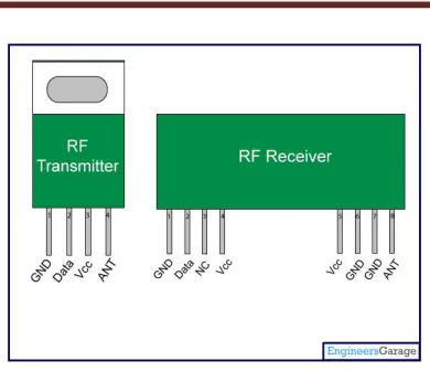
B. RF Module
The RF module, as the name suggests,
operates at Radio Frequency. The
corresponding frequency range varies
between 30 kHz & 300 GHz. In this RF
system, the digital data is represented as
variations in the amplitude of carrier wave.
This kind of modulation is known as
Available Online At www.ijpret.com Figure 2 RF Module
Transmission through RF is better than IR
(infrared) because of many reasons. Firstly,
signals through RF can travel through larger
distances making it suitable for long range
applications. Also, while IR mostly operates
in line-of-sight mode, RF signals can travel
even when there is an obstruction between
transmitter & receiver. Next, RF
transmission is more strong and reliable
than IR transmission. RF communication
uses a specific frequency unlike IR signals
which are affected by other IR emitting
sources.
This RF module comprises of an RF
Transmitter and an RF Receiver. The
transmitter/receiver (Tx/Rx) pair operates
at a frequency of 434 MHz An RF
transmitter receives serial data and
transmits it wirelessly through RF through
its antenna connected at pin4. The
transmission occurs at the rate of 1Kbps -
10Kbps.The transmitted data is received by
an RF receiver operating at the same
frequency as that of the transmitter.
C. Decoder:
Definition
A decoder is a device which does the
reverse operation of an encoder, undoing
the encoding so that the original
information can be retrieved. The same
method used to encode is usually just
reversed in order to decode. It is a
combinational circuit that converts binary
information from n input lines to a
maximum of 2n unique output lines.
PT2272 is a remote control decoder paired
with PT2262 utilizing CMOS Technology. It
has 12 bits of) address codes; thereby,
drastically reducing any code collision and
unauthorized code scanning possibilities.
PT2272 is available in several options to suit
every application need: variable number of
data output pins, latch or momentary
Available Online At www.ijpret.com D. IR Sensors
It consists of ir transmitters and receivers.
In this project we are using three ir sensors.
Uses of sensors:
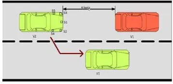
Use of front sensor
When the front sensor detects that vehicle
is below the safe limit then it will check for
sufficient space and will move the vehicle
right up to a specific distance and specific
angles and will overtake the car.
Figure 3 Front Sensor Working
Use of right sensor
If another vehicle is in right then right
sensor gets activated. Here, if this condition
is satisfied then vehicle will shift itself left at
a particular distance and at a given angle it
will move and will overtake the front
vehicle.
Figure 4 Right Sensor Working
Use of left sensor
If another vehicle is in left then left sensor
gets activated.Here, if this condition is
satisfied then vehicle will shift itself right at
a particular distance and at a given angle it
will move and will overtake the front
vehicle.
Figure 5 Left Sensor Working
III. DESCRIPTION OF MODULE
Available Online At www.ijpret.com Microcontroller
Keypad will have 3 buttons – left, right,
front.
Microcontroller GPIO pins configured for
receiving input will sense which key is
pressed. Generate an event and
Interrupt system signals microcontroller to
call Interrupt Service Routine.
It in turn generates a digital signal for
encoder.
Encoder
Encoder converts incoming signal digits to
pulses
e.g. –
If 0 then length of pulse be 38 PIC
instructions.
If 1 then length of pulse be 102 PIC
instructions.
RF transmitter
Transmitter transmits signals from keypad
to receiver located in vehicle. Its range is
now predicted to be 100 meters
B. Vehicle:
RF Receiver
RF receiver is located in vehicle. Receiver
receives signals from keypad and gives it to
decoder.
Decoder
Decoder is situated between RF receiver
and microcontroller of vehicle. Decoder
converts incoming pulses to digits.
Microcontroller
Microcontroller GPIO pins configured for
receiving input will receive digits from
decoder.
Generate an Input event and Interrupt
system signals microcontroller to call
Interrupt Service Routine.
It in turn generates a signal for motor.
Motor is responsible to move vehicle.
Current Amplifier
To increase strength of current so that it
can drive motor.
Relay Circuit
There is a coil inside. When current flows
through the coil a magnetic field causes the
internal paddle to move positions. This
paddle usually carries large currents or
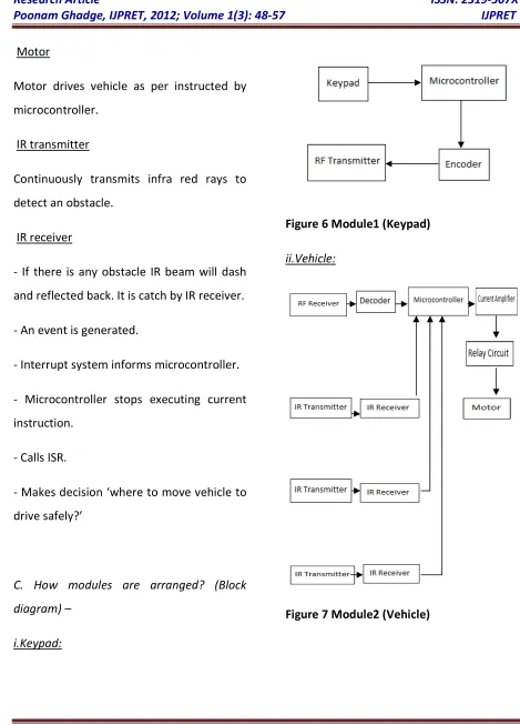
Available Online At www.ijpret.com Motor
Motor drives vehicle as per instructed by
microcontroller.
IR transmitter
Continuously transmits infra red rays to
detect an obstacle.
IR receiver
- If there is any obstacle IR beam will dash
and reflected back. It is catch by IR receiver.
- An event is generated.
- Interrupt system informs microcontroller.
- Microcontroller stops executing current
instruction.
- Calls ISR.
- Makes decision ‘where to move vehicle to
drive safely?’
C. How modules are arranged? (Block
diagram) –
i.Keypad:
Figure 6 Module1 (Keypad)
ii.Vehicle:
Available Online At www.ijpret.com FUZZY LOGIC BASED INTEGRATED CONTROL
SYSTEM
Recently, various electronic control
techniques and control systems, such as
anti-lock braking system, traction control
system, and so on are being developed
greatly and applied widely to improve the
ride comfort, safety and operation stability
in vehicle. Many theories and design
methods for antilock braking systems have
been proposed several literatures for
decades. Researchers have considered a lot
of control strategies and methods of
anti-lock braking systems, which have been
demonstrated effective for ABS system.
Georg.F.Mauer proposed Fuzzy technique
for ABS in 1995 and David E Nelson has
implemented fuzzy logic based
ABS for electric vehicle. Now computers are
increasingly in driving-related tasks in some
commercial vehicles. As evident from
literature, collision warning and avoidance
systems
are currently of prime interest in present
automotive research and development.
Fuzzy techniques are proposed for CAS by
Jose E. Naranjo, Carlos Gonzalez and Chan
yet Wong. However, none of these papers
investigated regarding simultaneous control
of ABS and CAS. In this paper we make an
Attempt to control both ABS and CAS
together and control logic is fuzzy logic
based. Moreover, this is implemented in
HCS12 microcontroller using CAN protocol
and important results are brought out.
When there are more electrical control
devices in the modern cars, such as power
train management system, antilock braking
system (ABS), and acceleration skid control
(ASC) system, etc, the functionality and
wiring of these electric control units are
getting more complicated. Therefore, it is of
great concern to upgrade the traditional
wire harness to a
Smart car network. In 198Os, a Germany car
component provider Robert Bosch Co.
introduced an in-car network; the controller
area network (CAN) bus, to replace the
complex and expensive traditional in-car
Available Online At www.ijpret.com CONCLUSION
Calibrating the alignment of automotive
distance radar modules during installation
and subsequent service in automotive
workshops by means of directly analyzing
the direction of the radar beam is a
challenging task putting high requirements
on accuracy, robustness, usability, and
costs. At the same time, there are few
proposals for concepts addressing this
problem up to now. Besides classic receiver
architectures, one promising alternative is
the six-port technology. This concept is
based on interferometric analysis of the
phase delay of a propagating wave between
two receiver antennas
placed in a certain distance to each other.
The achievable Tolerances are extremely
low and make this robust, Cheap, and easy
to handle architecture an ideal candidate
for aligning automotive radar modules to
the thrust vector of the car.
REFERENCES
1. Georg. F. Mauer, IEEE transactions on
fuzzy systems, 1995; 3(4).
2. David E Nelson, Rajab Challo,
“Implementation of Fuzzy logic for an
Anti-lock Brake system”, IEEE International
Conference on Computational Cybernetics
and Simulations -1997.
3. Tsai, H and BECHTEL, Compendium of
executive summaries from the maglev
system concept dentition final reports.US
Department of Transportation Broggi, A.,
Bertozzi, M., Fascioli, A., Lo, C., & Piazzi, B.
(1993).
4. Castro J., The Argo autonomous vehicle’s
vision and control systems. International
Journal of Intelligent Control Systems, 1993;
3: 409–441.
5. Chang B, and Young C, Intelligent data
fusion system for predicting vehicle collision
warning using vision/gps sensing. Expert
Systems with Applications, 2010; 37: 2439–
2450.
6. Chellappa R, Qian G, and Zheng, Q.
Available Online At www.ijpret.com acoustic and video sensors. In Proceedings
IEEE international confernce on acoustics,
speech, and signal processing. (2004).
(ICASSP’04).
7. B. Laemmle, G. Vinci, L. Maurer, R.
Weigel and A. Koelpin, An integrated
77-GHz six-port receiver front-end for
angle-of-arrival detection,” in Proc. 25th IEEE
Bipolar/BiCMOS Circuits and Technology
Meeting, 2011: 219-222.
8. Delgado, M. J., and Medina, M. R. L. An
expert fuzzy system for predicting object
collisions. its application for avoiding
pedestrian accidents. Expert Systems with
Applications 38, 486494. (2011).
9. Martin Scaiano, Automatic system with
fuzzy logic, School of Electrical Engineering
and Computer Science University of Ottawa,
Ottawa, ON, K1N 6N5, Canada.