Amelia Carolina Sparavigna (Correspondence)
+This article is published under the terms of the Creative Commons Attribution License 4.0 Author(s) retain the copyright of this article. Publication rights with Alkhaer Publications. Published at: http://www.ijsciences.com/pub/issue/2019-02/
DOI: 10.18483/ijSci.1928; Online ISSN: 2305-3925; Print ISSN: 2410-4477
Engineered Polymers in Packaging: Some
Solutions to Prevent Electrostatic Discharge
Amelia Carolina Sparavigna
1
1
Department of Applied Science and Technology, Politecnico di Torino, Torino, Italy
Abstract: Due to their wide range of properties and features, the polymeric materials are largely used in flexible packaging. These materials are fitting an extraordinarily variety of applications. Here we start a series of articles, the aim of which is that of discussing how polymers relate themselves to applications. This first article is concerning the polymers engineered to control the electrostatic discharge.
Keywords: Packaging Films, Flexible Packaging, Electrostatic Discharge Materials, Polymers, Carbon Black, CarbonNanotubes, Converting Industry
1. Introduction
Polymeric materials have several successful applications in flexible packaging because of the wide range of their properties and features. For this reason, they can fit an extraordinarily variety of applications. As first article of a series on such applications, here we want to discuss in particular how polymers relate themselves to the electrostatic discharge and how the base material can be modified, that is “engineered”, to control it.
The electrostatic discharge (ESD) phenomenon is due to static electricity. It is often generated through tribocharging, which consists in the separation of electric charges occurring when materials are brought into contact and then separated [1-3]. Although the Greek word ''tribo" means "rubbing", it is enough a brief contact between surfaces for giving the effect. When a physical contact exists, a chemical bond is created between the surfaces, by transferring some charges from one surface to another. Therefore, when we are removing the plastic packaging from the object enveloped in it, some atoms are left with extra electrons, and some with a deficit of electrons. Amongst this imbalance of electrons we can have an ESD event. Let us stress that the study of tribocharging is quite significant for engineers, because in the case that the formed tribocharges create sparks, the ignition of fuels and chemicals can occur, besides the damages of electronic devices of course.
The electrostatic induction is another cause of ESD. The induction happens when a charged object causes electric charge redistribution on the surface of another object. An ESD event may occur when this second object encounters a conductive tool.
The spectacular form of ESD is the spark, which happens when a strong electric field creates an ionised conductive channel in air. In many cases, discharges occur without a visible or audible spark. In this case, the charge can be relatively small but sufficient to damage sensitive electronic components [4]. The prevention of discharge includes the use of appropriate packaging materials and garments for workers. The air humidity control is also important. Humid conditions prevent electrostatic charge generation because of a thin layer of moisture that accumulates on most surfaces [5]. This thin layer serves to dissipate electric charges.
In this article we discuss how the common polymers used for packaging can be engineered for preventing the electrostatic discharge, by inserting in them some particles able of dissipating the static charges (see [6] for general properties and specific data). However, before discussing the polymers, it is necessary to define the sheet resistance, which is the quantity related to charge dissipation. The sheet resistance is fundamental to determine the categories of ESD polymers and related uses.
2. Categories of ESD Materials
Electrostatic discharge materials, that is, the ESD materials used for packaging, are some plastics able of reducing the static electricity. They are suitable to protect electrostatic-sensitive devices or other materials. The ESD materials are generally subdivided into categories with related properties: insulator, antistatic, dissipative and conductive. These properties depend on the value of their sheet resistance RS (given in ohms per square, Ω/sq). A
Engineered Polymers in Packaging: Some Solutions to Prevent Electrostatic Discharge
http://www.ijSciences.com
Volume 8 – February 2019 (02)
117
< RS< 1014 Ω/sq, static dissipative for 105 Ω/sq < RS
< 109 Ω/sq, and conductive in the case RS< 105 Ω/sq.
A further subdivision or characterization of the conductive range can be given for electromagnetic shielding purposes [7,8].
By measuring the sheet (or surface) resistance of thin films, that are assumed as uniform in thickness, the surface resistivity can be evaluated. The sheet resistance is usually measured by a four-terminal apparatus [9]. In the four-terminal or four-point probes method, separate pairs of current-carrying and voltage-sensing electrodes are used [10]. The separation of current and voltage electrodes eliminates the lead and contact resistance from the measurement (for further discussions of the electrical resistivity measurements in polymers, see please [11-13]).
Let us note that the concepts of surface resistance and surface resistivity can be sometimes confusing [14]. The surface resistance, RS is defined as the ratio of a
DC voltage U to the current IS flowing between two
electrodes of specified configuration that are in contact with the sameside of the material under test [14]. The surface resistivity ρS is determined by the
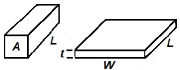
ratio of DC voltage U drop per unit length L to the surface current IS per unit width W [14]. Therefore,
we have, after simple passages, that RS = ρS L/W.The
sheet resistance and the surface resistivity are therefore different physical quantities, that have different values in the same unit of measurement.
Figure 1: This is the geometry we can use for linking volume resistivity (left) and sheetresistance (right).
The current is assumed parallel to the direction of dimension L.
The sheet resistance and the volume resistivity are related in the following manner. Let us suppose a current flowing along the direction of dimension L in the Figure 1. The resistance R is equal to ρL/A
ρL/(t⋅W), where ρis the volume resistivity. Note that t is the thickness. Let us combine resistivity and thickness in the following manner: R
(ρ/t)⋅(L/W) . Assuming R
RS⋅L/W , the quantity RS
ρ/t is thesheet resistance [15,16]. But we have also that RS
ρS⋅L/W. Therefore: ρS = (ρ⋅W)/(t⋅L). This is the link
between the surface and the volume resistivity. Let us
note that the ratio L/W is referred to the number of squares [17].
For what concerns the units of measurement, let us remember that the resistivity is given in units of Ω·m. Actually, it is Ω·m2
/m, being the dimensions of the resistivity given as [resistance·area / length]. When the resistivity is divided by the sheet thickness t (in meters), the units are Ω·m2/m/m = Ω. Therefore, the
sheet resistance can be given in ohms. However, a commonly used unit is the ohms-per-square, denoted by Ω/sq, that we have previously used for the ranges of ESD materials.
The history of ohms-per-square is discussed in [18]. In 1958, expanding the previous works of other researchers, F. M. Smits defined a four-point probe method of measuring the "sheet resistivity". His work eventually became an industry standard for measuring this resistivity in semiconductors [19]. Ten years after, in 1968, Berry, Hall and Harris stated that the resistance of a thin-film resistor is directly proportional to the resistivity ρ, and inversely proportional to the thickness t [20]. They also introduced the “sheet resistance” RS
ρ/t , addingthat it has the unit of ohms, but it is better to refer to it as “ohms per square”. The reason is that sheet resistance produces the resistance of the resistor when multiplied by the number of squares [18]. So, the term “sheet resistance” started being used in defining the materials to control ESD [18].
3. Polymers for ESD packaging
The polymer resins, because of their low cost and versatility, are the main components in the packaging used to store and transport sensitive electronics. However, due to the presence of static charges, the polymers must be turned into materials able of draining these charges and protect the devices from discharges. Therefore, the polymers must be able of conducting electricity in some extent [21]. By their nature, commercial polymers are electrical insulators, so they need being engineered to become antistatic, dissipative or conductive. This is realized either through chemical treatment or through the addition of conductive agents during the processing of polymers [21-23]. The end use of the polymer is determining the required level of conductivity. In fact, some additives simply prevent an excessive presence of static charges on the surface of the polymers. Others additives provide an ESD preventions. In addition, additives that are more conductive are involved for
RF/EMI (radio frequency electromagnetic)
interference [24].
Engineered Polymers in Packaging: Some Solutions to Prevent Electrostatic Discharge
http://www.ijSciences.com
Volume 8 – February 2019 (02)
118
one of the cheapest resins available which is showing good chemical resistance. As told in [24], without antistatic agents, polyolefins acquire static charge easily, so that troublesome spark discharges can happen, especially in dry environments (let us remember that some surface moisture can serve as a conductive means for dissipating charges). In packaging applications, in particular when controlling ESD is necessary, LDPE is modified into a carbon-filled conductive material. The filler is used to render the polymer an antistatic one.
Among the other commonly used polymers, we find the fluorinated resins and polyesters. Among the fluorinated resins, PTFE is a polymer having chemical and thermal inertness, well-known because used as a non-stick coating for pans and cookware. However, as explained in [21], it is also highly triboelectric and therefore it is often creating problems, since it is generating static charges during handling. PTFE is not found in conductive forms, but other fluorinated polymers are available with conductive fillers [21,26].
Polyester is a class of polymers that contain the ester functional group in their main chain. The most common and widely used polyester is PET, polyethylene terephthalate. PET resins show excellent chemical and moisture barrier properties and, being nontoxic, can be used for food and pharmaceutical applications. In the electronics industry, PET resins are most often found in packaging applications in which the resin is modified to be dissipative of the static charges [21].
4. Enhancing the dissipation in polymers
By their nature, without additives or fillers, commercial plastics are electrical insulators. Charges deposited on the polymer surface are living there for a long time. The longer the lifetime, the more likely is the possibility of an electrostatic event, that is, a discharge, which can cause a damage to near electronic components. The charge decay time is the rate of charge dissipation. It is given by τ
ε, where is the electric resistivity and ε the dielectric permittivity. The first quantity, the resistivity, tells us how strongly a material opposes the flow of electric current. The last quantity, the dielectric permittivity, is characterizing the ability of the material of storing
an electrical charge when subjected to an applied voltage.
About the decay time of charges, let us propose the simple explanation given in [27,28]. The Figure 2 shows a material, with the resistivity and the permittivity ε, placed on a grounded plane. A charge q is distributed on the surface of the material. If the charge density is σ, the field strength in the material is E
σ/ε. The charges can move giving the current density: j = E/ = σ/(ε). However, the current density j is also the rate at which the surface density decreases, that is: j = −dσ/dt = σ/(ε). Solving this equation we find that σ = σoexp(−t/τ), with τ = ε andσo the initial value of the charge density. In the case
of Plexiglas, 1013 ohm-meter and ε 3. 10−11 farad per meter (relative permittivity εr 3.4).
Therefore, a charge on it will decay with a time constant of about 300 seconds.
Figure 2: A material, with the resistivity ρ and the
permittivity ε, is placed on a grounded plane. A charge q is distributed on the surface of the
material.
For static charge dissipation, we must reduce the decay time τ of the charge, by enhancing conductivity and reducing permittivity. This is not a simple task, because the loading of polymers with conducting additives reduces the resistivity of polymers, and, at the same time, increases the permittivity, proportionally to the loading. Therefore, the control of ESD in polymers using fillers is a non-trivial problem.
Let us remembers that several methods exist that we can use to make polymers either static dissipative or electrically conductive. The most common methods are using some chemical additives, fillers or inherently dissipative polymers mixed in the polymer [21].
Engineered Polymers in Packaging: Some Solutions to Prevent Electrostatic Discharge
http://www.ijSciences.com
Volume 8 – February 2019 (02)
119
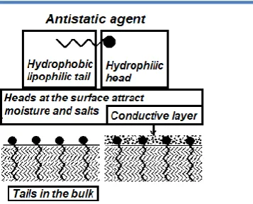
Figure 3: Antistatic molecules have both hydrophilic and hydrophobic parts. The hydrophobictail, by its good interaction with the polymer, is anchoring the molecule. The polar head attracts water and ions to form a thin conductive layer. The surface is then
electrically dissipative.
Antistatic agents are usually molecules composed by both hydrophilic and lipophilic parts. The molecules have a lipophilic tail, which has a good interaction with the polymers, and a hydrophilic head which has a good interaction with water and ions. The tail (see Fig.3) is anchoring the molecule at polymeric surface. The hydrophilic polar head attracts water and ions from environment onto the plastic surface to form a thin conductive layer. This layer allows electric charge to flow, turning the plastic film in the
dissipative regime [21]. Using such agents, the conductivity is enhanced but permittivity remains that of polymers.
Let us note that the migrating antistatic agents offer good protection for short-term applications; for other applications, that are requiring longer-term protection or a lower resistivity, conductive additives such as carbon black, conductive fibers and nanomaterials are used [29,30].
Inherently dissipative polymers (IDPs) are used too as permanent antistatic materials [29]. In fact, these polymers possess a dissipation mechanism intrinsic to their structure. Mixed in a host resin at a level of 10 to 30%, IDPs are able to lower the sheet resistance of the mixture to a range from 109 to 1012 ohm/square [21]. An example of IDP is the polyethylene oxide (PEO), whose structure is given in the Figure 4. We can see that the only difference in structure, between PEO and polyethylene, is an oxygen atom inserted between methyl groups. This oxygen atom is fundamental because changes the chemistry of the polymer. It is adding a polar character to the chain. The polarity of this atom attracts and interacts with water and ions, so that conduction can occur: ions hop from oxygen to oxygen, travelling along the PEO chain length.
Figure 4: (a) The PEO chain has on oxygen atom
inserted in the monomeric unit of PE.
Figure 4: (b) Oxygenattracts water and ions and then PEO can be used as an antistatic agent for the host polymer.
5. Fillers
A well-known method of making a plastic electrically dissipative or conductive is that of loading it with conductive fillers. Among fillers, we find micrometric metal particles, metal and carbon fibers and carbon powders or carbon blacks. Carbon black (CB) is a relatively inexpensive and easily processable filler material for ESD. It is formed by burning hydrocarbons in a limited oxygen environments [24]. This material has been produced and marketed for more than a century without significant changes to its physicochemical properties. Its main application is used in rubber applications, then it is used for pigments and, in a small quantity, for other applications.
Engineered Polymers in Packaging: Some Solutions to Prevent Electrostatic Discharge
http://www.ijSciences.com
Volume 8 – February 2019 (02)
120
ohm·cm, that can be suitable for EMI shielding. However, high conductive composites can be manufactured with carbon black too, such as CB-filled high-density and low-density polyethylene and polypropylene [31,32].
The filler loading of the polymer is very important for the final conductivity. For low filler loading, the composite conductivity remains undisturbed because the host resin electrically insulates the filler particles. Increasing the filler loading, the material reaches the "percolation threshold" where the resistivity suddenly drops. At this loading value, the conductive particles are more likely to come into contact with each other and then create a continuous conductive network in the polymer in which the electric current percolates. Additional filler loading beyond the percolation threshold is not necessary and does not increase the conductivity. In Ref.31, for instance, it is shown that using a 2 wt% of carbon black within HDPE, the CB particles are building a conductive network, which lead to high conductivity.
In creating a connected network, the shape of particles has a crucial role. Spherical fillers require as much as 40% by volume loading in order to reach the percolation threshold whereas a more elaborate shape
can strongly reduce the threshold value. From this point of view, carbon-black is good since it is able to form wide and long branched agglomerations. Let us stress that different electrical percolation thresholds of the composites are found for the different species of carbon black used in them. Carbon blacks with the lowest packing efficiency reach the percolation threshold with the least volume fraction of carbon black loading [33].
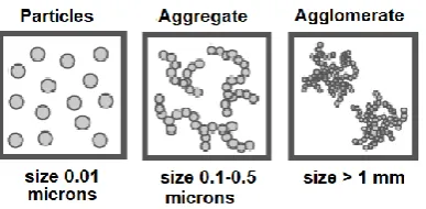
Observing the carbon black particles under an electron microscope [34,35], we can see that their structure is made by several spherical particles, the primary particles or nodules, which are fused together in aggregates (see Figure 5). Various functional groups such as the hydroxyl or carboxyl group are found in the surface. The size of the particles, their structure and chemistry of the surface have a large effect on practical properties of carbon black. The most important factor influencing the electrical conductivity of a compound containing CB is its structure. A high structure is that ideal for conductive compounds. High structure means that the aggregates are forming agglomerates having long and branched chains (Figure 5) [36].
Figure 5: Carbon black is made of primary particles (nodules), which form aggregates. In them, there is a
strong bond between primary particles. The aggregates are then creating the agglomerates. Between the agglomerates there are weak bonds.
Carbon black particles and the short carbon fibers (SCF) are the most commonly used conductive components for polymers. The carbon fibers can be considered as chain-like aggregates of carbon particles having long chain length [37]. However, CB and SCF exhibit different behaviours in creating a conductivity in the polymers due to their different natures [37]. For instance, the loading for the onset of the insulator to conductor transition is higher for the particle-filled composite. These differences can be attributed to the fact that the fibrillar form of the SCF has a higher tendency to form a network in the composites, resulting in a better electrical conductivity than the CB filler [37]. Moreover, the carbon black surface has a chemistry due to the presence of active groups on them, which are prone
to capture electrons and reduce conductivity [37]. The carbon fibers do not possess such groups on their surface, because of the high temperature required during their manufacture.
6. Carbon nanotubes as nanofillers
Carbon atoms are unique because they are able to form many different structures, when they bond with other carbon atoms. In nature, we find pure carbon in solid state as diamond and graphite. Graphite is layered. In diamond, carbon atoms are arranged in a three-dimensional tetrahedral structure. Graphite is a good electrical conductor but diamond is a good insulator: this is because of the respective structures which can have different electric conductivities.
Engineered Polymers in Packaging: Some Solutions to Prevent Electrostatic Discharge
http://www.ijSciences.com
Volume 8 – February 2019 (02)
121
The carbon nanotubes have a high aspect ratio (they are very long and their diameter are small), meaning that the conductive network is established with a very low loading of the polymer, compared to other fillers [42]. It means that the resistivity ρ drops, but the permittivity ε does not rise, because the loading is small. Therefore, the nanotubes are fillers giving a very low time constant τ that is, a fast rate of discharge. For what concerns the relative permittivity, let us remember that for unfilled polymers, it is about 3. For a metal, it has a very large value. Therefore, if a polymer is loaded with some metallic particles, its relative permittivity increases. This is easy to understand if we consider the effective electrical properties of such mixture as proportional and linear to the concentrations and dielectric permittivities of constituents [43,44]. In the case of the nanotubes, they are like a sort of unidimensional material inserted in a three-dimensional volume. Then, we can have a very low percolation threshold (for instance 0.3 wt%, [45]). In this manner, we increase the conductivity, without increasing the relative permittivity, because such a small loading does not affect it.
The use of carbon nanotubes for ESD polymers is adding the costs for studying and preparing them. However, these costs seem being compensated because the use of nanotubes as filler reduces the detrimental effects observed when high loading of conductive particles are involved. Low loading means good retention of physical properties of packaging and an excellent surface quality of polymers. Several companies worldwide exist producing nanotubes, in multi walled nanotubes [46].
Besides those above-mentioned, there are other costs we have to consider too. These costs are those necessary to study the toxicity of CNTs themselves, to avoid they could cause problems like those of previous industrial products such as asbestos, PCBs and freons [47]. As stressed in [48], researches which can give both the quantification of free nanoparticle release and the eventual toxicity of them are urgently needed.
7. Specific Issues
Let us conclude mentioning some recent studies on polymers composites. In [49], we can find a review about the use of carbon - carbon black, graphite, graphene, fullerenes, carbon nanotubes, etc. - in numerous applications as a filler in the polymer composite. As told by the authors, they discuss in details many applications; among them we find ESD and EMI shielding. Besides this article, let us also mention a book on conducting polymers [50].
Among specific issues, we have Refs. [51],[52] and [53]. In [51], the research is concerning a study to understand if PET compounds with carbon black can be uses to replace polypropylene and polystyrene for anti-static packaging materials. The researchers concluded that the compound based on PET filled with 15.0% carbon black might be used in the handling, transportation and storage of electronic components. In [52], the use of the polylactic acid PLA, a biodegradable polymer obtained from renewable sources, is discussed for antistatic packaging. PLA has no conductive characteristics and therefore it requires the addition of allotropic carbon forms, such as the conductive carbon black. In [52], the researchers studied PLA with carbon black. The addition of carbon black makes the composite less resistive and suitable for use as antistatic packaging for the transportation and storage of electronic components. As stressed by the authors [52], this composite does not cause damage to the environment as the carbon black does not interfere in the degradation mechanism of PLA.
In [53] it is shown how nanocomposites with addition of graphite nanoparticles, multi-walled carbon
nanotubes (MWCNTs), and graphene in
cyanoacrylate can be fabricated. The experimental studies tell that, compared with graphene and graphite nanofillers, MWCNTs is the best filler to be used in cyanoacrylate in thermal and electrical conductivity enhancement at low filler loading.
In concluding this article, we want to stress a problem regarding hazards related to electrostatic charges. This issue is also evidencing further applications of polymers engineered for preventing electrostatic discharges, besides the use in packaging.
In [54], the researchers investigated the charge generated on bedclothes, made by cotton and polyester, during bedding exchange, to identify the hazards of electrostatic shocks and ignitions occurring in medical facilities. After their studies, the authors stress that grounding of human bodies via footwear and flooring is essential to avoid such hazards.
References
1. Gooding, D. M., & Kaufman, G. K. (2011). Tribocharging and the Triboelectric Series, In Encyclopedia of Inorganic and Bioinorganic Chemistry, John Wiley & Sons, Ltd. DOI: 10.1002/9781119951438.eibc2239
2. Henniker, J. (1962). Triboelectricity in polymers. Nature, 196(4853), 474. DOI: 10.1038/196474a0
3. Freeman, G. R., & March, N. H. (1999). Triboelectricity and some associated phenomena. Materials science and
technology, 15(12), 1454-1458. DOI:
10.1179/026708399101505464
Engineered Polymers in Packaging: Some Solutions to Prevent Electrostatic Discharge
http://www.ijSciences.com
Volume 8 – February 2019 (02)
122
URL: http://electronicdesign.com/power/understanding-esd-and-eos-failures-semiconductor-devices
5. Németh, E., Albrecht, V., Schubert, G., & Simon, F. (2003). Polymer tribo-electric charging: dependence on thermodynamic surface properties and relative humidity. Journal of Electrostatics, 58(1-2), 3-16. DOI: 10.1016/s0304-3886(02)00137-7
6. Drobny, W. A. (2007). Handbook of Thermoplastic Elastomers, William Andrew Editor. ISBN 9780323221368 7. Sparavigna, A. C. (2008). Antistatic polymers for packaging.
Converter: Flessibili, Carta, Cartone, 70, 38-45.
8. Avloni, J., Lau, R., Ouyang, M., Florio, L., Henn, A. R., & Sparavigna, A. (2008). Polypyrrole-coated nonwovens for electromagnetic shielding. Journal of Industrial Textiles, 38(1), 55-68. DOI: 10.1177/1528083707087834
9. Ohring, M. (1992). The Materials Science of Thin Films, Academic Press. ISBN 9780125249751
10. Volume and Surface Resistivity Measurements of Insulating Materials Using the Model 6517A Electrometer/High Resistance Meter. Keithley. URL: http://four-point-probes.com/volume_surface.pdf
11. Blythe, A. R. (1984). Electrical resistivity measurements of polymer materials. Polymer Testing, 4(2-4), 195-209. DOI: 10.1016/0142-9418(84)90012-6
12. Aminabhavi, T. M., Cassidy, P. E., & Thompson, C. M. (1990). Electrical resistivity of carbon-black-loaded rubbers. Rubber chemistry and technology, 63(3), 451-471. DOI: 10.5254/1.3538265
13. Cvetko, B. F., Brungs, M. P., Burford, R. P., & Skyllas-Kazacos, M. (1987). Conductivity measurements of electrodeposited polypyrrole. Journal of applied
electrochemistry, 17(6), 1198-1202. DOI:
10.1007/bf01023603
14. Maryniak, W. A., Uehara, T., & Noras, M. A. (2003). Surface resistivity and surface resistance measurements using a concentric ring probe technique. Trek Application Note, 1005, 1-4.
15. Haider Khaleel (2014). Innovation in Wearable and Flexible Antennas, WIT Press. ISBN 9781845649869
16. Chung, D.D.L. (2010). Functional Materials: Electrical, Dielectric, Electromagnetic, Optical and Magnetic Applications, World Scientific Publishing Company. ISBN 9789814287159
17. Madou, M. J. (2002). Fundamentals of Microfabrication: The Science of Miniaturization, Second Edition. CRC Press, Mar 13, 2002. ISBN 9781482274004
18. Chase, G. (2004). Ohms per square What! ESD Journal, The
ESD & Electrostatics Magazine. URL:
http://www.esdjournal.com/techpapr/ohms.htm
19. Smits F. M. (1958). Measurement of sheet resistivities with the four-point probe, Bell System Technical Journal, May 1958, 711-718. DOI: 10.1002/j.1538-7305.1958.tb03883.x 20. Berry, R. W., Hall, P. M., & Harris, M. T. (1968). Thin Film
Technology, Van Nostrand Reinhold Company, New York. 21. Rosner, R. B. (2001). Conductive Materials for ESD
Applications: An Overview, IEEE Transactions on Device
and Materials Reliability, 1, 9-16. DOI:
10.1109/7298.946455
22. Patel, N. C., & Balfour, K. G. (2003). U.S. Patent No. 6,528,572. Washington, DC: U.S. Patent and Trademark Office.
23. Zarras, P., & Irvin, J. (2002). Electrically active polymers. Encyclopedia of Polymer Science and Technology. DOI: 10.1002/0471440264.pst107
24. Tolinski, M. (2015). Additives for Polyolefins: Getting the Most out of Polypropylene, Polyethylene and TPO, William Andrew Editor. ISBN: 9780323358842
25. Kaminsky, W. (2004). Polyolefins. In Handbook of Polymer Synthesis (pp. 11-82). CRC Press. ISBN 9781420030594 26. Novel fluoropolymers with improved characteristics (2002).
Patent WO 2002000741 A1. URL:
https://www.google.com/patents/WO2002000741A1?cl=en
27. Jonassen, N. (2000). How fast does a charge decay. Compliance Engineering, 17, 2.
28. Jonassen, N. (2012). How fast does a charge decay. Posted
online, July 1, 2012. URL:
http://incompliancemag.com/article/how-fast-does-a-charge-decay/
29. Markarian, J. (2008). New developments in antistatic and conductive additives. Plastics, Additives and Compounding, 10(5), 22–25. DOI: 10.1016/S1464-391X(08)70172-7 30. Gornicka, B (2010). Antistatic properties of nanofilled
coatings. Acta Physica Polonica A
31. 117 (5): 869–872. DOI: 10.12693/aphyspola.117.869 32. Yuan, Q., Bateman, S. A., & Wu, D. (2010). Mechanical and
conductive properties of carbon black-filled high-density polyethylene, density polyethylene, and linear low-density
33. polyethylene. Journal of Thermoplastic Composite Materials, 23(4), 459-471. DOI:
34. 10.1177/0892705709349318
35. Yuan, Q., Wu, D. (2010). Low percolation threshold and high conductivity in carbon black filled polyethylene and polypropylene composites. J. Appl. Polym. Sci., 115: 3527– 3534. DOI: 10.1002/app.30919
36. Chung, K. T., Sabo, A., & Pica, A. P. (1982). Electrical permittivity and conductivity of carbon black-polyvinyl chloride composites. Journal of Applied Physics, 53(10), 6867-6879. DOI: 10.1063/1.330027
37. Three Main Properties of Carbon Black. Mitsubishi
Chemical. URL:
http://www.carbonblack.jp/en/cb/tokusei.html
38. International Carbon Black Association. URL: http://carbon- black.org/images/docs/2016-ICBA-Carbon-Black-User-Guide.pdf
39. Conductive Carbon Black. Premix. URL:
http://www.premixgroup.com/product-cats/conductive-compounds/conductive-carbon-black/
40. Zhang, W., Dehghani-Sanij, A. A., & Blackburn, R. S. (2007). Carbon based conductive polymer composites. Journal of materials science, 42(10), 3408-3418. DOI: 10.1007/s10853-007-1688-5
41. Sparavigna, A. (2006). Lattice specific heat of carbon nanotubes. Journal of Thermal Analysis and Calorimetry, 93(3), 983-986. DOI: 10.1007/s10973-007-8549-y
42. Sparavigna, A. C. (2014). Some Notes on Boltzmann and Landauer Phonon Thermal Transport at Nanoscale. International Journal of Sciences, 3(12), 24-27. DOI: 10.18483/ijsci.604
43. Vv. Aa. (2016). Timeline of carbon nanotubes. Wikipedia URL:
https://en.wikipedia.org/wiki/Timeline_of_carbon_nanotubes 44. Iijima, S. (1991). Helical microtubules of graphitic carbon.
Nature 354, 56-58. DOI: 10.1038/354056a0
45. Designing for ESD Protection Using FIBRIL™ Nanotubes in
Polymer. Hyperion Catalysis. URL:
http://www.hyperioncatalysis.com/PDFs/Designing%20for% 20ESD.pdf
46. Gladstone, J. H., & Dale, J. T. (1863). Researches on the refraction, dispersion and sensitiveness of liquids. Philosophical Transactions of Royal Society of London, 153:317–343.
47. Tuncer, E., Serdyuk, Y. V., & Gubanski, S. M. (2001). Dielectric mixtures--electrical properties and modeling. arXiv preprint cond-mat/0111254.
48. Zhang, X., Yan, X., He, Q., Wei, H., Long, J., Guo, J., Gu, H., Yu, J. Liu, J., Ding, D., Sun, L., Wei, S., & Guo, Z. (2015). Electrically conductive polypropylene nanocomposites with negative permittivity at low carbon nanotube loading levels. ACS applied materials & interfaces, 7(11), 6125-6138. DOI: 10.1021/am5082183
Engineered Polymers in Packaging: Some Solutions to Prevent Electrostatic Discharge
http://www.ijSciences.com
Volume 8 – February 2019 (02)
123
50. Minimizing the environmental impacts of carbon nanotubes. MIT 2008. URL: https://cee.mit.edu/onbalance/2008/october 51. Schlagenhauf, L., Buerki-Thurnherr, T., Kuo, Y. Y.,
Wichser, A., Nüesch, F., Wick, P., & Wang, J. (2015). Carbon Nanotubes Released from an Epoxy-Based Nanocomposite: Quantification and Particle Toxicity. Environmental Science & Technology, 49(17), 10616-10623. DOI: 10.1021/acs.est.5b02750
52. Bhadra S., Rahaman M., Noorunnisa Khanam P. (2019) Electrical and Electronic Application of Polymer–Carbon Composites. In: Rahaman M., Khastgir D., Aldalbahi A. (eds) Carbon-Containing Polymer Composites. Springer Series on Polymer and Composite Materials. Springer, Singapore. DOI: 10.1007/978-981-13-2688-2_12
53. Chandrasekhar, P. (2018). Conducting Polymers, Fundamentals and Applications: Including Carbon Nanotubes and Graphene. Springer. ISBN 9783319693781
54. Mesquita A.S., de Andrade e Silva L.G., de Miranda L.F. (2018) Mechanical, Thermal and Electrical Properties of Polymer (Ethylene Terephthalate—PET) Filled with Carbon
Black. In: Li B. et al. (eds) Characterization of Minerals, Metals, and Materials 2018. TMS 2018. The Minerals, Metals & Materials Series. Springer, Cham. DOI: 10.1007/978-3-319-72484-3_64
55. Silva, T. F. D., Menezes, F., Montagna, L. S., Lemes, A. P., & Passador, F. R. (2019). Preparation and characterization of antistatic packaging for electronic components based on poly (lactic acid)/carbon black composites. Journal of Applied Polymer Science, 47273. DOI: 10.1002/app.47273
56. Teoh, HC., Yaacob, K.A., Saad, A.A., & Mariatti, M. (2018). Enhancement of thermal and electrical conductivities of cyanoacrylate by addition of carbon based nanofillers. J Mater Sci: Mater Electron 29(12), 9861-9870. https://doi.org/10.1007/s10854-018-9027-y
57. Endo, Y., Ohsawa, A., & Yamaguma, M. (2019). Electrostatic hazards of charging of bedclothes and ignition in medical facilities. International Journal of Occupational
Safety and Ergonomics, 25(1), 35-39. DOI: