Volume 3, Special Issue 1, ICSTSD 2016
Effect Of Staircase On Seismic Performance Of
Multistoried Frame Structure
Ankit R. Shelotkar PG Student, Civil Department,
PRMITR, Badnera Amravati-444701, India [email protected]
Mayur A. Banarase Asst. Professor, Civil Department,
PRMITR, Badnera Amravati-444701, India [email protected]
Abstract — In this paper, the effects of staircase during the
seismic performance of Multistoried Frame Structure at Center location in plans have been studied. Generally, the staircase is the part of secondary system of the structures and it is one of the essential parts of a building because of its functional importance. Staircase when compared to the modern escalators serves not only better in emergency conditions (such as fire escapes, natural disaster, etc.) but also provides considerable stiffness to the building. Due to the complex modeling of the staircase, it is designed separately for non-seismic and seismic forces. But during earthquake as we construct the structure with staircase monolithically, staircase also contributes its performance of the building, due to this structural discontinuity, performance of buildings may result in non-linear behavior. Because of this non-linear behavior, modification in various seismic parameters such as a reduction in the time period and story drift of the building is essential. It can be concluded that the effect of a staircase in the analysis and design of RC frame buildings cannot be ignored. In the present study, the effect of staircase position on RC frame structures has been carried out by adopting various building models with and without staircase in longitudinal and transverse direction. The Linear Response Spectrum analysis of the models has been carried out as per IS: 1893 (Part 1) - 2002 and IS: 456 – 2000 with the help of Etab 2015 software. The Seismic characteristics in terms of Time period, Story Drift and Story Displacement have been compared with the seismic characteristics of models with and without a staircase. Further, the effect of change in location of the staircase on the behavior of the building has also been observed. In addition to these, short column effect, variation in moments of beams and columns that are attached to staircase slab, failure and deformation in staircase models have also been studied.
Keywords: Story drift, Story displacement, Response spectrum analysis, Short column effect, Time period.
I. INTRODUCTION
An earthquake is a spontaneous event and behaves quite differently. The force generated by the seismic action of an earthquake is different than other types of loads, such as gravity and wind loads. It strikes the weakest spot in the whole three dimensional building. Ignorance in design and poor quality of construction result, many weaknesses in the structure, thus cause serious damage to life and property. The staircase is the part of secondary system of the structures and it is one of the essential parts of a building because of its
functional importance. Due to the complex modeling of the staircase, it is designed separately for non-seismic and seismic forces. From a geometrical point of view, a stair is composed of inclined element (beam and slabs) and by short column. These elements contribute to increase stiffness of the building. The effect of the staircase on the RC frame structure found in literature may be summarized as imparting discontinuity in the modeling, variation in failure of allied structural elements, contributing in non-linear performance of buildings, modification of various seismic parameters such as reduction in the time period, story drift, and story displacement of the building have been considered in this study. Hence it can be suggested that the effect of a staircase in the analysis and design of RC frame buildings cannot be ignored.
II. BUILDINGMODELING
Volume 3, Special Issue 1, ICSTSD 2016 A. The details of the modeled building are listed below:
Plan dimensions 25 X 21.8 m(X*Y) Length in X- direction 25 m
Length in Y- direction 21.8 m Floor to floor height 3.2 m
No. of Stories 8
Edge Beam 0.3 X 0.45 m
Total height of Building 25.6 m Slab thickness (S1) 0.155 m Inclined slab thickness (S2) 0.130 m
Edge Beam 0.3 X 0.45 m
Column size 0.45 X 0.45 m External and internal wall thickness 0.30 m Grade of concrete M30 Grade of steel Fe 415
Seismic zone III
Soil Type II
Importance factor 1 Building frame type SMRF Density of concrete 25 KN/m3 Density of masonry wall 20 KN/m3
B. Loading Considered:
Live load on floor is 5kN/m2
Live load on roof is 4 KN/m2
Floor Finish is 2KN/m2
Floor finish on roof is 4 KN/m2
Wall Load = 16.5 KN / m
Parapet Wall Load=6 KN / m
III. RESULTS &DISCUSSION
Comparison of all models prepared in Etab carried out with the help of graph. In Case Study 1 , buildings A1 and B1 with G+7 storey are modeled in (X-Dirt.) is analysis and study the various parameters. Similarly, in Case study 2, buildings A2 and B2 with G+7 are modeled in (Y-Dirt.) and analysis is done to study various parameters such as storey drift and storey displacement, bending moment, area of steel, time period.
A. RESULT FOR MODELS A-1 AND B-1 TYPE OF BUILDING (Case Study 1)
A. Comparison of storey displacement
Fig. 1. Comparison of Max storey displacement (X-Direction)
Fig. 2. Comparison of Max storey displacement (Y -Direction)
From Fig.1 It is observed that storey displacement in X-direction for B1 frame is averagely 2-3% greater than that for A1 RC frame.
From Fig.2 It is observed that storey displacement in Y-direction for B1 frame is averagely 13-14 % greater than that for A1 RC frame.
C. Comparison of storey drift
Fig 4 - Comparison of Max storey drift (Y-Axis) (mm) Fig. 3. Comparison of Max storey drift (X-Axis) (mm)
Fig. 4. Comparison of Max storey drift (Y-Axis) (mm)
From Fig. 3 It is observed that storey drift in X-direction for B1 frame is averagely 3-4% greater than that for A1 RC frame.
Volume 3, Special Issue 1, ICSTSD 2016 C. Comparison of Time period
Fig. 5. Comparison of Max Time Period X-Dirt. (W & Wo)
It is observed that the time period of without stair model is more than a with stair model. The difference between the two time period varied by 1 % for longitudinal direction.
D. Comparison of design load for column
Fig. 6. Comparison of design load for column C41
Fig. 7. Comparison of design load for column C22
Fig. 8. Comparison of design load for column C37
From Fig. 6 It is observed that design load in C41 for A1 frame is averagely 4% greater than that for B1 RC frame at GS.
From Fig. 7 It is observed that design load in Column C22 for A1 frame is averagely 3% greater than that for B1 RC frame at GS.
From Fig. 8 It is observed that design load in Column C37 for B1 frame is averagely 6% greater than that for the A1 RC frame at GS.
E. Comparison of shear force for columns
Fig. 9.Comparison of shear force for column C41
Fig. 10. Comparison of shear force for column C22
Fig. 11. Comparison of shear force for column C37
From Fig. 9 It is observed that shear force in C41 for B1 frame is averagely 4-5% greater at 1S storey than that for A1 RC frame.
From Fig.10 It is observed that shear force in Column C22 for A1 frame is averagely 2-3% greater at GS storey than that for B1 RC frame.
Volume 3, Special Issue 1, ICSTSD 2016 F. Comparison of bending moment for columns
Fig. 12. Comparison of bending moment for column C41
Fig. 13. Comparison of bending moment for column C22
Fig. 14.Comparison of bending moment for column C37
From Fig. 12 It is observed that bending moment in C41 for A1 frame is averagely 10% greater than that for B1 RC frame at 7S.
From Fig. 13 It is observed that bending moment in Column C22 for A1 frame is averagely 52% greater than that for B1 RC frame at 3S.
From Fig. 14 It is observed that bending moment in Column C37 for A1 frame is averagely 22% greater than that for B1 RC frame at 1S.
B . RESULT FOR MODELS A-2 AND B-2 TYPE OF BUILDING (Case Study 2)
A. Comparison of storey displacement
Fig. 15. Comparison of storey displacement (X-Direction)
Fig. 16. Comparison of storey displacement (Y-Direction)
From Fig 15. It is observed that storey displacement in X-direction for B2 frame is averagely 14-15% greater than that for A2 RC frame.
From Fig 16. It is observed that storey displacement in Y-direction for B2 frame is averagely 3-4% greater than that for A2 RC frame.
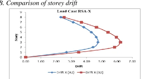
B. Comparison of storey drift
Volume 3, Special Issue 1, ICSTSD 2016
Fig. 18. Comparison of storey drift (Y-Axis) (mm)
From Fig. 17. It is observed that storey drift in X-direction for B2 frame is averagely 23-24% greater than that for the A2 RC frame.
From Fig 18. It is observed that storey drift in Y-direction for B2 frame is averagely 4-5% greater than that for the A2 RC frame.
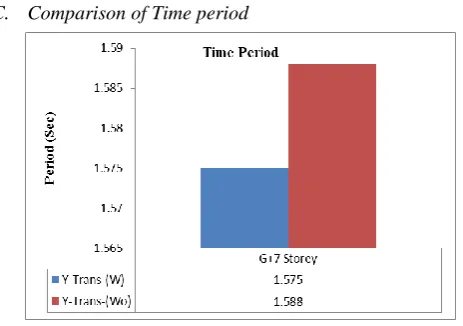
C. Comparison of Time period
Fig. 19. Comparison of Time Period X-Dirt. (W & Wo)
It is observed that the time period of without stair model is more than a with stair model. The difference between the two time period varied by 0.8 %.
D. Comparison of design load for column
Fig. 20. Comparison of design load for column C1
Fig. 21.Comparison of design load for column C16
Fig. 22.Comparison of design load for column C37
From Fig. 20. It is observed that design load in C1 for A2 frame is almost same that for B2 RC frame.
From Fig. 21. It is observed that design load in Column C16 for A2 frame is averagely 2% greater than that for B2 RC frame.
From Fig. 22. It is observed that design load in Column C37 for A2 frame is averagely 3% greater than that for B2 RC frame.
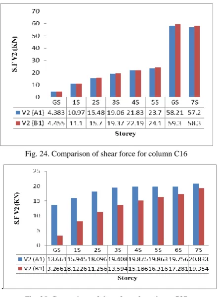
E. Comparison of shear force for columns
Volume 3, Special Issue 1, ICSTSD 2016
Fig. 24. Comparison of shear force for column C16
Fig, 25. Comparison of shear force for column C37
From Fig 23. It is observed that shear force at 7S in C1 for A2 frame is almost same for B2 RC frame.
From Fig 24. It is observed that shear force in Column C16 for B2 frame is averagely 2% greater at 6S storey than that for A2 RC frame.
From Fig 25 It is observed that shear force in Column C37 for A2 frame is averagely 6% greater than that for B2 RC frame.
F. Comparison of bending moment for columns
Fig. 26.Comparison of bending moment for column C1
Fig. 27.Comparison of bending moment for column C16
Fig. 28.Comparison of bending moment for column C37
From Fig. 26 It is observed that bending moment in C1 for A2 frame is almost same for B2 RC frame.
From Fig. 27 It is observed that bending moment in Column C16 for B2 frame is averagely 2% greater than that for A2 RC frame.
From Fig. 28 It is observed that bending moment in Column C37 for A2 frame is averagely 3% greater than that for B2 RC frame.
IV. CONCLUSION
From the study made and the results presented in the previous sections, the following important conclusions have been drawn within the preview of the buildings considered.
It is observed that the presence of staircase tremendously influence the peak value of result of beams and columns around staircase obtained after analysis.
It is observed that in (Case study 1) storey drift in longitudinal direction model, without stair (B1) model is averagely 4% greater than with stair (A1) model for X-dirt. and without stair (B1) model is averagely 22-23% greater than with stair (A1) model for Y-dirt.
It is observed that in (Case study 2) storey drift in transverse direction model, without stair (B2) model is averagely 24% greater than with stair (A2) model for X-dirt. and without stair (B2) model is averagely 5% greater than with stair (A2) model for Y-dirt.
Volume 3, Special Issue 1, ICSTSD 2016
It is observed that in (Case Study 1) storey displacement in the longitudinal direction model, without stair (B1) model is averagely 3% greater than with stair (A1) model for X-dirt. And without stair (B1) model is averagely 14 % greater than with (A1) stair model for Y-dirt.
It is observed that in (Case Study 2) storey displacement in the transverse direction model, without stair (B2) model is averagely 15% greater than with stair (A2) model for X-dirt. And without stair (B2) model is averagely 15 % greater than with (A2) stair model for Y-dirt.
Columns supporting landing beam have been found to be subjected to an increase in axial force for with stair model by an averagely 6% and he lateral moment in such columns increased on averagely by 22% for with stair model for (Case study 1)
Columns supporting landing beam have been found to be subjected to an increase in axial force for with stair model by an averagely 3% and the lateral moment in such columns increased on averagely by 3% for with stair model for (Case study 2)
Columns other than staircase room have been found to be subjected to an increase in axial force by an average of 3%. The lateral moment in such columns increased on an average by 52% for longitudinal dirt. (Case study 1)
Columns other than staircase room have been found to be subjected to an increase in axial force by an average of 3%. The lateral moment in such columns increased on an average by 52% for transverse dirt (Case study 2)
It is observed that time period for without stair (wo) model is more than that of with stair (w) model in longitudinal and transverse direction (Case Study 1 & 2) the time period varies by 1% and 0.8% respectively.
If building and there components are not design properly by considering diagonal effect of staircases, it may get fail under major earthquakes
References
[1] N Shyamananda Singh, And S Choudhury, “Effects Of Staircase On The Seismic Performance Of Rcc Frame Building” International Journal of Engineering Science and Technology (IJEST), ISSN : 0975-5462 Vol. 4No.04 April 2012.
[2] Huanjun Jiang, Haiyan Gao and Bin Wang, “Seismic damage analyses of staircases in RC frame structures” Advanced Materials Research Vols. 446-449 (2012) pp 2326-2330.
[3] Pratik Deshmukh , M.A. Banarase, “Effects Of Staircase On Seismic Performance Of Rc Frame Buildings” International Journal of Current Engineering and Technology, Vol.5, No.3 (June 2015).
[4] EdoardoCosenza , Gerardo Mario Verderame , Alessandra Zambrano, “Seismic Performance Of Stairs In The Existing Reinforced Concrete Building”, World Conference on Earthquake Engineering October 12-17, 2008, Beijing, China.
[5] Bixiong Li and Khalid M. Mosalam ,Xuan Wang, Zhou Wei,” Analysis of stairwells performance and damage during Wenchuan earthquake” World Conference on Earthquake Engineering October 12-17, 2008, Beijing, China
[6] Ioannis A. Tegos, Vassilis P. Panoskaltsis and Sevasti D. Tegou “Analysis And Design Of Staircases Against Seismic Loadings”Kos Island, Greece, 12–14 June 2013.
[7] Zhi-Wei CAO, Chen BIAN, Chun-Yi XU , “Analysis of the Interaction between Stair and Frame under Horizontal Earthquake Action Based on ETABS ”, International Conference on Mechanics and Civil Engineering (ICMCE 2014).