Advanced Ceramics Progress
J o u r n a l H o m e p a g e : w w w . a c e r p . i r
Simulation of the Effect of Sub-Micron Interface Roughness on the Stress
Distribution in Functionally Graded Thermal Barrier Coatings
N. Nayebpashaee a,*, S.H. Seyedeina, M. R. Aboutalebia, H. Sarpoolakya, M.M. Hadavib
aDepartment of Materials and metallurgical Engineering, Iran University of Science and Technology (IUST), Tehran, Iran bMetallic materials research center, Malek Ashtar University of Technology, Tehran, Iran
P A P E R I N F O
Paper history: Received 03 January 2015
Accepted in revised form 10 February 2015
Keywords:
Finite element method
functionally graded thermal barrier coating sinusoidal interface
Residual stress
A B S T R A C T
In this research, a numerical modeling method was utilized to calculate the stresses occurring during the thermal cycling in a functionally graded thermal barrier coating (FG - TBC). The temperature – dependent material response of this protective material was taken into account and the effects of the thermal cycle and interface morphology of the ceramic /metallic layer in a functionally graded coating system was investigated. Sinusoidal mode of asperity with specific wavelength and amplitude was used to model the two dimensional geometry of interface profile between layers. A finite element model was used to model the effect of the thermal loading imposed on the thermo-mechanical response and stress distribution. In this regard, different observable facts were taken into account in the model such as: non- homogenous temperature distribution, periodic boundary condition and convective heat transfer. These phenomena depict the most real world situation in numerical simulation of multi-layer coating during cooling and thermal cycling, specifically near the ceramic/metal interface. In addition, regions which are potent to crack initiation and propagation in the system and the subsequent delamination places of the TBCs system were predicted.
1. INTRODUCTION1
In aerospace and turbine industry, achieving higher efficiency for aircraft engines working in high temperatures has always been an important issue to engineers. Higher efficiency means tolerating quite higher elevated temperatures in sensitive components and parts of internal combustion engines[1]. Thermal barrier coatings (TBCs) are one of the advantageous materials widely used as insulation materials to protect the underlying metallic structure of a gas turbine blade form thermal damages And to increase its lifetime. The typical TBC is composed of double layers including the bond coat and top coat. The bond coat is MCrAlY (where M = Ni and/or Co)and the ceramic-based top-coat is often made of yttria stabilized zirconia (YSZ)[1]. The search for new materials has been intensified in the last decades. As a result, zirconate-based TBCs are expected to be the candidate materials for the future application in aircrafts, turbines and other high temperature components due to their low thermal conductivity, high stability and high sintering resistance ability at high temperature. La2Zr2O7 (LZ) is one of the
1*Corresponding Author’s Email: [email protected] (N. Nayebpashaee)
candidate materials. So far, little investigation has been carried out on the thermal shock behavior of the double-ceramic-layer TBCs [2-4].
Some of the main threats to durability these coatings are as follow: residual stresses stemmed from technical process, mismatch between different materials in layers and finally compound and rough character of the TBC/BC boundary [5]. Residual stresses can occur in three places in real conditions of application which are stresses induced during phase transformation, solidification and further contraction of splat droplets from spraying temperature to the room temperature and the origin of such stress is the difference between the linear Coefficient of Thermal Expansion of two materials at two side of interfaces in substrate / BC or BC / TC. This matter is worse and more hazardous when the coating system is cooling down from high temperatures to ambient temperatures, drastically decreasing the lifetime of protective layer [5].
None the less, it advances the adhesive property and can considerably increase the efficient lifetime of a plasma-sprayed coating system imposed by thermal cycling. On the other hand, non- flat surfaces are more conducive to non- uniform stress distribution and stress concentration than to flat surfaces which can lead to existence of more crack initiation dangerous zones [6].
One of the conventional phenomena resulting in failure of TBC systems is the growth of thermally growth oxides with different thicknesses and morphologies. At higher temperatures and at the interface of BC/TC, diffusion is activated and simultaneous migration of aluminum and oxygen take place, gradually leading to formation of aluminum oxide layer that usually shapes a hinder and constraint expansion. Resistance to free expansion and even contraction induces residual stress at boundary zones and exposing them to the risk of crack initiation and further propagation.
This is a major failure mechanism developed at the interface formed as a result of bond coat oxidation at about 900oC. The effect of formation of this oxide layer was investigated and several parametric study was done considering alumina oxide layer, interface shape morphology and non- homogeneity of thermal loading as affecting parameters of TBC performance [7]. Another important limitation in this high temperature protective system is the interfaces between substrate/BC and BC/TC. These interface regions undergo high stresses due to the mismatch among thermal expansion between materials and also due to interface between sub- micron roughness [8].
These categories of coatings comprise a conventional top coat and a metallic bond coat as well as intermediate coatings with different quantities of ceramic and metallic constituents. It is worth noting that, stress mismatch at the interface and various defects in the coating materials can be reduced by replacing the sharp interface composition with a graded composition layer. In this kind of materials, the micro structure and properties change from ceramic to metal gradually from ceramic region to metal region and enhance adhesion and fatigue life in addition to residual stress decrease [9- 10 ].
The presence of an intermediate layer between surface ceramic and metallic layer causes outstanding increase in hot corrosion of coating system [11]. The existence of Cr and Al in composite layer of BC + TC leads to the formation of AlVO4 and CrVO4 as other products of hot
corrosion that reduces the contact area of YSZ with molten salt and less reaction takes place between them. The consequence of that can be considered to be less extensive in the transformation phase in zirconia, reducing volume change and inducing stresses and better lifetime of TBC [12].
In addition, the thermal fatigue life of functionally graded coatings is approximately five times better than conventional coating with identical thickness and also better oxidation resistance was seen FG–TBC protective layers [13].
Several finite element simulations regarding different aspects of process such as solidification stress, splatting impact, TGO and layer thickness, configuration, time and kinetics of formation and location, interface asperity and thermal shock were studied [14-20].
The purpose of the current study was to assess the influence of the sub- micron interfaces roughness on stress distribution in finite element ABAQUS commercial code of functionally graded TBC systems. FE modeling of TBC systems on functionally graded thermal barrier coating is rare. The most recent studies had to do with simulation of conventional coating. A great number of studies have been done in the numerical simulation of TBC, but No simulation of FG-TBC with regard to interface features was investigated in the literature survey.
2. FINITE ELEMENT SIMULATION
In order to numerically simulate the temperature distribution and consequent induced residual stress in the new double ceramic layer (DCL) thermal barrier coating, a finite element model with to dimentins was utilized (Figure 1).
Figure 1. TBC calculation domain.
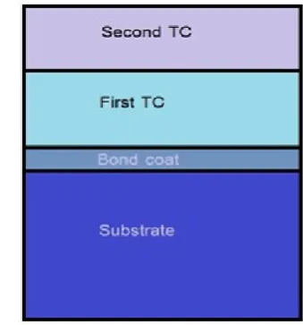
As illustrated graphically in Figure 2. The novel design of functionally graded protective system is assembled of the metallic and ceramic layers with the nominal thickness of 100 mm as following: Inconel 738 metal substrate, NiCoCrAlY metallic bond-coat (BC), 50% BC + 50% YSZ, first ceramic layer of Yttria Stabilized Zirconia (YSZ), 50% YSZ + 50 % LZ and Lanthanum zirconate (LZ) as second ceramic layer on top of all.
Figure 2. Thermal barrier coating with two protective ceramic
Proposed model used in the current research have six layers and is considered as calculation domain for coupled temperature-displacement numerical calculation. In order to construct the model with the maximum accuracy, all interfaces were modeled by a sub-micron asperity (here with wavelength of 30 micro-meter) with sinusoidal interface with specific wavelength. For economical time saving strategy , the domain used for depicting of gathered layer is trim down to almost half of an original sinusidal wavelength.
Three metallurgical postulations were taken into consideration and then were implemented to the ABAQUS commercial finite elemnt code. Perfect bonding between layers was presupposed in all interfaces and also, the presence of porosity in structure was overlooked and at last, no thermal resistance was implemented in the cohesive contact of layers. Not violating the latter limitation, a meshing technique called tie bonding in the software package was implemented. In the method, the connection between nodes of sections in two side of boundary line is remained during thermal loads and mechanical. In other words, a point-to-point coincidental constraint was used for each node at the boundary. Since the effect of temperature is quite influential in material response in high tempaerature, the properties of each individual materials were assigned with temperature dependency mode together with isotropic homogenous material atomic structure.
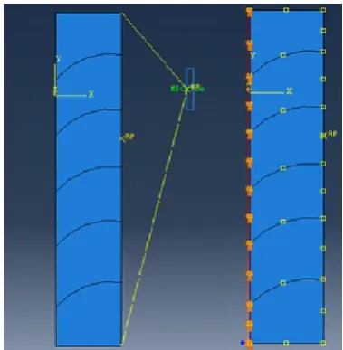
In order to give a real picture and involved condition of configuration, two boundary condition of symmetry and Multi-Point Constraint was utilized and assigned to the left and right edges of coating domain respectively. Multi point constraint allows all nodes of edge to be in simultaneous motion in every horizental direction. Figure 3. indicates the mentioned consideration in the model for establishment of finite element meshing geometry.Element used in this study is two dimensional triangular quadratic six nodes with mechanical plane strain mode and reduced integration. This element selected from library is one of the most efficient element with the ability of calculation and reporting both primary (temperature) and secondary (heat flux) in thermal analysis and displacement iteratively.
To develop and extract the required outputs with the utmost accuracy and confidency in interfaces, this regions as seen in Figure 4. were discretized with quite smaller element size using one-sided biased mesh technique.
Deigned thermal loading cycle during exposing, the thermal cycle on the top-coat surface consists of three stages as illustrated in Figure 5. the heating stage from 25 C to 1400 C in 300 s, followed by a service at 1300 C and finally, a cooling stage from1300C to 25C in 300s. On the other side, convective transfer by the surrounding air is utilized with a coefficient of convection equal to18 W/m2 K.
Figure 3. Symmetrical and periodic multi point boundary
condition used in this study.
Figure 4. Biased mesh generation in the interfaces.
Figure 5. Thermal cycle strategy loaded to the top ceramic
In order to achieve maximum accuracy and consistency in calculation of thermal and mechanical properties of hybrid coating system, all related and required
properties were introduced to the software in temperature- dependent mode as shown in Table 1.
TABLE 1. temperature-dependent data used for simulation [3, 4, 8].
Material T
(K)
E (GPa)
Ρ
(Kg/m3)
α (×10-6×K-1)
ν K
(W/(mk))
Cp (J/Kg.K)
Inconel 276 200 8220 14.4 0.3 11.5 431
673 179 8220 14.4 0.3 17.5 524
1073 149 8220 15.6 0.3 23.8 627
1473 140 8220 15.8 0.3 24.4 712
MCrAlY 276 225 7320 11.6 0.3 4.3 501
673 186 7320 14 0.3 6.4 592
1073 147 7320 16 0.3 10.2 781
1473 134 7320 20.8 0.3 11.3 764
25% BC + 75% YSZ
276 213.75 5880 9.73 0.225 500.25 1.87
673 200.25 5880 11.44 0.225 580 2.2
1073 172.5 5880 12.35 0.225 673 3.04
1473 155 5880 11.58 0.225 678.5 3.29
YSZ 276 210 5400 9.1 0.2 10.6 500
673 205 5400 10.58 0.2 0.8 576
1073 181 5400 11.13 0.2 0.65 673
1473 162 5400 8.5 0.2 0.62 650
3. RESULT AND DISCUSSION
3.1. Optimization of numerical solution In finite element analysis, solving a real engineering case in shorter runtime is more effective and economical due to occurrence of numerical errors as time of solve elongates. Since coupled processes have complex non-linear complicated natures, an exceedingly lengthy time is usually required for achieving solution while no violating convergence criteria. Therefore, some
criterion of accuracy for checking when using such quasi-static tricks and methods like mass scaling. For assuring that the problem is quasi-static, the values of internal and kinetic energy should be checked against each other, the fraction of kinetic energy to internal energy should be kept at approximately less than 5 to 10 percent all over process. For this purpose, history output for both internal and kinetic energy was requested from post-processing module of finite element code and subsequently, combined in one graph and the Figure 6. demonstrates the assessment of this two involved energies with respect to each other. Comparing the internal and kinetic energy shows that in all steps of iterative solution, internal energy is considerably higher than kinetic energy in the graph and kinetic energy is only a small fraction of total consumed energy. Therefore, it can be concluded that, performed analysis can be taken into account as a quasi-static type and proposed mass scaling method reduces solving time without causing numerical calculation error. Moreover, kinetic graph reaches its peak at the middle of the process; that is to say, the point which consumed energy at these times was used for accelerating the process.
Figure 6. Evaluation of kinetic and internal energy for
quasi-static criteria.
During high values of distortion especially in interfaces with small meshing region, strain values are induced into the materials during thermal stress, which can cause the solution procedure to stop after a specific deformation attempt. For tackling this problem with considering material specific nature, hybrid adaptive meshing is introduced as a proficient and helpful technique to keep the element away from excessive distortion and prohibition of element mass to approach zero, which causes divergence and incomplete solution. In this approach, the movements of element nodes become independent of geometry deformation; therefore, the quality and dimensions of elements remains in fine and acceptable situation. In other words, when strain is induced to the model, only the node coordinates of elements alters and the geometry and topological feature of elements experience no change. Efficient avoidance from excessive distortion, a significant and proper frequency and sweeping factor
have to be considered while implementing adaptively to elements imposed to large destructive elements. The former identifies the number of increments. After what, re-meshing takes place and the later parameter gives the number of orientation change in each re-meshing effort. A set of (10, 3) was decided to be used for frequency and sweep factor, respectively for analysis in this study.
3.2. Stress distribution in sub-micron interface of coating Prior to focal analysis, mesh sensitivity analysis is essential to guarantee that extracted results are independent of mesh size and element design and arrangement. Relatively unnecessary small element size leads to unnecessary increase in solving time and consequently in numerical errors and on the counter. Since large meshing strategy causes some error in problem solving accuracy, an edge of coating with maximum temperature variation was preferred for this intention and a range of element number (here interpreted as element size) was tested and finally, the most favorable mesh size was selected. The optimum size can be interpreted as follow: the smallest mesh size, in which the trend of a specific parameter (temperature in this study) in graph starts to become plateau. Figure 7. shows the variation of temperature with element size in this research which gives a proper sensitivity analysis.
As can be seen in the Figure 8. in all duration of thermal load to the double layer ceramic functionally graded thermal barrier coating, concentration of heat is located in the upper section of the coating system and this means that, all lower metallic part mainly Inconel substrate are inaccessible from thermal damages. In other words, make use of this coating; heat transfer is limited to the heat resistive ceramic sections of coating and bond coat and substrate experience lower temperatures. Hence, higher working temperatures can be experienced especially in aerospace turbine applications.
Figure 7. Mesh sensitivity examination for coating thermo-
Figure 8. Temperature distribution in TBC in (a) t = 150 s (b) t = 175 s (c) t = 200 s (d) t = 225 s.
Having protected the substrate from thermal load and keeping in relatively lower temperatures lead to superior fatigue life and also, increasing lifetime and decreasing protection cost. Figure 9. shows the heat flux dissipation in thermal barrier coating assembled in functionally graded mode. Just like the temperature distribution, the co-existences of double ceramic layer keeps thermal load and thermal energy on itself and as a consequence, thermal equilibrium of upper hot parts with hot outside air is achieved in a shorter time period. The equilibrium between ceramic coats and outer air avoids thermal diffusion to the bond coat and more importantly, nickel-base substrate. As a definition, a thermal barrier was established when thermal equilibrium was gained in the two ceramic layers on the top of coating and this have good effects on maximum temperature. The trend and pattern of temperature among different layers is in agreement with the contours given off by Ranjbar et al [3]. In other word, the ceramic layer with relatively low thermal conductivity just at the upper surface of the protective layer is the main agent in keeping the coating out of oxidation and degradation damage at high temperatures [4, 7].
Figure 10. and 11. illustrate the stress distribution contours in TBC arrangement after cooling step
considering sinusoidal interface of MCrAlY / 50% MCrAlY + 50% YSZ .
Figure 9. Heat flux in TBC in (a) t = 150 s (b) t = 175 s (c) t =
200 s (d) t = 225 s.
Figure 10. Stress in sinusoidal interface of MCrAlY/ YSZ.
Because of higher value of thermal expansion in bond coat with respect to ceramic layer, compressive strength was induced in peak regions and tensile strength in valley of sub-micron interface and a slow transition was seen while approaching from peak to valley which was first suggested by Chen while facing multi-cycle thermal shock with and without external loading [14].This sub-micron profile in the transition band between metallic and ceramic materials causes some heterogeneity in stress field distribution and gives relatively more potent stress concentration zones comparing with typical flat surfaces. In FGM coating, LZ materials present in YSZ improve the metallurgical flaws of this layer and likewise, YSZ component in MCrAlY Hence; it causes a better isolation function and less downward thermal diffusion.
Figure 11. Stress distribution in (a) FG -TBC (b) conventional TBC.
As an outstanding point in FGM strategy, it can be mentioned that, the maximum stress in the structure is approximately half of those in conventional TBC systems therefore; it can be suggested as a new design of high temperature material. Comparison of distortion in both conventional and FGM coating is illustrated in Figure 12. and the trend can be seen like stress variation and FGM bear less destructive elongation.
Figure 12. Comparison of distortion in both conventional and
FGM coating.
4. DATA COLLECTION AND MODEL VALIDAION
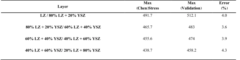
Like any numerical approaches to physical phenomena in materials and because there was no experimental phase in the project, a research method with both experiment and simulation dimension was selected. Physical data and essential consideration were utilized and finite element model was established. Acceptable agreement was seen in the comparison of their results and this simulation. Table 2 illustrates this fact.
TABLE 2. Validation of model with the work of chen t al [1]
Layer (ChenMax)Stress (ValidationMax ) Error(%)
LZ / 80% LZ + 20% YSZ 491.7 512.1 4.0
80% LZ + 20% YSZ/ 60% LZ + 40% YSZ 465.7 483 3.6
60% LZ + 40% YSZ/ 40% LZ + 60% YSZ 455.6 474 3.9
40% LZ + 60% YSZ/ 20% LZ + 80% YSZ 438.7 458.2 4.3
5. CONCLUSION
Based on the preceding discussion the following concluding remarks can be drawn:
The thermal and residual stress distribution in a novel three layer (La2Zr2O7/ 8YSZ/ NiCrAlY) during a
real-like heating regime was studied. Results revealed that most of the damage and harmful thermal load and residual stress concentrate on ceramic top coats. FGM strategy reduced the stress values in the coating to half of its value in conventional coating. Small difference in thermal expansion improves the adhesive bonding between different ceramic/ ceramic and ceramic / metal interfaces with sub-micron asperity and also decreases the risk for crack initiation and propagation. The Mass scaling method reduces the running time while satisfying convergence and accuracy criteria and the
efficiency of this method was tested by comparing internal and kinetic energy during process.
Appendix 1:
The governing mathematical equations related to simulation are as follow:
= + + + Q
= ( ) (| |{ } ) +
= { } ([ ]{ } ) + + ℎ ( − )
+ ({ } ([ ]{ } ))
( [ ] [ ] { }) + ([ ] [ ][ ]{ })
= [ ] + [ ] ℎ ( − [ ] { })
= ( + ) + ∇ − (3 + 2 ) +
=
REFERENCES
1. Vaßen, R., Ophelia Jarligo, M., Steinke, T., Emil Mack, D. and Stöver, D., "Overview on advanced thermal barrier coatings",
Surface and Coatings Technology, Vol. 205, No. 4, (2010), 938-942.
2. Wang, L., Wang Y., Zhang, W.Q., Sun, X.G., He, J.Q., Pan, Z.Y. and Wang, C.H., "Finite element simulation of stress distribution and development in 8YSZ and double-ceramic-layer La2Zr2O7/8YSZ thermal barrier coatings during thermal shock", Applied Surface Science, Vol. 258, (2012), 3540-3551. 3. Naga, S.M., "21 – Ceramic matrix composite thermal barrier
coatings for turbine parts", Advanced in Ceramic Matrix Composites, Vol. 3, (2014), 524-536.
4. Ranjbar-far, M., Absi, J., Mariaux, G. and Smith, D.S., "Crack propagation modeling on the interfaces of thermal barrier coating system with different thickness of the oxide layer and different interface morphologies", Materials and Design,
Vol.32, No. 10, (2011), 4961-4969.
5. Ranjbar-Far, M., Absi, J., Shahidi, S. and Mariaux, G., " Impact of the non-homogenous temperature distribution and the coatings process modeling on the thermal barrier coatings system", Materials and Design, Vol. 32, No. 2, (2011), 728-735.
6. Białas, M., " Finite element analysis of stress distribution in thermal barrier coatings", Surface and Coating Technology,
Vol. 202, (2008), 6002–6010.
7. Bengtsson, P. and Persson, C., "Modeled and measured residual stresses in plasma sprayed thermal barrier coatings", Surface and coating technology, Vol. 92, (1997), 78-86.
8. Ranjbar-Far, M., Absi, J., Mariaux, G. and Dubois, F., "Simulation of the effect of material properties and interface roughness on the stress distribution in thermal barrier coatings using finite element method", Materials and Design, Vol. 31, (2010), 772-781.
9. Widjaja, S., Limarga, A.M. and Hon Yip, T., "Modeling of residual stresses in a plasma-sprayed zirconia/alumina functionally graded-thermal barrier coating", Thin Solid Films,
Vol. 434, (2003), 216-227.
10. Widjaja, S., Limarga, A.M. and Hon Yip, T., "Oxidation behavior of a plasma-sprayed functionally graded ZrO2/Al2O3 thermal barrier coating", Materials Letters, Vol. 57, (2002), 627-634.
11. obczak, J. and Ludmil Drenchev, J., "Metallic Functionally Graded Materials: A Specific Class of Advanced Composites",
Journal of Materials Science and Technology, Vol. 29, No. 4, (2013), 297-316.
12. Kieback, B., Neubrand, A. and Riedel, H., "Processing techniques for functionally graded materials", Materials Science and Engineering, Vol. 362, (2003), 81–105.
13. Saeedi, B., Sabour, A., Ebadi, A. and Khoddami, A.M., "Influence of the Thermal Barrier Coatings Design on the Oxidation Behavior", Journal of Materials Science and Technology, Vol. 25, No. 4, (2009), 499-507.
14. Chen, X., Gu, L., Zou, B., Wang, Y. and Cao, X., "New functionally graded thermal barrier coating system based on LaMgAl11O19/YSZ prepared by air plasma spraying", Surface and Coatings Technology, vol. 206, (2012), 2265–2274. 15. Wang, L., Wang, Y., Sun, X.G., He, J.Q., Pan, Z.Y. and Wang,
C.H., "A novel structure design towards extremely low thermal conductivity for thermal barrier coatings – Experimental and mathematical study", Materials and design, Vol. 35, (2012), 505-517.
16. Wang, L., Wang, Y., Sun, X.G., He, J.Q., Pan, Z.Y. and Wang, C.H., " Finite element simulation of residual stress of double-ceramic-layer La2Zr2O7/8YSZ thermal barrier coatings using birth and death element technique", Computational Materials Science, Vol. 53, (2012), 117–127.
17. Han, M., Zhou, G., Huang, J. and Chen, S.H., "A parametric study of the double-ceramic-layer thermal barrier coatings part I: Optimization design of the ceramic layer thickness ratio based on the finite element analysis of thermal insulation (take LZ 7 C 3/8YSZ/NiCoAlY DCL-TBC for an example)", Surface and Coatings Technology, Vol. 236, (2013), 500-509.
18. Han, M., Zhou, G., Huang, J. and Chen, S., "Optimization selection of the thermal conductivity of the top ceramic layer in the Double-Ceramic-Layer Thermal Barrier Coatings based on the finite element analysis of thermal insulation", Surface and Coatings Technology, Vol. 240, (2014), 320–326.
19. Han, M., Huang, J. and Chen, S., "A parametric study of the Double-Ceramic-Layer Thermal Barrier Coating Part II: Optimization selection of mechanical parameters of the inside ceramic layer based on the effect on the stress distribution",
Surface and Coatings Technology, Vol. 238, (2014), 93-117. 20. Han, M., Huang, J. and Chen, S., "Behavior and mechanism of
![TABLE 1. temperature-dependent data used for simulation [3, 4, 8].](https://thumb-us.123doks.com/thumbv2/123dok_us/8894538.1827092/4.595.54.530.163.629/table-temperature-dependent-data-used-for-simulation.webp)