1
*Corresponding author: [email protected] 71
Simultaneous High Hydrogen Content-Synthesis Gas Production
and In-Situ CO
2Removal via Sorption-Enhanced Reaction Process:
Modeling, Sensitivity Analysis and Multi-objective Optimization
using NSGA-II Algorithm
M. Heravi1, M. Bayat2*, M. R. Rahimpour1
1Department of Chemical Engineering, School of Chemical and Petroleum Engineering,
Shiraz University, Shiraz 71345, Iran
2Department of Chemical Engineering, Faculty of Engineering, University of Bojnord, Bojnord, Iran
ARTICLE INFO ABSTRACT
Article history: Received: 2016-03-10
Accepted: 2016-04-18
The main focus of this study is improvement of the steam-methane reforming (SMR) process by in-situ CO2 removal to produce high
hydrogen content synthesis gas. Sorption-enhanced (SE) concept is applied to improve process performance. In the proposed structure, the solid phase CO2 adsorbents and pre-reformed gas stream are
introduced to a gas-flowing solids-fixed bed reactor (GFSFBR). One dimensional mathematical model is developed to evaluate the effect of adsorbents on the efficiency of SMR at steady-state condition. To prove the accuracy of the considered model, simulation results are compared against available industrial plant data. Modeling results illustrate that application of SE method in SMR enhances syngas production and reduces CO2 content. The reported data indicate that by overcoming
thermodynamic limitations and controlling coke formation, CH4
conversion and H2 yield improve about 23 % and 29 %, respectively.
For more investigation, sensitivity analyses of some related parameters of the pre-reformed gas are performed to predict optimum conditions. Finally, the proposed GFSFBR for the SMR process leads to higher hydrogen production and H2/CO ratio. As the last part, non-dominated
sorting genetic algorithm-II is applied to perform multi-objective optimization of the SE-SMR.
Keywords:
Hydrogen Production Steam-Methane Reforming Sorption-Enhanced Reaction
CO2 Adsorption
Multi-objective Optimization
1. Introduction
Due to the increase in energy demands and the depletion of natural resources, searching for alternative energy sources has recently
72 Iranian Journal of Chemical Engineering, Vol. 13, No. 4 (Autumn 2016) (SMR) [1]. This process, which includes the
reaction of methane with steam, particularly in the presence of Ni/Al2O3 catalyst, occurs at
the temperature and pressure range of 400– 900 ◦C and 1–30 atm, respectively [2]. Several researchers have studied SMR process from different viewpoints. The studies often include enhancement of H2 production [3-5].
More important than finding a renewable and non-carbon based energy resource is controlling emissions of greenhouse gases, especially CO2. This crisis has motivated
scientists to find effective methods for CO2
removal. One of the cost-effective and energy-efficient techniques is CO2 adsorption in the
reactor media called sorption-enhanced reaction (SER) [6]. SER is an effective concept which alleviates thermodynamic limitations of the equilibrium reactions by selectively removing some of the reaction products from the reaction zone, thereby shifting the equilibrium towards higher production and conversion (according to Le Chatelier’s principle) [6]. Eliminating the equilibrium limitations of the reactions would considerably reduce the relevant expenses for the separation of non-converted reactants from the products [7]. As a description on earlier works, Westerterp and Kuczynski studied methanol synthesis in a gas-solid-solid trickle bed reactor [7]. They observed conversion increase when methanol adsorbents were added to the system and found reduction of costs and energy consumption in the process. Ding and Alpay investigated the SE-SMR at high temperature both experimentally and theoretically in the presence of CO2
adsorbents [8]. From their results, it appears
that introducing CO2 adsorbents enhances the
process with higher methane conversion. In 2011, SER in steam reforming of ethanol was studied for hydrogen production, and significant increase in hydrogen yield was reported in the presence of appropriate CO2
adsorbent [9]. However, there are some drawbacks of in-situ CO2 sorption: the limited
capacity of the adsorbent particles, influence of high temperature condition on the adsorbents, and the necessity of continuous and easy regeneration of adsorbents. In this paper, K2CO3-promoted hydrotalcite
chemi-sorbents are used in a gas-flowing solids-fixed bed reactor (GFSFBR). The adsorbents offer nearly infinite selectivity for adsorbing CO2.
Recently, our research team has published several papers on the concept of SER by H2O
removal occurring in the GFSFBR for methanol synthesis [10-12]. To the best of our knowledge, this is the first effort in which the SE-SMR process is mentioned in a GFSFBR system in the presence of K2CO3-promoted
hydrotalcite, and three objective functions are optimized simultaneously. In the GFSFBRs, a solid phase (fine adsorbent particles) and a gas phase are introduced to the packed bed reactors in which catalyst particles are placed, flowing together into the reaction medium in co-current (or counter-current) mode [13]. Because of the GFSFBRs’ adsorbents regenerability, which is the main preeminence of these types of reactors over the conventional ones, a regenerator is embedded beside the reactor.
2. Objectives
Iranian Journal of Chemical Engineering, Vol. 13, No. 4 (Autumn 2016) 73 concept is applied to promote SMR process in
order to produce higher-purity hydrogen and reduce carbon dioxide emission by introducing CO2 adsorbents to the system
co-currently. A steady state two-phase theory in plug flow regime is developed to analyze the performance of the new configuration of the industrial steam reformer reactor in the presence of the K2CO3-promoted hydrotalcite
as CO2 adsorbent. Finally, in order to
investigate the superiority of GFSFBR over CR, the results of both reactor configurations are compared. Meanwhile, the operating conditions of GFSFBR configuration are optimized via the multi-objective optimization method to maximize three object functions of CH4 conversions, CO selectivity and H2/CO
ratio.
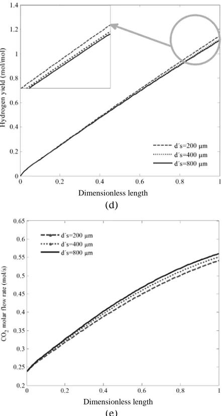
3. Process description 3.1. Conventional SMR
Figure 1 indicates a simplified schematic diagram of a steam reforming unit that is principally composed of a reformer and a reactor [14]. The conventional reformer, which was comprised of a hot opening with huge furnace, contains 184 tubes in 4 rows to decrease heat loss and the number of flambeaus. Heat is transferred to the whole length of tubes. In most cases, commercial Ni/Al2O3 catalysts, which are vertically
packed in tubes, are exposed to reactions medium. The fired furnace supplies the required energy of the system and the heat produced in combustion is transferred to the endothermic steam reforming reactions through furnace flambeaus to produce
74 Iranian Journal of Chemical Engineering, Vol. 13, No. 4 (Autumn 2016) synthesis gas. As seen, natural gas is first
mixed with steam before the gaseous feed enters the tubes of steam reformer and then the SMR reactions are carried out while passing through the fixed bed of catalytic particles in order to produce the final product of syngas. The outlet stream has a relatively high value of H2/CO ratio that must be
adjusted to the optimum value proper for efficient synthesis of methanol. To this end, an autothermal reactor is located downstream of the reformer.
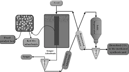
3.2. Proposed structure
In the understudied reactor of the current work, adsorbents, as an additional mobile phase accompanied by gas phase, are fed to the system, flowing along the length of the reactor to reduce CO2 content of the reaction
medium by adsorption mechanism. A schematic of this type of reactor is shown in Fig. 2.
Both the prereformed gas and adsorbents enter the reactor, simultaneously, in order to eliminate thermodynamic limitations of the chemical reactions which are taking over the conventional catalysts through a sorption-enhanced reaction. As mentioned before, adsorbents are regenerated at the end of each adsorption cycle and become fresh in the regenerator so as to be utilized in the next process cycle, introduced at the entrance of the GFSFBR. Continuous regeneration can be enforced applying a proper regeneration technology [15]. Desorbed CO2 is sent to the
methanol synthesis unit. The specifications of the reformer, catalyst and feed composition are available in the literature [16].
Iranian Journal of Chemical Engineering, Vol. 13, No. 4 (Autumn 2016) 75 4. Reaction scheme and kinetic expression
In this effort, three main reactions considered as the reaction network in steam reformer reactor are presented in Table 1 [17].
The first and the second reactions (1 and 2) are called steam-methane reforming (SMR) reactions through which methane and steam are consumed. The main products of the reaction network are syngas (mixture of CO and H2) and CO2. SMR reactions are highly
endothermic while the third reaction is slightly exothermic, namely water–gas shift (WGS) reaction. Considering the two endothermic reactions, it is necessary to performed SMR process at high temperatures, which consequently brings about complete methane conversion [16].
Offering a set of approved rate equations is essential to start a mathematical modeling with absolute certainty. Therefore, Xu and Froment model over Ni-based catalyst is applied in this work for predicting the rate of the abovementioned reactions [15]. Arrhenius kinetic parameters, reaction equilibrium constants, and Van’t Hoff parameters for adsorption of species are available [16].
5. Mathematical modeling
In this study, a one-dimensional heterogeneous model is developed to investigate the performance of the proposed structure at steady-state condition. The considered assumptions in the developed
model are as follows:
•Plug flow pattern is assumed for both gas and flowing solids phases.
•Axial diffusion of heat and mass is negligible as compared with convection.
•Bed void fraction in radial directions is considered to be constant.
•The gas phase is considered to be ideal.
•The total molar flow rate is determined, so as to vary along the reaction pathway.
•Heat loss is negligible.
Based upon the aforementioned assumptions, both mass conservation law and first law of thermodynamics for energy balance were applied over a specified differential element. When time variations of the states are set to zero, the mass and energy balance equations for the bulk gas phase (1 & 2) and the catalyst pellets (3 & 4) are:
−𝐴𝐴1
𝑐𝑐
𝑑𝑑𝐹𝐹𝑖𝑖
𝑑𝑑𝑑𝑑 +𝑎𝑎𝑠𝑠.𝑐𝑐𝑡𝑡.𝑘𝑘𝑔𝑔𝑖𝑖(𝑦𝑦𝑖𝑖𝑠𝑠− 𝑦𝑦𝑖𝑖)
−𝛾𝛾.𝑘𝑘′𝑔𝑔.𝑎𝑎′𝑠𝑠.𝜌𝜌′𝑠𝑠�𝑞𝑞𝐶𝐶𝑂𝑂∗ 2− 𝑞𝑞𝐶𝐶𝑂𝑂2�= 0
𝑖𝑖= 1,2, . . . ,6 (1)
−𝐴𝐴1
𝑐𝑐𝐶𝐶𝑝𝑝𝑔𝑔
𝑑𝑑(𝐹𝐹𝑡𝑡𝑇𝑇)
𝑑𝑑𝑑𝑑 +𝑎𝑎𝑠𝑠ℎ𝑓𝑓(𝑇𝑇𝑠𝑠− 𝑇𝑇)
−ℎ′𝑓𝑓𝑎𝑎′𝑠𝑠(𝑇𝑇 − 𝑇𝑇′𝑠𝑠) +𝑄𝑄= 0 (2) 𝑎𝑎𝑠𝑠.𝑐𝑐𝑡𝑡.𝑘𝑘𝑔𝑔𝑖𝑖(𝑦𝑦𝑖𝑖− 𝑦𝑦𝑖𝑖𝑠𝑠) +𝜌𝜌𝐵𝐵.𝜂𝜂𝑖𝑖.𝑟𝑟𝑖𝑖 = 0
𝑖𝑖= 1,2, . . . ,6 (3)
𝑎𝑎𝑠𝑠.ℎ𝑓𝑓. (𝑇𝑇 − 𝑇𝑇𝑠𝑠) +𝜌𝜌𝐵𝐵� 3
𝑗𝑗=1𝜂𝜂𝑗𝑗𝑅𝑅𝑗𝑗. (−Δ𝐻𝐻𝑓𝑓,𝑖𝑖)
= 0 (4)
Required boundary conditions are: yi=yi0 and
0 T
T= at z=0.
Table 1
Three main reactions in SMR [17].
Equation number Equilibrium reactions Standard enthalpy 1
2 2
4 H O CO 3H
CH + ↔ + 1
298 206.3
−
=
∆H kJmol
2 CH4+2H2O↔CO2+4H2 1
298 164.9
−
=
∆H kJmol
3
2 2
2O CO H
H
CO+ ↔ + 1
298 41.1
−
− =
76 Iranian Journal of Chemical Engineering, Vol. 13, No. 4 (Autumn 2016) The effectiveness factor (ηj) can be found in
Gosiewski et al.’s paper [18], where Q is the supplied heat by the reformer furnace. It is noticeable that the value of γ is considered to be unity for CO2 component and zero for
others.
Presenting material and energy balance criteria in this section is completed by considering equations related to the flowing solids as the third phase, over a differential volume. Regarding the fact that the concentration of adsorbed CO2 is increasing
along the reactor, the following equations are added to the developed model:
𝑢𝑢′𝑠𝑠𝑑𝑑𝑞𝑞𝑑𝑑𝑑𝑑 = 𝑘𝑘′𝑔𝑔𝑎𝑎′𝑠𝑠�𝑞𝑞𝐶𝐶𝑂𝑂∗ 2− 𝑞𝑞𝐶𝐶𝑂𝑂2� (5)
𝑢𝑢′𝑠𝑠𝜌𝜌′𝑠𝑠𝐶𝐶𝑝𝑝′𝑠𝑠𝑑𝑑𝑇𝑇′𝑑𝑑𝑑𝑑𝑠𝑠 =−Δ𝐻𝐻𝑎𝑎𝑎𝑎𝑠𝑠𝑆𝑆𝑎𝑎′𝑠𝑠�𝑞𝑞𝐶𝐶𝑂𝑂∗ 2 − 𝑞𝑞𝐶𝐶𝑂𝑂2� +ℎ′𝑓𝑓𝑎𝑎′𝑠𝑠(𝑇𝑇 − 𝑇𝑇′𝑠𝑠) (6)
In the above equations,
2 CO
q , describes the concentration of CO2 in the flowing solids. kg′, which denotes the mass transfer coefficient between gas phase and the adsorbents, is estimated by the Ranz-Marshall correlation [19]. More importantly, *
2 CO
q term that describes the adsorption/desorption isotherm of CO2 on K2CO3 particles is calculated by the
following Langmuir isotherm:
𝑞𝑞𝐶𝐶𝑂𝑂2∗ = 𝑚𝑚1 +𝐶𝐶𝑂𝑂2𝑏𝑏𝑏𝑏𝐶𝐶𝑂𝑂2𝑃𝑃𝐶𝐶𝑂𝑂2 𝐶𝐶𝑂𝑂2𝑃𝑃𝐶𝐶𝑂𝑂2
(7)
The required parameters for the Eqs. (1-7) are available in the literature [8,15,16].
Another differential equation of this section is associated with the pressure drop along the reactor. Several articles have been extensively discussed on the pressure drop and flowing solids hold up of the well-known gas-flowing
solids-fixed bed contactors [20-22] due to the fact that the total pressure greatly affects the concentration of reactants in gas-phase reactions. In summary, two main reasons which cause pressure drop in this type of reactor are widely investigated in the literature [23]. The correlation of the pressure drop along the length of GFSFBRs is formulated as follows:
𝑑𝑑𝑝𝑝 𝑑𝑑𝑑𝑑 =− �
150
𝑅𝑅𝑒𝑒𝑠𝑠 + 1.75�
𝑢𝑢𝑔𝑔2𝜌𝜌𝑔𝑔
𝑑𝑑𝑒𝑒𝑒𝑒
(1− 𝜀𝜀′)
𝜀𝜀′3
−34𝐶𝐶𝑎𝑎𝛽𝛽𝑑𝑑′𝑎𝑎𝜌𝜌𝑔𝑔𝑢𝑢𝑟𝑟2
𝑠𝑠𝜀𝜀′
(8)
Due to the presence of flowing particles, void fraction of the packed bed is corrected which is assigned by ε´. For more explanation of the terms
β
d (dynamic holdup),β
, andβ
s(static holdup) references are presented [23,24]. The following empirical correlations are commonly used to calculate the dynamic and static holdup [23].
𝛽𝛽𝑎𝑎 = 9.67. Ré𝑠𝑠1.123.𝐴𝐴𝑟𝑟−0.486� 𝑆𝑆 2
𝜌𝜌′
𝑠𝑠.𝜌𝜌𝑔𝑔.𝑢𝑢𝑔𝑔2� −453
.�𝑑𝑑𝑑𝑑𝑒𝑒𝑒𝑒
𝑠𝑠 ′ �
−0.647
.𝜀𝜀−0.404(1− 𝜀𝜀)0.726 (9)
𝛽𝛽𝑠𝑠 = 0.0295.𝛽𝛽𝑎𝑎0.214.�𝑑𝑑𝑑𝑑𝑒𝑒𝑒𝑒′ 𝑠𝑠�
−1.82
.𝜙𝜙−2.69
.𝜀𝜀−0.31(1− 𝜀𝜀)1.61 (10)
Other parameters of the equation can be simply calculated by the auxiliary correlations.
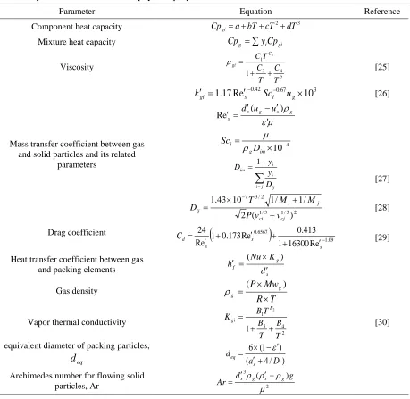
6. Auxiliary correlations and numerical solution
Iranian Journal of Chemical Engineering, Vol. 13, No. 4 (Autumn 2016) 77 coupled with the auxiliary correlations.
Required correlations are presented in Table 2. Molecular weight and critical volume of the components can be obtained from the literature [31].
In order to achieve concentration, pressure, and temperature profiles along the reactor, the set of ordinary differential equations plus algebraic equations are solved by backward finite difference approximation on a
discretized domain, applying Gauss–Newton method.
7. Optimization
In the present work, multi-objective optimization method is applied in order to maximize CH4 conversion, CO selectivity, and
H2/CO ratio simultaneously. The reason why
multi-objective optimization is selected refers to the cost of feed, the cost of the additional
Table 2
Auxiliary correlations to estimate physical properties, mass and heat transfer coefficients.
Parameter Equation Reference
Component heat capacity Cpgi=a+bT+cT2+dT3
Mixture heat capacity Cpg =∑yiCpgi
Viscosity 2 4 3 1 1 2 T C T C T C C gi + + = µ [25]
Mass transfer coefficient between gas and solid particles and its related
parameters 3 67 . 0 42 . 0 10 e R 17 .
1 ′ ×
=
′ − −
g i s
gi Sc u
k [26] µ ε ρ ′ ′ − ′ =
′ s g s g
s
u u d ( ) e R 4 10− × = im g i D Sc ρ µ
∑
= − = j i ij i i im D y y D 1 [27] 2 3 / 1 3 / 1 2 / 3 7 ) ( 2 / 1 / 1 10 43 . 1 cj ci j i ij v v P M M T D + + × = − [28]Drag coefficient
(
)
09 . 1 6567 . 0 e R 16300 1 413 . 0 e R 173 . 0 1 e R 24 − ′ + + ′ + ′ = s s s d C [29]
Heat transfer coefficient between gas and packing elements
s g f d K Nu h ′ × = ′ ( ) Gas density T R Mw P g g × × =( ) ρ
Vapor thermal conductivity
2 4 3 1 1 2 T B T B T B K B gi + + = [30]
equivalent diameter of packing particles,
eq
d ( 4/ )
) 1 ( 6 i s eq D a d + ′ ′ − × = ε
Archimedes number for flowing solid
particles, Ar 2
3 ) ( µ ρ ρ ρ g d
78 Iranian Journal of Chemical Engineering, Vol. 13, No. 4 (Autumn 2016) furnace fuel, and hydrogen-rich synthesis gas
production as a great source of energy [32].
7.1. Multi-objective optimization
Multi-objective optimization (MO) contributes to a set of non-dominated solutions named as a Pareto optimal set [33]. Any solution of this set cannot be regarded as a better or worse solution than the others. A curve called Pareto optimal front connects all points of the Pareto set, in that any point along this curve can be improved if there is a fall-off in at least one of the other objectives.
Among different methodologies for solving MO problems, evolutionary algorithms (EAs) which have become of immense interest for the simple reason of being able to find multiple Pareto optimal solutions, are used in this study [34]. One of the most efficient and famous EAs is non-dominated sorting genetic algorithm-II (NSGA-II) which is characterized by its acceptable convergence of the non-dominated front and appropriate dispersion of solutions [10]. A flowchart of NSGA-II and a brief description of the steps involved in this algorithm can be found in the previous publications [10, 35]. In order to optimize the proposed reactor, four case studies are checked using NSGA-II algorithm and MATLAB programming. Essential information about the parameters of NSGA-II algorithm for case studies is presented in Table 3.
7.2. First case study
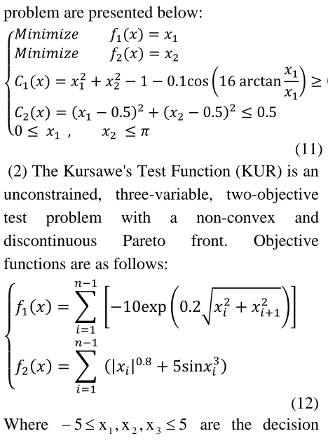
In the first case study, working of NSGA-II algorithm was evaluated using two difficult test problems. (1) The Tanaka Test Function
(TNK) is a constrained, variable, two-objective test problem with discontinuous Pareto front. Objective functions of this test problem are presented below:
⎩ ⎪ ⎨ ⎪
⎧𝑀𝑀𝑖𝑖𝑀𝑀𝑖𝑖𝑚𝑚𝑖𝑖𝑑𝑑𝑒𝑒𝑀𝑀𝑖𝑖𝑀𝑀𝑖𝑖𝑚𝑚𝑖𝑖𝑑𝑑𝑒𝑒 𝑓𝑓𝑓𝑓1(𝑥𝑥) =𝑥𝑥1 2(𝑥𝑥) =𝑥𝑥2
𝐶𝐶1(𝑥𝑥) =𝑥𝑥12+𝑥𝑥22−1−0.1cos�16 arctan𝑥𝑥𝑥𝑥1 1� ≥0 𝐶𝐶2(𝑥𝑥) = (𝑥𝑥1−0.5)2+ (𝑥𝑥2−0.5)2≤0.5
0≤ 𝑥𝑥1 , 𝑥𝑥2 ≤ 𝜋𝜋
(11) (2) The Kursawe's Test Function (KUR) is an unconstrained, three-variable, two-objective test problem with a non-convex and discontinuous Pareto front. Objective functions are as follows:
⎩ ⎪ ⎨ ⎪
⎧𝑓𝑓1(𝑥𝑥) =� 𝑛𝑛−1
𝑖𝑖=1
�−10exp�0.2�𝑥𝑥𝑖𝑖2+𝑥𝑥𝑖𝑖+12 ��
𝑓𝑓2(𝑥𝑥) =� 𝑛𝑛−1
𝑖𝑖=1
(|𝑥𝑥𝑖𝑖|0.8+ 5sin𝑥𝑥𝑖𝑖3)
(12) Where −5≤x1,x2,x3 ≤5 are the decision
variables.
7.3. Second case study
Seven decision variables are chosen in this optimization: inlet temperature of both gas and flowing solid phases, mass flux and diameter of the adsorbents, pressure, total molar flow rate, and H2/CH4 ratio. Each of
these variables has specific constraints presented below:
773 < 𝑇𝑇𝑔𝑔 < 923 (𝐾𝐾) (13)
773 < 𝑇𝑇𝑠𝑠′< 923 (𝐾𝐾) (14)
10−5 <𝑆𝑆< 10−3 ( 𝑘𝑘𝑘𝑘
𝑚𝑚2.𝑠𝑠) (15)
200 < 𝑑𝑑𝑠𝑠 < 1000 (𝜇𝜇𝑚𝑚) (16)
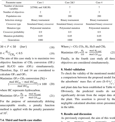
Iranian Journal of Chemical Engineering, Vol. 13, No. 4 (Autumn 2016) 79 Table 3
Applied parameters in NSGA-II algorithm for case studies.
Parameter name Case 1 Case 2&3 Case 4
Number of decision
variables 2(TNK) and 3(KUR) 7 7
Number of objectives 2 2 3
Population size 500 200 200
Selection strategy Binary tournament Binary tournament Binary tournament
Crossover type Simulated binary crossover Simulated binary crossover Simulated binary crossover
Mutation type Polynomial mutation Polynomial mutation Polynomial mutation
Crossover probability 0.9 0.9 0.9
Mutation probability 0.05 0.05 0.05
Generations 1000 1000 1000
30 <𝑃𝑃< 50 (𝑏𝑏𝑎𝑎𝑟𝑟) (18)
0 < 𝐻𝐻2
𝐶𝐶𝐻𝐻4
� < 0.5 (19)
The aim of this case study is to maximize two objective functions of CH4 conversion (OF1)
and H2/CO ratio (OF3) simultaneously.
Therefore, Eqs. 13 and 14 are considered to calculate OF1 and OF3.
Maximize: OF1= CH4 conversion (%) =
(𝑚𝑚𝑚𝑚𝑚𝑚𝐻𝐻𝐶𝐶𝑚𝑚𝑚𝑚𝑚𝑚𝑖𝑖𝑛𝑛− 𝑚𝑚𝑚𝑚𝑚𝑚𝐻𝐻𝐶𝐶 𝐻𝐻𝐶𝐶𝑜𝑜𝑜𝑜𝑡𝑡
𝑖𝑖𝑛𝑛 ) × 100 (20)
where HC represents hydrocarbon.
Maximize: OF3= 𝐻𝐻2
𝐶𝐶𝑂𝑂
=
𝑚𝑚𝑜𝑜𝑚𝑚𝐻𝐻2𝑜𝑜𝑜𝑜𝑜𝑜
𝑚𝑚𝑜𝑜𝑚𝑚𝐶𝐶𝑂𝑂𝑜𝑜𝑜𝑜𝑜𝑜 (21)
For the purpose of automatically deleting unacceptable results, a penalty function method is applied with the penalty parameter of 107.
7.4. Third and fourth case studies
According to the second case, simultaneous maximization of CO selectivity (OF2) and
H2/CO ratio (OF3) is performed in the third
case study. Related equations are as follows:
Maximize: OF2 = CO selectivity (%) =
(Σ𝑚𝑚𝑚𝑚𝑚𝑚𝑚𝑚𝑚𝑚𝑚𝑚𝑚𝑚𝑓𝑓𝐶𝐶𝑜𝑜𝑜𝑜𝑡𝑡𝑗𝑗
𝑜𝑜𝑜𝑜𝑡𝑡) × 100 (22)
Where j = CO, CO2, H2, H2O and CH4
Maximize: OF3 =𝐻𝐻2
𝐶𝐶𝑂𝑂
=
𝑚𝑚𝑜𝑜𝑚𝑚𝐻𝐻2𝑜𝑜𝑜𝑜𝑜𝑜
𝑚𝑚𝑜𝑜𝑚𝑚𝐶𝐶𝑂𝑂𝑜𝑜𝑜𝑜𝑜𝑜 (23)
Finally, in the fourth case study all three objectives are considered simultaneously.
8. Model validation
To check the validity of the mentioned model, a comparison between the proposed model for the adsorbents’ mass flux of zero (S=0
s m kg
.
2 )
and plant data has been established in Table 4. Obviously, the predicted results do not significantly deviate from the output data of the plant. This assertion is proved by the negligible calculated absolute errors presented in the table.
9. Results and discussion
80 Iranian Journal of Chemical Engineering, Vol. 13, No. 4 (Autumn 2016) Table 4
Model validation of the SMR process in MR (Outlet conditions) [16].
Parameter Plant MR (S=0) Error %
Temperature (oC) 710 727 +2.39
CH4 (mol %) 20.41 20.42 +0.049
CO2 (mol %) 5.71 5.6 -1.93
CO (mol %) 3.15 3.26 +3.49
H2 (mol %) 31.39 31.26 -0.41
H2O (mol %) 38.05 38.18 +0.34
N2 (mol %) 1.29 1.3 +0.77
Methane
conversion % 26.5 26.5204 +0.077
compared with those of the conventional SMR model. Finally, the effect of various operating conditions on the behavior of the flowing gas phase is discussed in the remaining subsections.
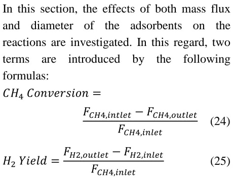
9.1. Effects of the mass flux and diameter of the adsorbents on components
In this section, the effects of both mass flux and diameter of the adsorbents on the reactions are investigated. In this regard, two terms are introduced by the following formulas:
𝐶𝐶𝐻𝐻4𝐶𝐶𝑚𝑚𝑀𝑀𝐶𝐶𝑒𝑒𝑟𝑟𝑠𝑠𝑖𝑖𝑚𝑚𝑀𝑀=
𝐹𝐹𝐶𝐶𝐻𝐻4,𝑖𝑖𝑛𝑛𝑡𝑡𝑚𝑚𝑒𝑒𝑡𝑡− 𝐹𝐹𝐶𝐶𝐻𝐻4,𝑜𝑜𝑜𝑜𝑡𝑡𝑚𝑚𝑒𝑒𝑡𝑡
𝐹𝐹𝐶𝐶𝐻𝐻4,𝑖𝑖𝑛𝑛𝑚𝑚𝑒𝑒𝑡𝑡 (24)
𝐻𝐻2𝑌𝑌𝑖𝑖𝑒𝑒𝑚𝑚𝑑𝑑 =𝐹𝐹𝐻𝐻2,𝑜𝑜𝑜𝑜𝑡𝑡𝑚𝑚𝑒𝑒𝑡𝑡𝐹𝐹 − 𝐹𝐹𝐻𝐻2,𝑖𝑖𝑛𝑛𝑚𝑚𝑒𝑒𝑡𝑡
𝐶𝐶𝐻𝐻4,𝑖𝑖𝑛𝑛𝑚𝑚𝑒𝑒𝑡𝑡 (25)
Figure 3 (a-e) illustrates the comparison of methane conversion percentage, H2 yield and
CO2 molar flow rates in the conventional
reactor (CR) and the GFSFBR in two different mass fluxes of flowing solids of 0.001 and 0.01
s m kg
.
2 . It should be mentioned that the
adsorbent diameter is fixed on 200 microns. Figure 3 (a) clearly shows that decreasing CO2
content over the catalysts surface increases CH4 conversion in the proposed reactor,
compared to the conventional process. Indeed, when CO2 is removed by adsorbents, the
equilibrium reactions are shifted toward more methane consumption, which subsequently leads to a rise in CH4 conversion. In fact, an
increase in the solid mass flux brings about an increase in the adsorbent presence. As a numerical report, at solid mass fluxes of 0.001 and 0.01(
s m kg
.
2 ), methane conversion increases
by about 17.61 % and 23.2 %, respectively. Figure 3 (b) is an illustration of hydrogen yield throughout the reactor length at different adsorbent mass fluxes. The GFFBR generally enhances the formation of desired product. However, at the entrance of the GFSFBR, adsorbents have negligible influence on the process performance in terms of hydrogen yield. Thus, GFSFBR operates nearly the same as CR because of the short contact time between both moving phases. Two different mass fluxes of 0.001 and 0.01(
s m kg
.
2 ) show
22 % and 29 % increase in hydrogen yield, respectively.
A comparison of the CO2 molar flow rate
along the GFSFBR and CR is presented in Fig. 3 (c). As seen, utilization of higher solids mass fluxes reduces the CO2 molar flow rate
Iranian Journal of Chemical Engineering, Vol. 13, No. 4 (Autumn 2016) 81 (a)
(b)
(c)
(d)
(e)
Figure 3. Comparison of (a) CH4 conversion, (b) H2 yield, (c) CO for S=0, 10-4, 10-3, 10-2 kg/(m2.s) and (d) H2 production and (e) CO2 molar flow rate for ds′= 200,400,1000 and 1400µmbetween CR and MR .
flux of 0.01 s m kg
.
2 is more suitable in the
mentioned interval owing to the higher hydrogen yield and methane conversion as well as lower CO2 molar flow rate.
Analyzing effect of adsorbents diameters is also added to the research. Three different solid diameters are applied to the model in the
Dimensionless length Dimensionless length
Dimensionless length
Dimensionless length Dimensionless length
CH
4
%
c
on
ve
rs
82 Iranian Journal of Chemical Engineering, Vol. 13, No. 4 (Autumn 2016) interval of 200 to 800 microns. It should be
noted that solid mass flux is chosen to be 0.01
s m kg
.
2 . Results from this trial can be seen in
Fig. 3(d-e).
These figures reveal that as solid particles become smaller, H2 production rate increases
and CO2 molar flow rate decreases which
proves adsorption improvement. The main reason of much adsorption is the increase in the contacting surface area between the adsorbents and gas phase in smaller particle sizes.
9.2. Effects of the mass flux and diameter of the adsorbents on pressure and temperature
In this section, the variation of temperature and pressure are discussed owing to their central role in the behavior of SMR reactions. Actually, the rate constants of the SMR reactions are a function of temperature and the rate equations of these reactions are influenced by partial pressure of the components.
As mentioned above, smaller size and higher mass flux of the adsorbents are likely to improve the performance of the reactor. Despite major advantages of any scientific phenomenon, it seems that the possibility of some disadvantages is inevitable. According to Fig. 4(a) and (b), the pressure drop along the GFSFBR length increases in comparison with CR. First, the adsorbents mass flux is kept constant and the GFSFBR operated at different adsorbents diameters. In the next step, a constant particle size of 200 microns was chosen and the mass flux varied (0.001
and 0.01 s m kg
.
2 ). The results clearly represent
that the smaller the particle size or the greater the mass flux of flowing solids to the reactor, the higher the bed resistance, which further results in an increase in drag forces. Consequently, the pressure drop increases through the column.
(a)
(b)
Figure 4. Gas phase pressure along the MR length for (a) S=0,10-4,10-3 and 10-2 kg/(m2.s) and (b)
s d′= 200,400,1000 and 1400µm.
Dimensionless length (m)
Iranian Journal of Chemical Engineering, Vol. 13, No. 4 (Autumn 2016) 83 As discussed previously, utilization of higher
mass fluxes or smaller diameters of the adsorbents reduce the carbon dioxide molar flow rate along the GFSFBR, which is in association with higher adsorption. Actually, smaller solid particles provide a better contact between the gas phase and surface area of the solids, and higher solid mass fluxes enhance the rate of CO2 adsorption. As a result, higher
methane conversion and subsequently higher required heat of reaction of the two first endothermic reactions is expected. Thus, a reduction in overall heat of reaction network is observed in spite of more heat of adsorption being released inside the reactor; however, in the meantime, an increase in the energy demand for the endothermic reactions overcomes the released energy which eventually causes temperature decrease. It is important to stress that the temperature reduction itself benefits from the adsorption strength of the sorbents. This is depicted in Figure 5 (a-b) in which the lower temperature profiles are observed as the solids mass flux increases or solids particle size decreases. In addition, it is concluded from the figures that the size of particles has only slight impacts on the temperature profiles. What is more, gas phase temperatures in the outlet of the GFSFBR are about 993.3, 999.7 and 1001(K) for adsorbent diameters of 200, 400 and 800 microns, respectively, which proves that the effect of the particle size on temperature is negligible in larger diameters. This fact is also observed in Fig. 5 (e) as the profiles of CO2
molar flow rates are almost identical.
9.3. Effect of the GFSFBR configuration on H2, CO, and CO2
(a)
(b)
Figure 5. Gas phase temperature along the MR length for (a) S=0,10-4,10-3 and 10-2 kg/(m2.s) and (b)ds′= 200,400,1000 and 1400µm.
According to the above-mentioned figures, with adsorbents’ mass flux of 0.01
s m kg
.
2 and
diameter of 200 microns, the molar flow rates of hydrogen and carbon dioxide, as the major components of this process, are plotted together in Fig. 6. This comparative figure vividly illustrates that the amount of produced H2 and adsorbed CO2 significantly increases
in GFSFBR configuration. Since hydrogen
Dimensionless length
84 Iranian Journal of Chemical Engineering, Vol. 13, No. 4 (Autumn 2016) can also be utilized as a clean fuel, any
increase in its production is favorable. Furthermore, the reduction in CO2 emission to
the atmosphere is an environmentally friendly phenomenon.
H2 (MR)
H2 (CR)
CO2 (CR)
CO2 (MR)
Figure 6. Comparison of H2 and CO2 molar flow rates in CR and MR (S=0.01 kg/(m2.s) and
s d′= 200µm).
Figure 7 shows a graph of the ratio of hydrogen to carbon monoxide as an important term in the reforming process. It is believed that, the higher the ratio of H2/CO, the more
favorable the system performance due to the higher hydrogen production rate with respect to that of carbon monoxide. The ratio increases about 47 % in GFSFBR owing to the adsorption which is desired for downstream units, especially methanol synthesis unit.
9.4. Effects of the inlet temperature of the gas phase
In this section, investigating the effects of a wide variety of parameters including the inlet temperature, pressure and the total flow rate on the adsorption capability have been taken into account. In this regard, possible advantages of the concept are discussed in terms of methane conversion as well as CO2
and H2 flow rate profiles along the GFSFBR
reactor.
Figure 7. Comparison of H2/CO ratio in CR and MR configurations (S= 0.01 kg/(m2.s) and ds′= 200µm).
Reactor length (m)
M
o
la
r f
lo
w
(
m
o
l/
s)
Iranian Journal of Chemical Engineering, Vol. 13, No. 4 (Autumn 2016) 85 Figure 8 (a-c) depicts 3-D schemes of the
influence of the flowing feed temperature on the above-mentioned parameters.
As the temperature increases, more energy is transferred to the reaction zone leading the endothermic reactions of (1) and (2) to a forward direction. As a result, CH4 conversion
as well as H2 and CO2 flow rates increase. As
known, it is not suitable for the system to produce a higher amount of CO2. The problem
is relatively modified by the WGS reaction that is exothermic in nature. Therefore, the slope of CO2 rise is slight.
As reported in Table 2, the temperature of 790 (K) is chosen to be the base case in the current study. According to Fig. 8(a), increasing the temperature of the prereformed gas stream to a sufficiently high value of 900 (K), the conversion enhances by about 19 %, that is highly acceptable. Moreover, at higher temperatures, the slope of conversion variation is steeper at the entrance region of the reactor that further results in an immediate conversion of the reacting components. Subsequently, in order to attain specific conversion percentage shorter reactor length is required. This statement is confirmed quantitatively by 22 % reduction in the length of the reacting tubes at 900 (K) with respect to the best case.
Conversion enhancement implies higher hydrogen production rates, a phenomenon that is represented by Fig. 8(b). A trend similar to that of CH4 conversion is observed by the 3-D
graph.
Thereupon, temperature rise is dramatically desirable for H2 production rate. It is
noteworthy that the temperature rise is not in favor of the adsorption. Thus, to promote the
SMR process, it is suggested to increase the inlet temperature of the bulk gas phase to an optimum value in which CO2 desorption is
negligible.
(a)
(b)
(c)
Figure 8. (a) CH4 conversion, (b) H2 production and (c) CO2 molar flow rate along the MR length in different inlet temperatures.
CH
4
%
c
on
ve
rs
86 Iranian Journal of Chemical Engineering, Vol. 13, No. 4 (Autumn 2016)
9.5. Effects of the inlet pressure of the gas phase
The profiles of CH4 conversion, H2 production
rate, and CO2 molar flow rate are plotted
versus the length of the reactor in the pressure range of 35 to 45 bar (Fig. 9 a-c). According to Le Chatelier’s principle, Eqs.1 and 2 occur in reverse direction by increasing the pressure, leading to CO, H2, and CO2 consumption
through the first and second SMR reactions. It is noticeable that the pressure variation does not affect the WGS reaction owing to the molar equality of the reactants and products. All the same, the reduction of CO production through Eq.1 is responsible for the lower amounts of H2 and CO2 production in Eq.3
(because it is one of the reactants in Eq.3). Therefore, both CO2 and H2 production
decrease by the ascension of the pressure. On the other hand, according to Eq.10, the in-situ removal of CO2 by the adsorption mechanism
is improved by increasing the pressure. Consequently, Eqs 2 and 3 are forced to take place in their forward direction that leads to higher H2 production. However, according to
the stoichiometry of the reaction network, the competition between the adsorption phenomenon and Le Chatelier’s principle finally causes a reduction in both H2 and CO2
flow rates (see Figs. 9(b) and 9(c)).
9.6. Effects of the inlet flow rate of the gas phase
The flow rate variation is also implemented in the model to determine possible effects on the process. Results are shown in 3-D plots of Fig. 10(a-b).
As expected, increasing the inlet flow rate
(a)
(b)
(c)
Figure 9. (a) CH4 conversion, (b) H2 production and (c) CO2 molar flow rate along the MR length in different inlet pressures.
CH
4
%
c
on
ve
rs
Iranian Journal of Chemical Engineering, Vol. 13, No. 4 (Autumn 2016) 87 of the gas phase induces shorter residence
time. Hence, the collision occurs in an insufficient period of time, resulting in inefficient collision between catalytic spheres and prereformed gas molecules. Accordingly, the reduction in the conversion of methane that is shown in Fig. 10 (a) is predictable. Taking a closer look at the graph, it can be understood that the influence of the feed flow rate on the conversion is considerably greater at lower amounts.
Additionally, the shorter residence time has another effect in terms of CO2 adsorption
through K2CO3 (see Fig. 10(b)). The curvature
that appears in the figure is due to the fact that sorbents are fresh at first, providing a higher driving force to adsorb CO2. Therefore, the
concentration of the adsorbed CO2 is rising.
But this increasing trend stops when sorbents become saturated according to the Langmuir equivalent adsorption model. At this point, sorbents are incapable of adsorbing further CO2 and need to be regenerated. The
saturation point occurs when the adsorbents pass approximately 60 % of the total reactor length. Afterwards, the GFSFBR operates similar to the CR. Also, the increase in the feed flow rate decreases the strength of adsorption negligibly by about 2 %. Although the value seems to be low at first glance, it induces its influence on the CH4 conversion as
a key parameter. Looking again at Fig. 9(a), a reduction of 57 % in the conversion is found. Although the only reason of conversion reduction is not the attenuation of the adsorption mechanism, its effectiveness cannot be neglected at all.
9.7. Optimization results
(a)
(b)
Figure 10. (a) CH4 conversion and (b) concentration of CO2 on the adsorbents along the MRlength in different total flow rates.
In this part, true Pareto optimal solutions and NSGA-II algorithm are compared for both TNK and KUR test problems. As seen in Fig. 11 (a) and (b), black curves of NSGA-II algorithm joined red lines of true Pareto front and covered the entire discontinuous domain on the true Pareto front for both test problems. Results of the other case studies are plotted in Fig. 12(a-c). All points on each curve present an optimal solution, and the curves are called Pareto set. In the first two figures, A and B show the points of single optimization
CH
4
%
c
on
ve
rs
88 Iranian Journal of Chemical Engineering, Vol. 13, No. 4 (Autumn 2016) (a)
(b)
Figure 11. Comparison of true Pareto optimal solutions with those obtained using the NSGA-II algorithm for (a) TNK test problem and (b) KUR.
on each Pareto set. At A, OF1 is at its
minimum value but OF3 is in its maximum
amount, in contrast to B. But as discussed earlier, achieving an optimum condition in which optimizing both objectives is considered simultaneously is more efficient. Thus, A´ and B´ are assigned to the figures.
These points and the others located between them are similarly good (non-dominating or non-inferior) and have approximate optimum values of both CH4 conversion and CO
selectivity (Fig. 14a), and H2/CO ratio and CO
selectivity (Fig. 14b). Optimum values of the midpoints are reported in Table 5 (second case study) and 6 (third case study) for decision variables and three objectives. It should be noted that points of the CR and GFSFBR conditions are set in the figures to clearly display the superiority of the conditions obtained by MO.
Also, the 3D plot of three objective functions is shown in Fig. 12(c).
Figure 13(a-g) illustrates the distribution of seven mentioned decision variables for the optimal solutions. The dispersion and accumulation of points are observed in figures retrieved from the conflicting nature of the decision variables. Regions in which density of points is high show the optimum intervals for each variable. According to the figures, optimum intervals of decision variables are approximately as follows:
Iranian Journal of Chemical Engineering, Vol. 13, No. 4 (Autumn 2016) 89 Table 5
Optimum values of operating conditions and objective functions for the midpoints between A´and B´.
Tg Ts S ds Ft Pt H/CO OF1 OF2 OF3
788.0564 849.2684 0.000618 486.734 2700.756 31.23066 0.476 34.61514 0.027349 14.94116
791.1224 848.062 0.000612 481.1366 2732.54 31.18906 0.475839 34.34266 0.027005 15.06143
786.928 836.3375 0.000623 481.2636 2897.132 31.2657 0.4776 31.80129 0.023708 16.40945
786.1529 843.7978 0.00057 455.549 2870.1 31.8478 0.476514 31.98569 0.024057 16.22169
783.9987 841.2394 0.000587 469.9619 2805.955 31.18505 0.476117 32.84853 0.025006 15.85284
784.2622 850.0448 0.000607 475.893 2868.068 31.04697 0.475535 32.03259 0.02396 16.30758
784.1171 854.5956 0.000604 465.9156 2902.621 31.04894 0.475054 31.56256 0.023379 16.57086
784.7253 842.8583 0.000602 468.4288 2773.546 31.24829 0.477992 33.37333 0.025664 15.58774
780.9751 832.2529 0.000537 434.0607 2874.778 31.89732 0.473993 31.55638 0.023521 16.46343
790.4208 843.5056 0.000563 463.495 2789.858 31.30344 0.473341 33.40958 0.025846 15.48749
790.6363 838.164 0.000586 481.4952 2865.967 31.22642 0.47761 32.45452 0.024555 16.02886
788.4167 838.885 0.000613 479.5106 2811.096 31.24481 0.477378 33.06138 0.025305 15.7226
786.9823 839.1889 0.00063 534.4786 2811.69 31.31073 0.47761 32.93311 0.025161 15.77584
784.7205 841.1306 0.00059 482.4189 2713.388 31.25084 0.476614 34.22146 0.026801 15.14535
790.0993 843.049 0.0006 490.079 2694.508 31.31814 0.474966 34.79893 0.027654 14.82101
785.8585 849.4541 0.0006 469.7778 2680.518 31.07075 0.475472 34.81308 0.027565 14.87513
793.5929 844.1533 0.000619 478.7347 2785.831 31.26829 0.477347 33.73939 0.026224 15.34953
788.3408 843.7978 0.00057 455.549 2870.1 31.8478 0.476514 32.12328 0.024246 16.13428
791.1306 851.5393 0.000587 456.3766 2876.973 31.1398 0.475593 32.336 0.024406 16.09462
787.516 835.4858 0.000621 465.1782 2738.327 31.48443 0.478163 34.01767 0.026561 15.22721
783.5188 847.9808 0.000558 463.6195 2914.859 31.06894 0.474951 31.3567 0.023139 16.6789
791.4332 842.9171 0.000592 484.581 2782.52 31.31962 0.475583 33.60493 0.02608 15.39899
785.1358 834.455 0.000611 461.9053 2755.597 31.64071 0.474882 33.52916 0.025988 15.43424
793.0786 844.634 0.000594 477.0392 2758.634 31.2344 0.47669 34.09105 0.026689 15.17329
783.1874 834.6718 0.000563 506.4173 2813.003 31.4341 0.47359 32.5904 0.024782 15.92168
790.2486 842.9643 0.000553 459.4786 2758.327 31.30693 0.476005 33.89477 0.026437 15.26686
786.1088 836.311 0.000593 459.7323 2742.846 31.4531 0.476759 33.8453 0.026345 15.30795
787.4099 842.0635 0.000597 467.6012 2795.795 31.25321 0.477105 33.21042 0.025491 15.64852
787.9951 847.0017 0.000626 479.1978 2798.836 31.30783 0.475336 33.16119 0.025467 15.65037
783.9987 841.2394 0.000587 469.9619 2822.365 31.18505 0.476117 32.62032 0.024717 15.97389
781.8425 833.0353 0.000593 456.8278 2899.396 31.65674 0.476713 31.36873 0.023216 16.62456
786.226 842.5612 0.000602 476.8279 2855.802 31.29442 0.475053 32.26226 0.024319 16.13105
787.7582 849.3634 0.000611 469.92 2838.533 31.17271 0.478599 32.67995 0.024779 15.94963
90 Iranian Journal of Chemical Engineering, Vol. 13, No. 4 (Autumn 2016) Table 6
Optimum values of operating conditions and objective functions for the midpoints between A´and B´.
Tg Ts S ds Ft Pt H/C F1 F2 F3
788.0564 849.2684 0.000618 486.734 2700.756 31.23066 0.476 34.61514 0.027349 14.94116
791.1224 848.062 0.000612 481.1366 2732.54 31.18906 0.475839 34.34266 0.027005 15.06143
784.7205 841.1306 0.00059 482.4189 2713.388 31.25084 0.476614 34.22146 0.026801 15.14535
790.0993 843.049 0.0006 490.079 2694.508 31.31814 0.474966 34.79893 0.027654 14.82101
785.8585 849.4541 0.0006 469.7778 2680.518 31.07075 0.475472 34.81308 0.027565 14.87513
787.516 835.4858 0.000621 465.1782 2738.327 31.48443 0.478163 34.01767 0.026561 15.22721
793.0786 844.634 0.000594 477.0392 2758.634 31.2344 0.47669 34.09105 0.026689 15.17329
790.2486 842.9643 0.000553 459.4786 2758.327 31.30693 0.476005 33.89477 0.026437 15.26686
786.1088 836.311 0.000593 459.7323 2742.846 31.4531 0.476759 33.8453 0.026345 15.30795
(a)
(b)
(c)
Figure 12. (a) Preto optimal fronts for (a) OF1 versus OF3, (b) OF2 versus OF3 and (3) all three objective functions.
10. Conclusions
The possibility of enhancing productivity of an industrial steam-methane reforming process was studied, employing the concept of sorption-enhanced reaction. A mathematical model of a GFSFBR was developed by considering plug flow patterns for moving phases (pre-reformed gas and adsorbents). It was observed that in the presence of flowing CO2 adsorbent particles, the process was
Methane conversion (%)
Iranian Journal of Chemical Engineering, Vol. 13, No. 4 (Autumn 2016) 91 (a)
(b)
(c)
(d)
(e)
92 Iranian Journal of Chemical Engineering, Vol. 13, No. 4 (Autumn 2016) (g)
Figure 13. Distribution of decision variables (Tg, T´s, S, ds, Ft, P, H2/CH4).
improved owing to higher methane conversion and hydrogen production together with lower CO2 emission. Moreover, variation of some
operating parameters was investigated along the axial direction of the reactor to analyze process sensitivity. Finally, results showed that higher mass flux of the adsorbents and inlet temperature as well as lower adsorbents’ diameter, inlet pressure and gas flow rate not only enhance methane conversion and hydrogen production, but also ameliorate adsorption of carbon dioxide. Multi-objective optimization was also performed on the model, using non-dominated sorting genetic algorithm-II. Following the purpose of maximizing three objective functions of CH4
conversions, CO selectivity and H2/CO ratio,
optimal operating conditions were reported in specific intervals. It can be claimed that this is the main strength of this approach.
Nomenclature
c
A cross section area of each tube [m2].
r
A
Archimedes number for flowing solid particles.s
a
′
specific surface area of flowing solid[m2/m3].
2
CO
b Langmuir model constant for component CO2 [Pa−1].
d
C
drag coefficient.g
p
C ′ specific heat of the gas at constant pressure [J/ (mol.K)].
s
p
C
′
specific heat of the flowing solid at constant pressure [J/(mol.K)].i
D
tube inside diameter [m].ij
D binary diffusion coefficient of component i in j [m2/ s].
im
D
diffusion coefficient of component i in the mixture [m2/s].eq
d equivalent diameter of packing particles.
s
d
catalyst diameter [m].s
d
′
flowing solid diameter [m].i
F
molar flow of species i [mol/s].t
F total molar flow per tube [mol/s].
ads
H
∆
specific heat of adsorption [J/mol].i f
H ,
∆ enthalpy of formation of component i [J/mol].
f
h′ gas–solid heat transfer coefficient [W/(m2 K)].
g
K conductivity of the gas phase [W.m/K].
g
k′ gas–solid mass transfer coefficient [m/s].
L length of reactor [m].
2
CO
m Langmuir model constant for component CO2 [mol/kg].
i
M molecular weight of component i [g/mol].
P total pressure [bar].
2
CO
q concentration of CO2 adsorbed in flowing solids [mol/kg].
*
2
CO
Iranian Journal of Chemical Engineering, Vol. 13, No. 4 (Autumn 2016) 93
R universal gas constant [J/(mol K)].
s e
R ′ Reynolds number of flowing solid.
i
r
reaction rate of component i [mol/(kg s)].S mass flux of flowing solids [kg/(m2.s)].
T bulk gas phase temperature [K].
s
T′ temperature of flowing solid [K].
g
u superficial gas velocity [m/s].
r
u relative velocity for co-current flow of gas and flowing solid [ur =ug −us′].
s
u′ real flowing solid velocity [ β ρs S
′ ].
x
molar composition.X methane conversion.
i
y
mole fraction of component i in the fluidphase [mol/mol].
z
axial reactor coordinate [m]. Greek lettersβ flowing solids holdup [β =βd +βs].
ε
void fraction of catalytic bed [m3/m3]. ε′ void fraction corrected due to presenceof the flowing solids (ε′=ε−β) [m3/m3].
ci
υ
critical volume of component i [m3/mol].µ
dynamic viscosity.B
ρ
catalytic bed density [kg/m3].g
ρ
gas density [kg/m3].S
ρ′
flowing solids density [kg/m3].φ
sphericity of packed bed element.References
[1] Wang, F., Qi, B., Wang, G. and Li, L., “Methane steam reforming: Kinetics and modeling over coating catalyst in micro-channel reactor”, Int. J. Hydrog. Energy,
38 (14), 5693 (2013).
[2] Bej, B., Pradhan, N.C. and Neogi, S.,
“Production of hydrogen by steam reforming of methane over alumina supported nano-NiO/SiO2 catalyst”,
Catal. Today, 207, 28 (2013).
[3] Song, C., Liu, Q., Ji, N., Kansha, Y. and Tsutsumi, A., “Optimization of steam methane reforming coupled with pressure swing adsorption hydrogen production process by heat integration”, Appl. Energy, 154, 392 (2015).
[4] Barelli, L., Bidini, G., Gallorini, F. and Servili, S., “Hydrogen production through sorption-enhanced steam methane reforming and membrane technology: A review”, Energy, 33 (4), 554 (2008). [5] Simpson, A.P. and Lutz, A.E., “Exergy
analysis of hydrogen production via steam methane reforming”, Int. J. Hydro. Energy, 32 (18), 4811 (2007).
[6] Hufton, J.R., Mayorga, S. and Sircar, S., “Sorption-enhanced reaction process for hydrogen production”, AIChE J., 45 (2), 248 (1999).
[7] Westerterp, K.R. and Kuczynski, M., “A model for a counter current gas-solid-solid trickle flow reactor for equilibrium reactions”, Chem. Eng. Sci., 42 (8), 1871 (1987).
[8] Ding, Y. and Alpay, E., “Equilibria and kinetics of CO2 adsorption on
hydrotalcite adsorbent”, Chem. Eng. Sci.,
55 (17), 3461 (2000).
[9] Gunduz, S. and Dogu, T., “Sorption enhanced ethanol reforming of ethanol over Ni- and Co-incorporated MCM-41 type catalysts”, Ind. Eng. Chem. Res., 51
(26), 8796 (2012).
94 Iranian Journal of Chemical Engineering, Vol. 13, No. 4 (Autumn 2016) “Hydrogen/methanol production in a
novel multifunctional reactor with in situ adsorption: Modeling and optimization”, Int. J. Energy Res., 38 (8), 978 (2014). [11]Dehghani, Z., Bayat, M. and Rahimpour,
M.R., “Sorption-enhanced methanol synthesis: Dynamic modeling and optimization”, J. Taiwan. Inst. Chem. Eng., 45 (4), 1490 (2014).
[12]Bayat, M., Dehghani, Z. and Rahimpour, M.R., “Sorption-enhanced methanol synthesis in a dual-bed reactor: Dynamic modeling and simulation”, J. Taiwan. Inst. Chem. Eng., 45 (5), 2307 (2014). [13]Van, D.D. and Staatsmijnen, D., French
Pat. 978287, Lumburg, (1948).
[14]Fourth methanol documents of Lurgi. Zagros Petrochemical Complex in Assaluyeh, Iran.
[15]Xiu, G.H., Lia, P. and Rodrigues, A.E., “Sorption-enhanced reaction process with reactive regeneration”, Chem. Eng. Sci.,
57 (18), 3893 (2002).
[16]Arab Aboosadi, Z., Rahimpour, M.R. and Jahanmiri. A., “A novel integrated thermally coupled configuration for methane-steam reforming and hydrogenation of nitrobenzene to aniline”, Int. J. Hydrog. Energy, 36 (4), 2960 (2011).
[17]Mbodji, M., Commenge, J.M., Falk, L., Di Marco, D., Rossignol, F., Prost, L., Valentin, S., Joly, R. and Del-Gallo, P., “Steam methane reforming reaction process intensification by using a millistructured reactor: Experimental setup and model validation for global kinetic reaction rate estimation”, Chem.
Eng. J., 207-208, 871 (2012).
[18]Gosiewski, K., Bartmann, U., Moszczynski, M. and Mleczko, L., “Effect of the intraparticle mass transport limitations on temperature profiles and catalytic performance of the reverse-flow reactor for the partial oxidation of methane to synthesis gas”, Chem. Eng. Sci., 54 (20), 4589 (1999).
[19]Ranz, W.E. and Marshall. W.R., “Evaporation from drops II”, Chem. Eng. Prog., 48 (141), 173 (1952).
[20]Claus, G., Vergnes, F. and Le Goff, P., “Hydrodynamic study of gas and solid flow through a screen-packing”, Can. J. Chem. Eng., 54 (3), 143 (1976).
[21]Predojevic, Z.J., Lj Petrovic, D. and Dudukovic, A.P., “Pressure drop in a countercurrent gas−flowing solids−packed bed contactor”, Ind. Eng. Chem. Res., 40 (25), 6039 (2001).
[22]Benali, M. and Shakourzadeh-Bolouri, K., “The gas-solid-solid packed contactor: Hydrodynamic behaviour of counter-current trickle flow of coarse and dense particles with a suspension of fine particles”, Int. J. Multiphase Flow, 20 (1), 161 (1994).
[23]Nikacevic, N., Jovanovic, M. and Petkovska, M., “Enhanced ammonia synthesis in multifunctional reactor with in-situ adsorption”, Chem. Eng. Res. Des., 89 (4), 398 (2011).
[24]Spasic, A.M. and Hsu, J.P., Finely dispersed particles. micro-, nano-, and atto-engineering, CRC Press, Taylor & Francis, Boca Raton, p.371 (2006).
Iranian Journal of Chemical Engineering, Vol. 13, No. 4 (Autumn 2016) 95 Chemical Engineers’ Handbook, 8th ed.,
McGraw-Hill, Singapore, p.420 (2008). [26]Cussler, E.L., Diffusion: Mass transfer in
fluid systems, Cambridge University Press, (1984).
[27]Wilke, C.R. “Estimation of liquid diffusion coefficients”, Chem. Eng. Prog.,
45 (3), 218 (1949).
[28]Reid, R.C., Sherwood, T.K. and Prausnitz, J., The properties of gases and liquids, 3rd ed., McGraw-Hill, New York,
(1977).
[29]Dudukovic, A.P., Nikacevic, N.M., Lj Petrovic, D. and Predojevic, Z.J. “Solids holdup and pressure drop in gas-flowing solids-fixed bed contactors”, Ind. Eng. Chem. Res., 42 (12), 2530 (2003).
[30]Perry, R.H. and Green, D.W., Perry’s Chemical Engineers’ Handbook, 8th ed., McGraw-Hill, Singapore, p.433 (2008). [31]Hartig, F. and Keil, F.J. “Large-scale
spherical fixed bed reactor: Modeling and optimization”, Ind. Eng. Chem. Res., 32
(3), 424 (1993).
[32]Rajesh, J.K., Gupta, S.K., Rangaiah, G.P. and Ray, A.K., “Multi-objective optimization of steam reformer performance using genetic algorithm”, Ind. Eng. Chem. Res., 39 (3), 706 (2000). [33]Luo, X., Hu, J., Zhao, J., Zhang, B.,
Chen, Y. and Mo, S., “Multi-objective optimization for the design and synthesis of utility systems with emission abatement technology concerns”, Appl. Energy, 136, 1110 (2014).
[34]Deb, K., Pratap, A., Agarwal, S. and Meyarivan, T., “A Fast and elitist multi-objective genetic algorithm: NSGA-II”, IEEE Trans. Evol. Comput., 6 (2), 182 (2002).
![Figure 1. A schematic diagram of the conventional steam reformer reactor (CR) configuration [14]](https://thumb-us.123doks.com/thumbv2/123dok_us/8886906.1823000/3.612.73.541.350.664/figure-schematic-diagram-conventional-steam-reformer-reactor-configuration.webp)