Amirkabir University of Technology (Tehran Polytechnic)
Vol. 47, No. 2, Fall 2015, pp. 9- 17
Amirkabir International Journal of Science& Research (Electrical & Electronics Engineering)
AIJ-EEE) )
*
FPGA Implementation of a Hammerstein Based Digital
Predistorter for Linearizing RF Power Amplifiers with
Memory Effects
A. Rahati Belabad
1, E. Iranpour
2and S. Sharifian
3*1- PhD. Student, Department of Electrical Engineering, Amirkabir University of Technology, Tehran, Iran 2- MSc. Student, Department of Electrical Engineering, Amirkabir University of Technology, Tehran, Iran 3- Assistant Professor, Department of Electrical Engineering, Amirkabir University of Technology, Tehran, Iran
ABSTRACT
Power amplifiers (PAs) are inherently nonlinear elements and digital predistortion is a highly
cost-effective approach to linearize them. Although most existing architectures assume that the PA has a
memoryless nonlinearity, memory effects of the PAs in many applications ,such as wideband code-division
multiple access (WCDMA) or orthogonal frequency-division multiplexing (OFDM), can no longer be
ignored and memoryless predistortion has limited effectiveness.
In this paper, a novel digital predistorter based on the Hammerstein structure has been proposed for
linearization of radio frequency power amplifiers with memory effect. Designing the Hammerstein model
based digital predistorter has been done using an accurate Wiener model of the power amplifier. The
proposed digital predistorter has many advantages such as low computational complexity, low memory space
and simple implementation. The elimination of nonlinear effects and constructing accurate behavioral model,
which is the exact inverse of a power amplifier characteristic, have been demonstrated by simulating 64
QAM constellation diagram in Matlab. In order to validate the proposed predistorter, it is implemented in
Kintex FPGA using Vivado HLS and acceptable results have been obtained.
KEYWORDS
efficiency are increasingly essential in the transmitters. Also, many of digitally modulated signals such as code division multiple access (CDMA) in the 3rd generation and frequency-division multiple access orthogonal (OFDMA) in the 4th generation were introduced to improve efficiency spectrum and data transmission rate [3]. Anyway, transmission of these non-constant envelop signals using linear power amplifiers does not have high efficiency because those have high peak to average power ratio (OFDM~10dB) and high back off is required to linear transmission [4]. Consequently to provide required linearity, utilization of high back off causes to decrease PAE of the power amplifier. In other words, it is well-known that high linearity will sacrifice the efficiency in power amplifiers. Therefore, design of the radio frequency power amplifier always has linearity and efficiency trade-off. The only solution for this problem is linearization. As a result, linearization techniques which allow power amplifiers to have both linearity and efficiency are very important.
Linearity methods such as feedback, feedforward and predistortion are utilized to improve linearity without efficiency degradation [5]. Among the linearity methods, a predistortion procedure has both high performance and low cost compared to other methods [6]. Indeed, the
A digital predistortion (DPD) approach is utilized to compensate nonlinear distortion which is generated by the power amplifier. This method is one of the most well-known digitally assistant analog approaches in the analog circuit design [7]. More recently, many of DPD models have been spread and the usage of the DPD linearization technique has been widely employed to linearize the power amplifier in the advanced radio transmitter [7]-[9]. An accurate modeling of power amplifiers is essential in order to create characteristic that exactly is the inverse of the power amplifier behavior. A power amplifier nonlinear modeling ,which includes Wiener, Hammerstein, parallel Hammerstein and memory polynomial, with memory effect have been widely utilized to model power amplifiers [10]-[13]. All of the methods are based on Volterra series to exhibit nonlinear systems. Lately, various structures of DPD have been proposed to compensate the memory effect and nonlinear distortion of power amplifiers [10]-[17]. These structures are neural network or polynomial based DPD and comprehensive study and detailed classification of behavioral modeling of power amplifiers and DPD have been illustrated in [18].
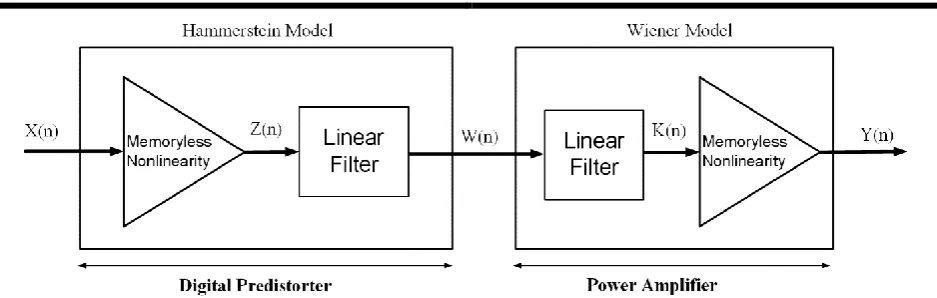
Power amplifiers with memory effect can be modeled using the Wiener structure that includes a linear filter and a memoryless nonlinearity [19]. The memoryless nonlinearity of the Wiener model is considered as phase and amplitude functions that they are nonlinear functions of the input signal amplitude. The advantage of the Wiener modeling for the PA is such that the corresponding predistorter is the Hammerstein system; i.e., a memoryless nonlinearity which is followed by a linear filter and it is possible for the predistorter to be an exact inverse of the PA behavior.
Since the field programmable gate array (FPGA) has many advantages in digital signal processing, including high density integration, parallel operation mechanisms,
high-speed processing (DSP), and flexible
implementation, the FPGA has become one of main choices for implementing baseband DPDs for RF Pas [20]. In this paper, we illustrate how to implement the proposed Hammerstein DPD model on FPGA chips, but the proposed technique is not only limited to FPGAs but also the same structure can also be readily implemented in other types of digital circuits, e.g., general DSP chips or application-specific integrated circuits (ASICs).
In this paper, a novel digital predistorter design based on direct learning structure using the Wiener model based power amplifier modeling is proposed. To validate the proposed structure, the suggested predistorter is implemented in field programmable gate array (FPGA) and it was simulated in Vivado high level synthesis (HLS) software. Actually, the proposed DPD method has little computational cost and makes simple VLSI hardware implementation.
The structure of this paper is organized as follows. Section 2 describes the Wiener power amplifier model and its predistorter model. Then in Section 3, FPGA implementation of proposed digital Predistorter is illustrated. In Section 4, simulation results extracted from Matlab and Vivado HLS tools are presented to make clear
the importance of the proposed structure. Finally, a conclusion is presented in Section 5.
2. WIENER POWER AMPLIFIER AND ITS PREDISTORTION DESIGN
A suitable model selection for the power amplifier is one of the most paramount parts in the digital predistorter design. Modeling of power amplifier has many methods which have complexity and precision trade-off. An appropriate model of power amplifier which considers both nonlinearity and memory effects is the Wiener model [19]. The Wiener model includes a linear filter followed by a memoryless nonlinearity. In order to model the power amplifier, Wiener model has been employed in the proposed digital predistortion system. An advantage of applying the Wiener model for DPD design is that the exact inverse system of the Wiener model can be represented by a memoryless nonlinearity followed by a linear system, which is known as the Hammerstein model
.
In Fig. 2, the use of Wiener model as a power amplifier and the Hammerstein model as a predistorter is illustrated. In fact, the main digital predistorter system is implemented using of the Wiener and Hammerstein model.
In the Wiener model, by applying the input signal
w(n) to the linear filter, the linear filter output k(n) is determined as follow
0
( )
(
)
n i i
k n
h w n i
(1)where hi are linear filter coefficients and the linear filter of order n indicates the memory effect on the input signal.
Signal applied to the memoryless nonlinear input part of the Wiener model is k(n). A Saleh model [21] has been
When passing through the linear filter, the input signal experiences memory effect. Then, the output signal of the linear filter passes to the nonlinear memoryless block and amplitude and phase of the signal according to AM/AM and AM/PM effect are changed. Finally, output signal y(n) considerably becomes distorted with respect to amplitude of the input signal r(n). The output signal can be expressed as
( ) | ( ) | .exp(
( ))
=
( ( )).exp( ( ( )
( ( )))
y n
y n
j y n
Amp r n
j
n
r n
(3)The output amplitude Amp(r(n)) and phase of the power amplifier
( ( ))
r n
y n
( )
( )
n
can be defined as follows, respectively [22].2
( )
1
a ar
Amp r
r
(4) 2 2( )
1
r
r
r
(5)The Amp(r) is changed proportional to 1/r and
( )
r
isapproximately constant for very large input p. Finally, nonlinear parameters of the Saleh model are defined as
a a
t
(6)According to the Wiener model designed for the power amplifier, proposed predistorter behavior should be exactly the inverse of the Wiener model characteristic. The proposed predistorter model is the Hammerstein structure consisting in the memoryless nonlinear block and the linear filter (Fig. 2) [23].
The linear filter of the Hammerstein predistorter should be exactly the inverse of the linear filter in the Wiener power amplifier model. Also, memoryless nonlinearity (phase and amplitude variation) of the
0 1 M
can be easily achieved by solving a set of linear equations as follow( ) . ( ) 1
G z
H z
(8)The memoryless nonlinear part of the Hammerstein predistorter should create appropriate phase and amplitude functions which fully compensate the phase and amplitude nonlinear functions of the Wiener power amplifier model that was expressed in equation (4) and (5). The input signal amplitude x(n) is denoted by b(n) and have magnitude of |x(n)|. The amplitude gain nonlinear function of the Hammerstein predistorter is denoted by p(b). Additionally, the amplitude predistorter function of memoryless nonlinear is equal to b.p(b) and phase predistortion function is equal to Ω(b). According to equation (6), a required equation for the amplitude predistortion function should be according to the following:
( . ( ))
Amp b P b
b
(9)Connecting the equation (9) into the equation (4) leads to
2 2
( )
1
( )
a a
bP b
b
b P b
(10)2 2
.
(b) -
. (b) + 1= 0
a
b P
aP
(11)Two solutions are achieved by solving the equation (11) so that the less solution is selected according to the required amplitude gain function.
2 2
4
b max 2
2
1 b max
( )
b
a a a
According to equation (5), required correction equation for phase predistortion function can be considered as follows:
( . ( ))
b P b
( )
b
0
(13)Based on equation (11) and (6), the solution of phase predistortion function Ω(b) is specified as
2
2
( ) ( . ( ))
( . ( ))
1 ( . ( )) b b P b
b P b b P b
(14)
The amplitude gain function of the predistorter, equation (12), includes a square root calculation and division by b2. When the signal b2 is close to zero, division by b2 causes a less accurate solution in the equation of (12). In order to simplify the hardware implementation, the calculation of P(b) without second root is very suitable. For this reason, equation (12) is expanded using the Taylor series expansion. At first, the function is defined as follows:
2 2
4 ab
a
w
(15)
With expanding
(1
w
2 1/ 2)
around w=0 by using the Taylor series and a condition of 1≥w, the amplitude gain function P(b) in the equation (12) can be expressed as follows:1
2( 1) 2 i
2 1 1
2 (4 )
( ) ( )
i n
i n
a i
i a
P b b o b
(16)where αI with (1≤i≤n) is positive constants and m is
the order of Taylor expansion. So, the amplitude gain function P(r) for b2≤A2max can be approximated as
follows
1 2 1
2 1
2
4
( )
(
) (
)
n
i i
i a
i a a
p b
b
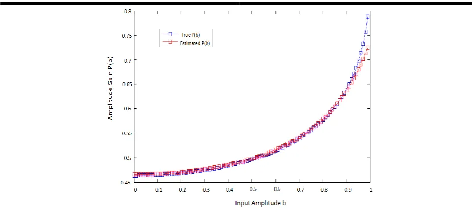
(17)Increasing the order of Taylor series n can improve performance of the proposed predistorter against increased cost of complexity of calculation. The amplitude gain P(b) and the Taylor approximation
( )
p b
with n=8 have been shown in Fig. 3. As seen in Fig. 3, the approximation error of Taylor series
( )
p b
which is denoted by
o b
(
2n)
is remarkable for inputs b>bsat. This approximation does not work as well to inputs close to the saturation point of the power amplifier. Therefore, the power amplifier must to work in operation points that are below its saturation point.3. FPGA IMPLEMENTATION OF THE PROPOSED PREDISTORTER
FPGAs are semiconductor devices that can be programmed based on the desired application or functionality requirements. FPGAs are suitable to design and implementation of a circuit in a short time, since they can be reprogrammed. Recently, because of these advantages, implementation of digital systems on FPGAs has been become very popular and in this article, we used FPGA to implement our design.
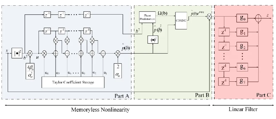
Fig. 4. The overall design of digital predistorter.
Recently, High-Level Synthesis (HLS) tools such as Vivado HLS [24] have made it possible to program FPGAs using C code instead of using VHDL/Verilog. HLS tools accept C syntax and generate a file format (typically VHDL/Verilog) that can be processed by the FPGA vendor software. HLS holds out the following promise: the ability to program in C while simultaneously achieving high performance and consuming low power.
HLS raises the abstraction level for hardware description promising significant shortening of the design cycle compared with RTL-based design entry. To achieve latency and resource utilization comparable to handwritten RTL, high-level synthesis often requires extensive code alterations and modification to ensure synthesizability. These are especially important for programs with irregular control flow and complicated data dependencies, which is the case of digital predictor.
Based on the equations described in the previous section, the overall design of digital predistorter is depicted in Fig. 4. The design consists of three parts. The part A accomplishes memory storage for the Taylor expansion coefficients and the implementation of the amplitude gain function. Equation (17) provides the effective structure to implement the memoryless nonlinear part of the Hammerstein structure. Using this equation, p(b) can be calculated in part A and proceed to the next stage. Implementation of the phase predistorter function Ω(b) using Equation (14) is performed in part B. The output of this part should be converted from Magnitude-Phase format to Real-Imaginary format. This operation is done in CORDIC block. The CORDIC IP implements a generalized coordinate rotational digital computer (CORDIC) algorithm, to iteratively solve trigonometric equations, including the hyperbolic and square root equations. Finally, the output of memoryless
nonlinearity part is obtained according to Equation (9). At the end, the LTI filter implementation is conducted in the part C using Equation (7).
The design is implemented using Vivado HLS. In order to compare utilized resources, the predistorter proposed in [23] also implemented on Kintex device. A summary of utilized resources for this implementation is presented in Table 1.
TABLE 1. RESOURCE UTILIZATION OF PROPOSED PREDISTORTER IMPLEMENTATION IN [23]
Name BRAM_18K DSP48E FF LUT
Expression - - 0 44
FIFO - - - -
Instance 13 67 9504 28075
Memory 0 - 384 32
Multiplexer - - - 1786
Register - - 1391 -
Total 13 67 11279 29937
As shown in Table 1, multiple DSP48E instances are used for the implemented design. DSP48E slices are full-custom and low-power, combining high speed with small size while retaining system design flexibility. The DSP slices enhance the speed and efficiency of many applications beyond digital signal processing, such as wide dynamic bus shifters, memory address generators, wide bus multiplexers, and memory-mapped I/O registers.
TABLE 2. RESOURCE UTILIZATION OF PROPOSED PREDISTORTER IMPLEMENTATION
Name BRAM_18K DSP48E FF LUT
Expression - - 0 34
FIFO - - - -
Instance 0 50 8541 17854
Memory 0 - 192 16
Multiplexer - - - 1323
Register - - 868 -
Total 0 50 9601 19227
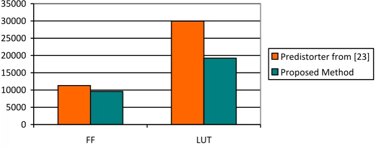
As it can be seen in Table 2, the proposed predistorter consumes fewer resources than the predistorter in [23]. Not only the proposed design does not need any BRAM block, but also it needs 40% less DSP48 instances than the previous one. A comparison of the number of FFs and LUTs utilized in implemented predistorters is shown in Fig.5.
4. SIMULATION AND IMPLEMENTATION RESULTS
In this section, simulation results for the proposed DPD in Matlab and Vivado HLS are presented.
A. Simulation Results
At first, the predistorter has been designed using the parameters mentioned for the Wiener power amplifier model. The linear filter length of the predistorter is selected equal to 7 (n=7). In order to create an appropriate trade-off between accuracy and simple implementation of the amplitude gain function, Taylor expansion order of seven (m=7) is selected using simulation. The
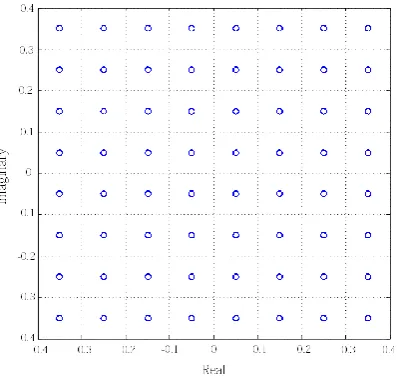
performance of predistorter can be evaluated by applying single carrier 64- QAM signal to the predistorter and taking the output of the Wiener power amplifier model. Constellation diagram of output signal after proposed predistorter and combined proposed predistorter and Wiener model have been illustrated in Fig.6 and Fig.7, respectively. It is clear from the figures that the proposed predistorter can completely compensate nonlinear distortion and memory effect of the power amplifier and constellation diagram of input and output signal is plenty identical using proposed digital predistorter.
B. Implementation Results
In order to validate the proposed DPD implementation, a test bench file is written in Vivado HLS to evaluate the results of the synthetized HDL code. To compare the results, the input data applied to the implemented system was identical to those used in MATLAB. Since Vivado HLS uses C code to program the FPGA device, testing the implemented design needs to be done by a C program. Therefore, the input data generated in Matlab is transferred to Vivado HLS via a text file. After calculating results by the implemented predistorter, the output data will be written in a text file and retrieved by Matlab. The output data from the implemented predistorter in FPGA and power amplifier have been shown in Fig.8 and Fig.9, respectively.
It is obvious that the constellation diagrams of Figure 6 and 8 are analogous to each other. However, the output of FPGA based system includes minor error in comparison with output constellation of the power amplifier in Matlab. By increasing the input magnitude of system, the output constellation deviates slightly from the expected position.
0 5000 10000 15000 20000 25000 30000 35000
FF LUT
Predistorter from [23] Proposed Method
Fig.6. Constellation diagram after proposed predistorter (input signal has 64 QAM modulation with n=10000)
Fig.8. Constellation diagram output for the implemented predistorter in FPGA (input signal has 64 QAM modulation
with n=10000)
Fig. 7. Constellation diagram after combined proposed predistorter and power amplifier Wiener model (input signal
has 64 QAM modulation with n=10000)
Fig. 9. Constellation diagram of system output using the implemented predistorter in FPGA (input signal has 64
QAM modulation with n=10000)
5. CONCLUSION
An efficient open-loop DPD has been presented in this paper. The novel digital predistorter based on the Hammerstein structure has been proposed for linearization of radio frequency power amplifiers with memory effect. Designing the Hammerstein model based digital predistorter has been done using an accurate Wiener model of the power amplifier. The proposed digital predistorter has many advantages such as low computational complexity, low memory space and simple implementation.
The elimination of nonlinear effects and constructing accurate behavioral model, which is the exact inverse of a power amplifier characteristic, have been demonstrated by simulating 64 QAM constellation diagram in Matlab. In order to validate the proposed predistorter, it is implemented in Kintex FPGA device by HLS in Vivado environment and acceptable results have been obtained. REFERENCES
[1] S. Afsardoost, T. Eriksson, and C. Fager, “Digital predistortion using a vector-switched model,” IEEE Trans. Microw. Theory Tech., vol. 60, no. 4, pp. 1166–1174, Apr. 2012.
Edition, September 2011.
[3] Chowdhury D, Hull CD, Degani OB, Wang Y, Niknejad AM. “A fully integrated dual-mode highly linear 2.4 GHz CMOS power amplifier for 4G WiMAX applications:. IEEE J Solid-State Circuits 2009; 44 (December (12)): 3393–402.
[4] Nazim Ceylan, inearization of power amplifiers by means of digital predistortion, Phd Dissertation, University of Nurnberg, Germany, 2005.
[5] H. Qian, H. Huang, and S. Yao, “A general adaptive digital predistortion architecture for stand-alone RF power amplifiers,” IEEE Trans. Broadcasting, vol. 59, no. 3, pp. 528–538, Sep. 2013.
[6] Rahul Gupta, Saad Ahmad, Reinhold Ludwig and John Mcneil, “Adaptive Digital Baseband Predistortion for RF Power Amplifier Linearization,” High Frequency Electronics, September 2006, pp. 16-25.
[7] Chao Yu, Michel Allegue-Martínez, Yan Guo and Anding Zhu, “Output-Controllable Partial Inverse Digital Predistortion for RF Power Amplifiers,” IEEE Transactions on Microwave Theory and Techniques, Vol. 62, no. 11, November 2014.
[8] J. Kimand K. Konstantinou, “Digital predistortion of wideband signals based on power amplifier model with memory,” Electron. Lett., vol. 37,no. 23, pp. 1417–1418, Nov. 2001.
[9] T.Liu, S.Boumaiza,and F.M.Ghannouchi,
“Augmented Hammerstein predistorter for
linearization of broadband wireless
transmitters,”IEEE Trans. Microw. Theory Techn., vol. 54, no. 4, pp. 1340–1349, Jun. 2006. [10] F. M. Ghannouchi and O. Hammi, “Behavioral
modeling and predistortion,” IEEE Microw. Mag., vol. 10, no. 7, pp. 52–64, Dec. 2009. [11] L. Ding, G. T. Zhou, D. R.Morgan, Z.Ma, J. S.
Kenney, J. Kim, and C. R. Giardina, “A robust digital baseband predistorter constructed using
memory polynomials,” IEEE Trans.
Communications, vol. 52, no. 1,pp. 159–165, Jan. 2004.
[12] M. Younes and F. M. Ghannouchi, “An accurate predistorter based on feedforward Hammerstein structure,” IEEE Trans. Broadcast., vol. 58, no. 3, pp. 454–461, Sep. 2012.
[13] L.Xu,X.Wu,M. Zhang,G.Kang, and P. Zhang, “A stable recursive algorithm for memory
polynomial predistorter,” in
Proc.MILCOM2007,Orlando, Florida, pp. 29-31, Oct.2007.
[14] H. Jiang, X. Yu, and P. A. Wilford, “Digital
predistortion using stochastic conjugate gradient method,” IEEE Trans. Broadcast., vol. 58,no. 1, pp. 114–124, Mar. 2012.
[15] R. Raich, H. Qian, and G. T. Zhou, “Orthogonal polynomials for power amplifier modeling and predistorter design,” IEEE Trans. Veh. Tech.,vol. 53, no. 5, pp. 1468–1479, Sep. 2004.
[16] Gilabert Pinal, Multi look-up table digital predistortion for RF power amplifier linearization. Phd Dissertation, Control
Monitoring and Communications Group
Department of Signal Theory and
Communications, Universitat Politecnica de Catalunya, 2007.
[17] L. Ding and G. T. Zhou, “Effects of even-order nonlinear terms on power amplifiermodeling and predistortion linearization,” IEEE Trans.Veh. Te chl., vol. 53, no. 1, pp. 156–162, Jan. 2004. [18] J. C. Pedro and S. Maas, “A comparative
overview of microwave and wireless power-amplifier behavioral modeling approaches,” IEEE Trans.Microw. Theory Tech., vol. 53, no. 4, pp. 1150–1163, Apr. 2005.
[19] C. J. Clark, G. Chrisikos, M. S. Muha, A. A. Moulthrop, and C. P.Silva, “Time-domain envelope measurement technique with application to wideband power amplifier modeling,” IEEE Trans. MicrowaveTheory and Techniques, vol. 46, no. 12, pp. 2531–2540, Dec. 1998.
[20] L. Guan, and A. Zhu, “Low-cost FPGA implementation of Volterra series-based digital predistorter for RF power amplifiers,” IEEE Trans. Microw. Theory Tech, vol. 58, no. 4, pp. 866 - 872, Apr. 2010.
[21] A. A. M. Saleh, “Frequency-independent and frequency-dependent nonlinear models of TWT amplifiers,” IEEE Trans. Communications,vol. COM-29, no. 11, pp. 1715–1720, Nov. 1981. [22] I. Teikari, “Digital Predistortion Linearization
Methods for RF Power Amplifiers” PHD Thesis, Helsinki University of Technology, 2008. [23] F. Taringou, O. Hammi, B. Srinivasan, R.
Malhame, and F.M.Ghannouchi, “Behavior modeling of wideband RF transmitters using Hammerstein–Wiener models,” IET Circuits, Devices Syst., vol. 4, no. 4,pp. 282–290, Jul. 2010.