International Journal of Industrial Electronics, Control and Optimization .
© 2019 IECO
….
Vol. 2, No. 4, pp. 289-296, Oct (2019)A Z-Source Network Integrated Buck-Boost PFC
Rectifier
Mohammad Babaei
1, Saeed Sharifi
2and Mohammad Monfared
3,†1,2,3 Department of Electrical Engineering, Ferdowsi University of Mashhad, Mashhad, Iran
This paper presents a wide range of gain buck-boost type PFC rectifiers based on the conventional buck-boost DC-DC converter. This novel rectifier is fed by a buck-type Z-source network at the DC side with the help of an inductor smoothing the AC side input current. The proposed PFC rectifier offers better input and output waveform qualities compared to the conventional buck-boost PFC rectifiers. Maintaining near to unity power factor (PF) and low total harmonic distortion (THD) in a wide range of load variations and also simple single-loop control are the main features of the proposed PFC rectifier. Furthermore, the switching frequency of the proposed rectifier can be chosen much higher than the competitors since it successfully allows increasing the duty cycle for the same voltage gain incredibly compared to the traditional solutions. This leads to a reduced size of passive components and volume of the rectifier. A 250 W prototype circuit is designed and simulated considering most practical issues to evaluate the performance of the proposed PFC in both buck and boost modes. The results that are compared with some well-known conventional PFC rectifiers confirm the superior performance of the proposed topology.
Article Info
Keywords:
Buck-Boost, Power Factor Correction, Rectifier, Z-source
Article History:
Received 2018-08-10
Accepted2018-12-24
I.
I
NTRODUCTIONPower factor correction (PFC) rectifiers have attracted attention for feeding most of the industrial DC loads up to hundreds of watts due to their low DC capacitor requirement, low harmonic injection to the grid, high power factor (PF), low electromagnetic interference (EMI), and at the same time, high-quality DC output voltage with minimum ripples. The PFC rectifiers are mainly utilized as the supply of data centers and communication equipment, uninterruptable power supplies (UPSs), electric vehicle (EV) drives, and telecom power supplies [1]-[3]. As is seen in Fig. 1, the main configuration of the PFC rectifiers consists of a diode bridge followed by a PFC circuit including buck, boost, buck-boost or other DC to DC converters. The boost-type PFC rectifier is mostly known as the best solution for power factor correction
in many applications due to purely sinusoidal current waveform drawn from the input source and considerably high power factor (PF) [4], [5]. However, its output voltage is higher than the peak AC input voltage while most of the industrial DC loads require lower voltages than the grid voltage. This necessitates employing an additional DC-DC converter to decrease its output voltage for the applications with low voltage operation. This additional DC-DC converter increases the weight and volume, and also decreases the efficiency and power density [6], [7]. Another solution for the aforementioned problem is the buck-type PFC rectifiers. Unfortunately, the buck-type PFC rectifier cannot provide as high-quality waveforms as that of the boost-type one. The input current THD and PF of the buck-type PFC rectifier are drastically worse than the boost-type one resulting in lower practical applications. As shown in Fig. 2, a problem known as the dead angle occurs for buck-type PFC rectifiers, which decreases the quality of the sinusoidal waveform of the AC input current of the buck-type PFC rectifier. In other words, since the output voltage of buck converters decreases to
†Corresponding Author: [email protected]
Tel: +98-38805017, Ferdowsi University
Department of Electrical Engineering, Ferdowsi University of Mashhad, Mashhad, Iran
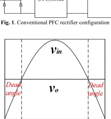
Fig. 1. Conventional PFC rectifier configuration
Fig. 2. Dead angle phenomena in a buck-type PFC rectifier.
lower values than the AC input voltage, the series switch of the buck converters cannot be turned on resulting in distortions of the AC input current [8]. In order to improve the input current quality of buck PFC rectifiers, another DC-DC converter, such as a buck-boost, a boost or a flyback connected in series or parallel to the main buck PFC rectifier, can be used [9]-[11]. This additional DC-DC converter improves the quality of input current but uses too many components. In addition to the dead angle problem, the absence of an input inductor significantly increases the input current THD compared to boost-type PFC rectifiers. Conventional buck-boost PFC rectifiers can provide lower or higher voltages than the AC input voltage simultaneously. These PFC rectifiers improve the performance and the quality of the waveforms as compared to other solutions although the lack of an input inductor in these rectifiers still causes AC input current distortions. Moreover, inverse output voltage polarity and the need for a high-side drive circuit for their power switch are the other shortcomings of these PFC rectifiers [5], [12].
This paper proposes an improved buck-boost type PFC rectifier fed from a Z-source network. This new configuration for the PFC rectifier mainly focuses on the improvement of the quality of the input and the output side waveforms. The principles of performance and different modes of operation are presented. Theoretical achievement is backed up with extensive simulations in PSIM software. The simulation results for both buck and boost modes of the proposed PFC rectifier are compared with the results for PFC rectifiers of [3], [13] and [14]. The input inductor helps reduce input
current THD and increase the power factor. This rectifier produces waveforms with higher quality than conventional rectifiers.
II.
P
ROPOSEDPFC
R
ECTIFIER A. Circuit ConfigurationThe proposed PFC rectifier configuration is composed of a diode bridge, a Z-source network, and a buck-boost type DC-DC converter, as shown in Fig. 3. The Z-source network is composed of an input inductor and a set of diode-switched-capacitors already proposed in [15]. The input inductor of the Z-source network helps reduce input current THD and increase the power factor (PF). Generally, due to the possibility of increasing the switching frequency, the capacitors of the Z-source network are considerably small so as not to contribute to the power loss of the converter. Also, the buck-boost type converter is utilized as the final stage of power conversion to regulate the input current and the output voltage. The performance and operation principles of the proposed PFC rectifier are analyzed below.
B. Operation Principles
Since the operation modes of the proposed PFC rectifier in each half cycle of the input voltage are the same, only the positive half cycle operation modes are discussed here for the sake of simplicity. Also, the DCM operation of the proposed PFC rectifier is analyzed as a general performance analysis since the CCM operation can be derived from it. On the other hand, by operating the rectifier in the DCM, several advantages can be obtained such as the intrinsic near-unity power factor and the zero current switching (ZCS). Thus, the turn-on transients and switching losses and the reverse
Fig. 3. Proposed Z-Source network integrated buck-boost PFC rectifier.
International Journal of Industrial Electronics, Control and Optimization .
© 2019 IECO
…
291recovery of the output diode are considerably reduced [8].
1) Mode I [0~DTs]:
As seen in Fig. 4, the switch SW is turned on and the diodes D3 and D4 are reverse biased, while D1 and D2 conduct. The input and output inductance, i.e. Lin and Lo, of the PFC rectifier are charged in this mode and their currents increase with a constant ramp. The voltage and current equations of this mode are written in Eq. (1) as in [15].
(1)
,
,
,
ˆ ˆ ˆ
ˆ ˆ
ˆ ˆ
ˆ ˆ ˆ
ˆ ˆ 1 2 1 2 1 2 o
Lin in c
Lo c
in Lin
Lo in c
o C
o o
V V V
V V
I I
I I 2 I
V I R C
2) Mode II [DTs~D'Ts]:
As depicted in Fig. 5, the switch SW is turned off and at the same time, the diodes D3 and D4 are forward biased and conduct while the diodes D1 and D2 block the voltages across the capacitors C1 and C2. The inductors Lin and Lo are discharged and their currents decrease. The inductor Lo current maintains higher than zero in this mode of operation. The voltage and current equations of this mode are given as
Eq. (2).
(2) ,
,
ˆ ˆ ˆ
ˆ ˆ
ˆ ˆ ˆ
ˆ
ˆ (ˆ )
1 2
1 2
o
Lin in c
Lo o
in Lin c
o
Lo c
o o
V V 2V
V V
I I I
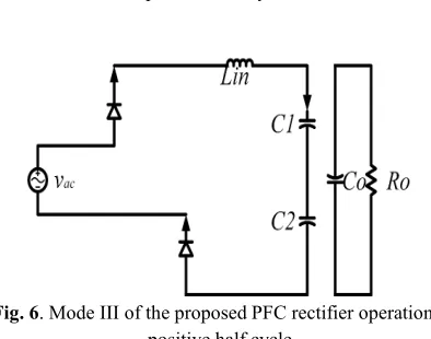
V I I R C 3) Mode III [D'Ts~Ts]:
The operation is similar to the mode II with the difference that the output inductor Lo current becomes zero, which translate to the DCM operation of the buck-boost-type converter. However, the input inductor Lin current decreases to a value higher than zero in this mode. This mode is shown in Fig. 6. According to Fig. 6, one can write Eq. (3).
(3) ,
ˆ ˆ ˆ
ˆ ˆ ˆ ˆ ˆ ˆ ˆ 1 2 o
Lin in c
Lo o in Lin Lo o C o o
V V 2V
V V I I I 0 V I R C
The voltage gain equation of the proposed PFC rectifier is obtained by applying the volt-second balance on the voltage across input and output inductors in modes I, II and III. Accordingly, the voltage gain equation, which is the ratio of the output to the input voltages, are given in Eq (4) in terms of the duty cycles (D and D').
(4) ˆ
ˆ (( ' ) ( )
' | ' | o in CCM m DCM s V D
D D 2 D
V
D 1
2L
D D
T R
III.
C
ONTROLM
ETHODThe conventional control method of the boost-type PFC rectifier operation in CCM is shown in Fig. 7. This control scheme known as the average current control (ACC) consists of a double closed-loop control plant. An individual proportional and integral (PI) controller is employed for the output voltage regulation as the outer loop and for the input Fig. 5. Mode II of the proposed PFC rectifier operation in
positive half cycle.
PI
PI
A B S A B Sv
ov
refv
ini
LPWM
Input Voltage feed-forward signal
Fig. 7. Conventional average current control method for the PFC rectifiers.
-6 -4 -2 0 2 4 6
i
in(1A/div)
v
in(50V/div)
Fig. 9. Input voltage and current of the proposed rectifier in the boost mode and 250 W load.
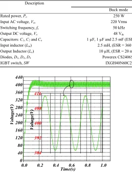
Table I.
SIMULATION CONDITIONS AND PARAMETERS. Values Description
Boost mode Buck mode
250 W 250 W
Rated power, Po
220 Vrms 220 Vrms
Input AC voltage, Vin
50 kHz 50 kHz
Switching frequency, fs
400 Vdc
48 Vdc
Output DC voltage, Vo
1 µF, 1 µF and 540 µF (ESR = 9 mΩ ) 1 µF, 1 µF and 2.5 mF (ESR = 19 mΩ)
Capacitors: C1, C2 and Co
1.5 mH, (ESR = 160 mΩ) 50 µH (ESR = 45 mΩ)
Powerex CS240650 IXGH40N60C2 2.5 mH, (ESR = 360 mΩ)
10 µH, (ESR = 20 mΩ,) Powerex CS240650
IXGH40N60C2 Input inductor (Lin)
Output Inductor (Lo)
Diodes, D1, D2, D3
IGBT switch, SW
0.0 0.2 0.4 0.6 0.8 1.0
0 40 80 120 160 200 240 280 320 360 400 440
384 392 400 408 416
V
ol
tage
(V
)
V
ol
ta
ge
(V
)
Time(s)
Fig. 8. Output voltage of the proposed rectifier in the boost mode and 250 W load.
AC current regulation as the inner loop. Similar to the SEPIC rectifier of [14], the proposed PFC rectifier can be well operated with only a single loop control scheme for output voltage regulation without requiring any current control loop. In other words, with DCM operation, the input current of the proposed PFC rectifier is maintained as a pure sinusoidal waveform due to the use of an input inductor at the DC side. This allows the input current to be proportional to the input voltage. Thus, the input current can synchronously track the sinusoidal form of the AC input voltage and produce near unity power factor. Also, the single loop control ability translates to two fewer sensors required for the closed-loop control procedure. In fact, only the output voltage sensor is required for the output voltage regulation.
IV.
P
ERFORMANCEE
VALUATIONInternational Journal of Industrial Electronics, Control and Optimization .
© 2019 IECO
…
2930.0 0.2 0.4 0.6 0.8 1.0 1.2 1.4
0 5 10 15 20 25 30 35 40 45 50
V
ol
tage
(V
)
Time(s) 46
48 50
V
o
lta
g
e(
V
)
Fig. 13. Output voltage of the proposed rectifier in buck mode and 250 W load.
THD is 5.5%. The input current of the conventional buck-boost PFC rectifier is also displayed in Fig. 10. As depicted in Fig. 10, the input current of the conventional
Fig. 10. Input voltage and current of the conventional buck-boost rectifier of [4] in boost mode and 250 W load
Fig. 11. Power factor comparison among the proposed, conventional boost PFC rectifier of [3] and sepic PFC rectifier of [14] for a 250 W load in boost mode.
buck-boost PFC rectifier absolutely contains switching harmonics, which significantly increases its THD. Consequently, the supremacy of the proposed PFC rectifier upon the conventional one is approved by comparing Figs. 9 and 10. Furthermore, the conventional boost PFC rectifier and the sepic PFC rectifier of [14] are also operated under the same conditions and then, THD and PF results are compared with the proposed PFC rectifier in Figs. 11 and 12. According to these figures, maintaining the input current THD and PF within the range of the standards for power quality from 20% of nominal load to full load is a remarkable feature of the proposed PFC rectifier. In addition to the above analysis, the buck mode operation of the proposed PFC rectifier is also simulated and the results are shown in Figs. 13 and 14. For a fair comparison with the buck-boost PFC rectifier of [5], both proposed and buck-boost PFC rectifier of [5] are operated for a nominal load power of 250 W and 48 Vdc. It should also be noted that the component parameters of the buck mode simulation for both proposed and buck-boost of [5] are
considered the same, where the input inductor Lin = 1.5 mH and output filter capacitor Co = 2.5 mF. As shown in Fig. 13, again the output voltage ripple of the proposed PFC rectifier is
Fig. 12. Input current THD versus load percentage comparison among the proposed, conventional boost PFC rectifier of [3] and sepic PFC rectifier of [14] for a 250 W
load in boost mode.
-6 -4 -2 0 2 4 6
i
in(1A/div)
v
in(50V/div)
smaller than 10%, which meets the needs of DC-loads. The input current THD of the buck-boost PFC rectifier of [5] is 6.3% while the proposed one offers an input current THD of as low as 5.5%. This low THD input current can be clearly expected from its waveform shown in Fig. 14. Also, the sepic PFC rectifier of [14] is operated under the same conditions and then, the THD and PF results are compared with the proposed PFC rectifier in Figs. 15 and 16. The results show that both rectifiers have good performance with a slightly improved quality of the input current for the proposed one.
The high efficiency of the rectification with the proposed PFC rectifier is verified in Fig. 17. The efficiency is obtained
with the various output loads as low as 40% to the nominal output power.
The obtained simulation results and the above analysis show that the proposed PFC rectifier is an improved solution of PFC rectification, which meets the loads and the power quality requirements.
V.
C
ONCLUSIONSThis paper introduced an improved buck-boost-type PFC rectifier that brings remarkable advantages for feeding DC-loads directly from the grid. This rectifier produces waveforms with higher quality than its conventional counterparts. The operation principles of the proposed PFC rectifier are presented and analyzed. Then, the simulations are presented in both modes of buck and boost to confirm its performance for two output voltage profiles and load powers. The simulation results confirm the superiority of the proposed converter over the conventional ones in providing high-quality input currents and output voltages without seriously sacrificing other practical concerns, such as the conversion efficiency and circuit simplicity.
R
EFERENCES[1] G. Sivanagaraju, S. Samata, L. M. Kunzler, K. R. Feistel, A. K. Rathore, and L. A. Lopes, “PFC interleaved buck-boost converter for telecom power application,” Proc. IECON 2017 - 43rd Annu. Conf. IEEE Ind. Electron. Soc., vol. 2017–Janua, pp. 2299–2304, 2017.
[2] S. Sharifi, M. Babaei, and M. Monfared, “A High Gain Buck PFC Synchronous Rectifier,” in Electrical Engineering (ICEE), Iranian Conference on, 2018, pp. 1185–1190.
[3] Y.-S. Kim, W.-Y. Sung, and B.-K. Lee, “Comparative performance analysis of high density and efficiency PFC topologies,” IEEE Trans. Power Electron., vol. 29, no. 6, pp. 2666–2679, 2014.
[4] C. Shi, A. Khaligh, and H. Wang, “Interleaved SEPIC Power Factor Preregulator Using Coupled Inductors in Discontinuous Conduction Mode with Wide Output Voltage,” IEEE Trans. Ind. Appl., vol. 52, no. 4, pp. 3461– 3471, 2016.
[5] Huai Wei and I. Batarseh, “Comparison of basic converter
topologies for power factor correction,” Proceedings IEEE Southeastcon ’98 “Engineering for a New Era.” pp. 348– 353.
[6] B. R. Ananthapadmanabha, R. Maurya, and S. R. Arya, “Improved Power Quality Switched Inductor Cuk Converter for Battery Charging Application,” IEEE Trans. Power Electron., vol. 8993, no. c, pp. 1–12, 2018. [7] J. Il Baek, J. K. Kim, J. B. Lee, H. S. Youn, and G. W.
Moon, “A Boost PFC Stage Utilized as Half-Bridge Converter for High-Efficiency DC-DC Stage in Power Supply Unit,” IEEE Transactions on Power Electronics, vol. 32, no. 10. pp. 7449–7457, 2017.
[8] Y. Jang and M. M. Jovanović, “Bridgeless
high-power-factor buck converter,” IEEE Trans. Power Electron., vol. 26, no. 2, pp. 602–611, 2011.
Fig. 15. Power factor comparison among proposed and sepic PFC rectifier of [14] for a 250 W load in buck mode.
Fig. 16. Input current THD versus load percentage comparison among the proposed and sepic PFC rectifier of
[14] for a 250 W load in buck mode.
International Journal of Industrial Electronics, Control and Optimization .
© 2019 IECO
…
295[9] X. Lin and F. Wang, “AC – DC bridgeless buck converter
with high PFC performance by inherently reduced dead zones,” pp. 1–7, 2018.
[10] X. Lin and F. Wang, “New Bridgeless Buck PFC
Converter With Improved Input Current and Power Factor,” vol. 0046, no. c, 2018.
[11] J. Zhang, C. Zhao, S. Zhao, and X. Wu, “A family of single-phase hybrid step-down PFC converters,” IEEE Trans. Power Electron., vol. 32, no. 7, pp. 5271–5281, 2017.
[12] R. Philip and C. Sreeja, “Single phase PFC using Buck-Boost converter,” 2014 Annual International Conference on Emerging Research Areas: Magnetics, Machines and Drives, AICERA/iCMMD 2014 - Proceedings. 2014.
[13] B. Zhao, A. Abramovitz, and K. Smedley, “Family of
Bridgeless Buck-Boost PFC Rectifiers,” IEEE
Transactions on Power Electronics, vol. 30, no. 12. pp. 6524–6527, 2015.
[14] A. J. Sabzali, E. H. Ismail, M. A. Al-Saffar, and A. A. Fardoun, “New bridgeless DCM sepic and Cuk PFC rectifiers with low conduction and switching losses,” IEEE Trans. Ind. Appl., vol. 47, no. 2, pp. 873–881, 2011.
[15] B. Axelrod, Y. Berkovich, and A. Ioinovici,
“Switched-capacitor/switched-inductor structures for
getting transformerless hybrid DC-DC PWM converters,” IEEE Trans. Circuits Syst. I Regul. Pap., vol. 55, no. 2, pp. 687–696, 2008.
Mohammad Babaei received B.Sc. in electrical engineering from Ferdowsi University of Mashhad, Iran, in 2016. He is currently an M.Sc. student at Ferdowsi University of Mashhad, Iran.
His research interests include power electronic converters, especially rectifiers, power supplies, AC-AC converters, and renewable energy systems.
Saeed Sharifi received both B.Sc. and M.Sc. degrees (with honors) in electrical engineering from Ferdowsi University of Mashhad, Iran, in 2015 and 2018, respectively.
His research interests include power electronic converters, especially impedance networks, high-order passive filters, grid-connected converters and AC-AC converters.
Mohammad Monfared (S’07–M’10-SM’15)
received the B.Sc. degree in electrical
engineering from Ferdowsi University of Mashhad, Iran, in 2004, and the M.Sc. and Ph.D. degrees (both with honors) in electrical engineering from Amirkabir University of Technology, Tehran, Iran, in 2006 and 2010, respectively.
![Fig. 12. Input current THD versus load percentage rectifier of [3] and sepic PFC rectifier of [14] for a 250 W comparison among the proposed, conventional boost PFC load in boost mode](https://thumb-us.123doks.com/thumbv2/123dok_us/16320.2001622/5.612.335.525.464.645/current-versus-percentage-rectifier-rectifier-comparison-proposed-conventional.webp)
![Fig. 15. Power factor comparison among proposed and sepic PFC rectifier of [14] for a 250 W load in buck mode](https://thumb-us.123doks.com/thumbv2/123dok_us/16320.2001622/6.612.73.286.62.184/fig-power-factor-comparison-proposed-sepic-pfc-rectifier.webp)