Vol. 48, No. 2, Fall 2016, pp. 81-91
Please cite this article using:
Fathi, M., Ghahramani, N., Ashtiani, M. A. S., Mohammadi, A., and Fallah, M., 2016. “Adaptive Fusion of Inertial Navigation System and Tracking Radar Data”. Amirkabir International Journal of Electrical and Electronics Engineering, 48(2), pp. 81–91.
DOI: 10.22060/eej.2016.818
URL: http://eej.aut.ac.ir/article_818.html
*Corresponding Author, Email: [email protected]
Adaptive Fusion of Inertial Navigation System and Tracking
Radar Data
M. Fathi1,*, N. Ghahramani2, M. A. S. Ashtiani3, A. Mohammadi4, M. Fallah5
1- Ph.D. Candidate, Department of Aerospace Engineering-Flight Mechanics and Control Group, Malek Ashtar University of Technology 2- Associate Professor, Department of Electrical Engineering-Control Group, Malek Ashtar University of Technology
3- Associate Professor, Department of Aerospace Engineering-Flight Mechanics and Control Group, Malek Ashtar University of Technology 4- Assistant Professor, Department of Electrical Engineering-Control Group, Malek Ashtar University of Technology
5- Assistant Professor, Department of Electrical Engineering-Communication Group, Malek Ashtar University of Technology
(Received 10 October 2015, Accepted 29 May 2016)
Against the range-dependent accuracy of the tracking radar measurements including range, elevation
and bearing angles, a new hybrid adaptive Kalman filter is proposed to enhance the performance of the radar aided strapdown inertial navigation system (INS/Radar). This filter involves the concept of residual-based adaptive estimation and adaptive fading Kalman filter, and tunes dynamically the filter
parameters, including the fading factors and the measurement and process noises scaling factors based on the ratio of the actual residual covariance to the theoretical one. In fact, due to the unknown and fast-varying statistical parameters of the radar measurement noises and their nonlinear characteristics,
apply-ing a conventional Kalman filter to INS/Radar fusion yields a low-performance navigation and in-flight
alignment. The Monte Carlo simulation results of the integrated navigation system on an interceptor missile trajectory indicate the new algorithm has an effective performance in the face of nonlinearities
and uncertainties of the tracking radar measurements. These results allow knowing whether the fine in-flight alignment and high-performance navigation can be possible for the long-range air defense missile
using the low-cost INS/Radar system without aiding global navigation satellite system signals.
KEYWORDS:
Adaptive Kalman Filter, Inertial Navigation, In-flight Alignment, Radar
1- Introduction
It is widely accepted that the modern long-range air defense missiles will require a two-phase guidance strategy employing a mid-course phase followed by terminal homing. These tactical missiles will require an on-board strapdown inertial navigation system, INS, to perform the functions, such as the provision of the data for a navigation of the missile prior to a period of terminal homing, provision of homing head pointing commands and provision of autopilot feedback signals [1].
Due to INS intrinsic defect and special mission of an anti-air missile, four problems can appear. First, INS navigation errors propagate as a result of instrument errors, initial alignment error, and imperfections in the strapdown computing algorithms. Second, many air defense missiles require an accurate alignment of the onboard INS in order to achieve a high probability of killing against their intended targets [2]. Third, air defense systems require rapid reaction time, thus
significant pre-launch delays for alignment are not
tolerable [2]. Fourth, typically, such tactical systems require medium grade inertial quality instruments (high cost) to carry out their functions and to ensure
an accurate transition to the terminal phase of flight.
As a solution to overcoming these problems, the tracking radar (radio detection and ranging) aided INS was presented in [1,3]. In this particular application, the launch platform can provide only a very coarse initialization for the missile’s INS then the missile is
fired to intercept an intended target. The missile and
the target are tracked by a ground-based radar system. The radar provides measurements of missile range, elevation and bearing with respect to the radar set. These measurements may be passed to the missile via an uplink transmitter and used to aid the on-board INS. The missile on-board inertial navigation system
implements a Kalman filter to determine in-flight
corrections to the navigation errors.
Several studies have been conducted on INS/
Radar to gain the benefits of in-flight alignment of INS, in-flight calibration of INS, improvement of INS performance and in-flight registration of radar frame
with navigation frame.
Both the in-flight alignment by INS/Radar
integration and the pre-launched alignment by shipboard measurements for a ship launched missile’s INS are developed and their relative merits are compared in [1]. The subject of [2-8] is related to the development of a radar and GPS (global positioning
system) aided INS for a navy tactical ballistic missile defense interceptor missile (Standard Missile SM-3). An overview and a preliminary performance assessment of an INS/Radar/GPS system based on
a direct Kalman filter with 20 states are provided
in [3]. The research in [2,4] proposes a new metric to determine the degree of observability of attitude
errors in flight alignment of INS/Radar/GPS over specified missile flight profiles. In-flight alignment
of an onboard INS using the external radar and GPS
data and a conventional Kalman filter for data fusion
have been explained in detail in [5,6]. Sure enough,
a cornerstone to the in-flight alignment was laid out
in [7-9] which addressed the question: what kind
of horizontal maneuver is preferable in the in-flight
INS alignment; the interested reader is directed to these references for a more detailed discussion of
in-flight alignment. The references [10,11] discuss the successful flight test results of the INS/Radar/
GPS system for the missile SM-3. A strapdown INS augmentation scheme comprising astronavigation system and secure radio positioning system is proposed in [12]. Also, the issue of the Mars entry navigation using integration of information sensed from radio beacons and information derived from inertial measurement unit is addressed in [13].
All the above-mentioned researches relevant to the integration of INS and radar data assume that the measurement noise covariance matrix (R) in the
Kalman filter is fixed. In other words, it is supposed
that the tracking radar measurements have constant standard deviations. However, it is well known that the radar measurements accuracies are very range depended [14, chapter 11], [15, chapter 4]. Indeed, the accuracies of range and angles (elevation and bearing) measured by the radar are the functions of the range (see section 2 for the details). It means the
matrix R should be a varying matrix, not a fixed one. Insufficient a priori information about this
varying matrix R affects the accuracy of the INS/
Radar integrated system. In fact, insufficiently known a priori filter statistics will reduce the precision of the estimated filter states or introduce biases to their
estimates [16]. In addition, wrong a priori information
will lead to the practical divergence of the filter. For
example, if R is too small at the beginning of the estimation process, the uncertainty tube around the true value in a probabilistic sense will tighten and a
biased solution will result. If R is too large, a filter
Besides, it will result in a longer estimation transition
for the filter whose total operation time is very short
(about 1 to 3 minutes for a long-range air defense
missile flight). These minute points imply that using a fixed filter designed by conventional methods
for an INS/Radar system with the changing radar measurements accuracies is a major drawback.
From this point of view, this study proposes that
the fixed estimation formulation for the INS/Radar
integrated system has resulted in a poor estimation performance and should be replaced by an adaptive
estimation filter with a varying measurement noise
covariance matrix. It can be expected that with the adaptive fusion scheme, a better navigation performance can be achieved.
The paper is organized as follows. In section II, the tracking radar is introduced and the measurement
errors of a specific tracking radar are analyzed. Section
III outlines the residual-based adaptive estimation
/ the adaptive fading Kalman filter hybrid method
(RAE/AFKF) which is the main contribution of this paper. In section IV, the process and measurement model for INS/Radar integration system are provided. In section V, the performance of RAE/AFKF is evaluated in Monte Carlo simulations compared with
an extended Kalman filter, EKF. Finally, section VI
provides concluding remarks.
2- An assessment of tracking radar
measurement errors
A typical tracking radar has a pencil beam to receive echoes from a single target and tracks the target in angle, range, and/or doppler. Discussion in [15, chapter 4] and [17, chapters 8, 9] shows that the several major effects on the accuracy of the tracking radar measurements are as follows:
• Glint, or angle noise which affects all the
tracking radars especially at a short range. The error due to glint varies inversely with the range.
• Receiver noise which also affects all the radar
types, and mainly determines to track accuracy at the long range. The receiver noise causes the error to vary as the square of the range.
• Amplitude fluctuations of the target echo that
bother the conical-scan and sequential lobing type of radars, but not the monopulse type. The amplitude
fluctuations effect is independent of the range. • Clutter and multipath effects;
• Servo noise and servo lag of tracking
mechanism; the servo noise is independent of the
range.
The contribution of glint, receiver noise and
amplitude fluctuations to the accuracy of a tracking
radar as a function of range is illustrated in Fig. 1. Fig. 1 is a very qualitative plot showing the general nature of each of these factors, while precise investigations of tracking errors associated with a particular monopulse phased-array radar system and with the radar AN/FPS-16 are discussed and presented in [18] and [14, page 11-12], [19, pages
48-94], respectively. But the specific operating
conditions assumed in [14,18,19], such as the target radar cross section, RCS, and altitude are not compatible with what this research needs. Thus, based on the free-space performance analysis and the missile target RCS, standard deviation (STD) of the total angle and range errors of the tracking radar An/ FPS-16 as a function of range are roughly estimated as illustrated in Figs. 2 and 3 (see appendix A for the radar equations). Although this radar is one of the early monopulse radars, it remains in a wide use and represents one of the most accurate tracking devices employed in the test-range instrumentation. Its major parameters are listed in [17, pages 542-543].
3- INS/Radar adaptive integration system
As mentioned in section I, due to the unknown range-varying statistical parameters of the radar measurement noises, applying the EKF to INS/Radar integration results in a low-performance estimation. In order to enhance its performance, this unknown and variable statistical parameter needs to be estimated and adapted with the system state and the error covariance. Two popular types of the adaptive
Kalman filter algorithms include the
innovation-based adaptive estimation, IAE, approach and the
Fig. 3. A rough estimation of the tracking range error STD for the AN/FPS-16 in free-space analysis Fig. 2. A rough estimation of the tracking angle error
STD for the AN/FPS-16 in the free-space analysis
adaptive fading Kalman filter, AFKF, approach [20].
The innovation sequences in IAE method have been utilized by the correlation and covariance-matching techniques to estimate the noise covariance. The basic idea behind the covariance-matching approach is to make the actual value of the covariance of the innovation consistent with its theoretical value. The
implementation of IAE-based adaptive Kalman filter,
IAKF, to navigation designs has been widely explored in [16,21]. The idea of AFKF is to incorporate suboptimal fading factors as a multiplier into the predicted covariance matrix to deliberately increase the variance of the predicted state vector to enhance
the influence of innovation information and improve
the tracking capability in high dynamic maneuvering [22].
In this study, the methods IAKF, AFKF and
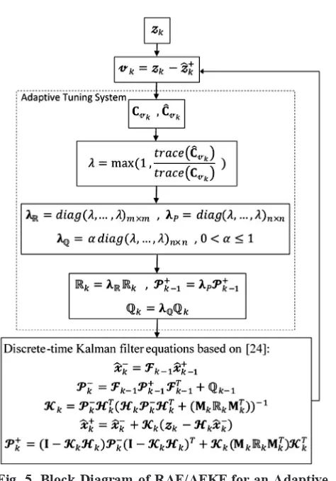
the hybrid approach IAE/AFKF developed in [23] were applied to INS/Radar integration problem as none of them solely was able to satisfy the desired performance. Therefore, a new hybrid approach involving the concept of residual-based adaptive estimation, RAE, and AFKF is presented. The ratio of the actual residual covariance based on the sampled sequence to the theoretical residual covariance will
be employed for dynamically tuning three filter
parameters, including fading factor (λP), measurement noise scaling factor (λR) and process noise scaling factor (λQ). To provide these factors, the Kalman
filter approach is coupled with the adaptive tuning
system, ATS. In the ATS mechanism, the adaptations on the error states covariance matrix (P), on process covariance matrix (Q) and on the measurement noise covariance are involved. The idea is based on
the concept that when the filter achieves estimation
optimality, the actual residual covariance based on the sampled sequence and the theoretical residual covariance should be equal.
3- 1- Integration algorithm
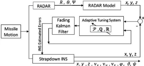
As shown in Fig. 4, the position states of INS, i.e. x, y, z, may be compared with the same quantities obtained from a radar model. This model converts the radar measurements of the radar Polar coordinate system into the radar Cartesian one using x=RcosΘsinΨ, y=RcosΘsinΨ and z=-RsinΘ where R, Θ and Ψ are range, elevation, and bearing, respectively.
The differences between the actual and
predicted measurements are the filter measurements
innovations. These quantities are multiplied by the Kalman gains to provide estimates of the errors in the INS indicated position, velocity, and attitude.
Also, because of insufficient knowledge of the
radar measurement noise statistics, a residual-based adaptive tuning system effectively adapts R, Q and
P to compensate such lack of information. Finally, the estimates of the errors are subsequently used to correct the INS solutions over time, and update takes place following the arrival of each radar measurement of the missile positions.
3- 2- ARAE/AFKF hybrid algorithm
The process model and measurement model are represented [24, chapter 4] as:
(1)
(2) where the state vector xk∈Rn, process noise vector
wk ∈Rn, measurement vector z
k∈Rm, and measurement noise vector vk∈Rm. In Eqs. (1) and (2), both the vectors
wk and vk are zero mean Gaussian white sequences having zero cross-correlation with each other:
(3)
(4)
(5) where Qk is the process noise covariance matrix, Rk is the measurement noise covariance matrix, F is the state transition matrix, E [.] represents expectation and superscript “T” denotes matrix transpose. From the measured zk and the predicted measurement ẑk+=H
kxk+ based on the updated filter states xk+, the
residuals sequence is defined as vk=zk-ẑk+. Also, the
theoretical covariance matrix of the residual sequence, developed in [16], is given by:
(6)
Defining Ĉvk as the statistical sample variance estimate of Cvk, matrix Ĉvk can be computed by averaging inside a moving estimation window of size
N:
(7)
where N is the number of samples (usually referred to the window size); j0=k-N+1 is the first sample inside
the estimation window. The window size N is chosen empirically to give some statistical smoothing.
The block diagram of RAE/AFKF hybrid method and further details regarding the residual-based
adaptive tuning system loop are illustrated as a flow
chart in Fig. 5.
where Pk is the error covariance matrix defined by E[(xk-x̂k) (xk-x̂k)T], in which x̂
k is an estimation of the
Fig. 5. Block Diagram of RAE/AFKF for an Adaptive Estimation
system state vector xk, and the weighting matrix Kk is generally referred to as the Kalman gain matrix. Also, the value 0<α≤1 is determined empirically through
computer simulation.
4- Mathematical modeling
In this section, linear differential equations of the INS are derived and are presented as the process model. Also, the measurement model based on the difference between the radar and the INS measurements is obtained.
4- 1- Process modeling
The tangent coordinate frame (t-frame) is defined to be an earth-fixed which is aligned with a geographic frame at the fixed location missile launcher on the
earth. In this system, the navigation equations are [25, chapter 3]:
t-frame:
(11)
Lf, Ω and fb represent latitude of the missile
launcher location, earth’s rate, and the specific force
in the missile body frame, respectively. Also ωtbb is the turn rate of the body with respect to the t-frame; Ωtbb is the skew-symmetric form of ω
tbb, Cbt which is a direction cosine matrix to transform the measured
specific force vector to navigation axes (t-frame) and glt represents the gravity field vector.
The linearized differential Eqs. (8) to (10) are:
(12)
(13)
(14)
(15)
(16) where G and gn are the gravity gradient matrix and the gravity vector referenced in the local level geographic frame (n-frame), respectively. Although G may be negligible for a low cost or tactical grade INS, in Appendix B a new model for G is derived. δrt and δvt are the INS position and velocity errors, and ϕ is the body-to-navigation attitude error. ε is defined
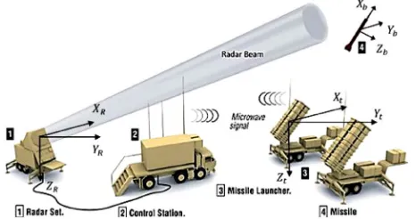
as the error vector in the transformation between the radar face and navigation coordinate frames. The components of ε are the misalignment errors between them as shown in Fig. 6. Superscripts or subscripts t,
R and b denote the tangent, radar and body frames, respectively. wa and wg are accelerometers and gyros noise vector. Eq. (12) in discrete-time domain takes the form Eq. (1) using the error state vector expressed in component form as x=[δrt δvt ϕ ε ] T.
4- 2- Measurement modeling
The radar outputs are combined with INS positions to form a measurement for processing in an onboard
Fig. 6. Radar, navigation and body frames, background image courtesy Raytheon company copyright© 2002
Kalman filter algorithm. The difference between the
radar and INS measurements in the navigation frame t is expressed as:
(17)
(18)
where, the radar provides measurements in the polar coordinate system, i.e. the measurements of range, R, elevation, Θ, and bearing, Ψ.
Cartesian quantities may be expressed in terms of the polar coordinates as follows:
(19)
Expanding Eq. (17) about a nominal position r and neglecting products of error quantities yields:
(20)
where
(21)
(22)
(23)
v represents the error in the radar measurements.
direction cosine matrix between the radar frame and the navigation axes (t-frame). In this research, the matrix CRt is assumed time-invariant due to the
fixed ground base of the radar station and the missile
launcher.
5- Simulation studies
In this section, firstly the flight trajectory needed
for navigation simulation is introduced. Then, the
specifications of inertial sensors and the tracking
radar are presented. Finally, the simulation results of INS/Radar adaptive integration navigation system are displayed and discussed.
5- 1- Flight trajectory
Fig. 7 illustrates the representative scenario used
in the simulation analyses. Over the period of flight,
the missile under proportional guidance laws follows a boost phase and intercepts a maneuvering target. The missile’s integration inertial navigation system before second 4 is in the INS only mode and after receiving the radar data in the second 4 switches to INS/Radar mode.
5- 2- Sensor specifications
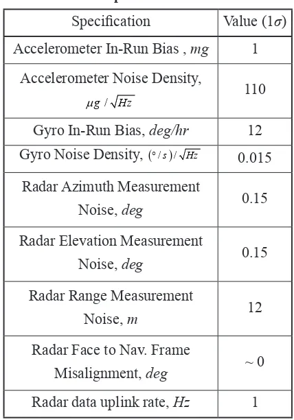
The low- cost inertial sensors specifications of INS
are presented in Table 1. For the radar measurements simulation, we use the information given in Figs. 2
and 3. But, the design of an extended Kalman filter for the INS/Radar integration needs the fixed radar measurements specifications which are listed in Table
1. Also, owing to preliminary alignment between the
ground-fixed radar frame and navigation frame, it is
supposed that the misalignment ε is negligible.
Fig. 7. The missile trajectory
Table 1. Inertial sensor and radar measurement specifications
Specification Value (1σ)
Accelerometer In-Run Bias , mg 1 Accelerometer Noise Density,
/
g Hz
µ 110
Gyro In-Run Bias, deg/hr 12 Gyro Noise Density, (°/ /s) Hz 0.015
Radar Azimuth Measurement
Noise, deg 0.15
Radar Elevation Measurement
Noise, deg 0.15
Radar Range Measurement
Noise, m 12
Radar Face to Nav. Frame
Misalignment, deg ~ 0
Radar data uplink rate, Hz 1
5- 3- Simulation results
Time domain Monte Carlo, MC, and the simulations of the INS/Radar integrated navigation system are carried out to compare the performance
of RAE/AFKF, EKF and a new definition filter under
the title of ideal EKF, IEKF. In fact, the EKF and IEKF display more or less two boundaries in the simulation results for evaluating the performance of RAE/AFKF. In the IEKF, unlike RAE/AFKF and EKF, it is supposed that the true radar measurements accuracy in every range conforming to Figs. 2 and 3 is known and the measurement noise covariance matrix
of the filter is improved in every second based on this
existing and virtual information. In other words, the ideal EKF can be equal to an adaptive EKF whose matrix R is only adapted and its estimation about R
is definitely precise, accurate and similar to the real
radar measurements accuracy, i.e. Figs. 2 and 3. Hence, the IEKF represents how good the navigation performance can be if such excellent information about the accuracies of the radar measurements is estimated and provided for the EKF disregard of
the estimation method. Therefore, this virtual filter highlights the capacity of adaptive filters in the
navigation system.
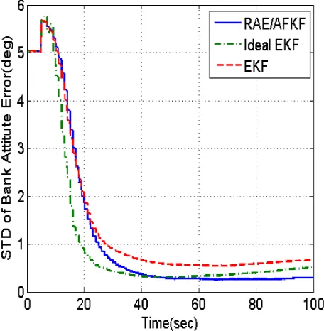
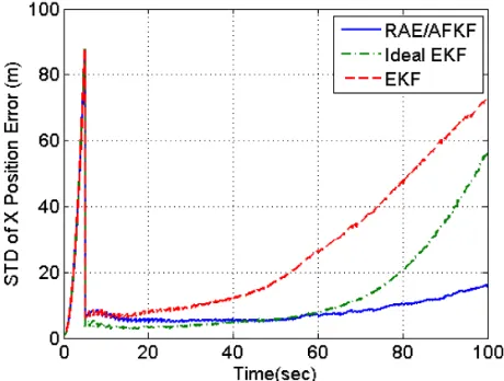
The simulation results described below, show the standard deviations (STD) of the attitude and position errors. Each set of results has been obtained from a batch of 100 MC simulations.
Figs. 8 to 10 illustrate the standard deviation of
in-flight alignment errors. These results explain that
the RAE/AFKF has the superior performance in comparison with the EKF in accuracy and convergence rate. If there is the attitude error requirement of 0.2 degree (1σ), RAE/AFKF relatively satisfies it, but
EKF fails to meet this supposed requirement. As shown in Figs. 8 to 10, the convergence speed of the heading and pitch alignment error is faster than those of bank alignment error. These differences are due to the dissimilar observability of these errors in data fusion process. As shown in Figs. 10, near the
end of flight time, the error curves approach nearly
to the same error value. This approach is due to the
accelerations profile of the interceptor missile.
Fig. 10. STD of heading error based on MC simulation: a) all data and b) zoomed portion Fig. 9. STD of pitch attitude error based on MC simulation: a) all data and b) zoomed portion
The standard deviation of position errors is presented in Figs. 11 to 13. These results show that the RAE/AFKF in comparison with the EKF considerably provides more accurate navigation. Figs. 8 to 13 indicate that until nearly second 50, the performance of IEKF in accuracy and convergence rate is better than that of RAE/AFKF. It means that the accuracy of R-adaptation in the RAE/AFKF
is not sufficient. However, after second 50, the
navigation and alignment accuracy relevant to RAE/ AFKF represent a noticeable preference over IEKF. It implies that the R-adaptation in an adaptive INS/ Radar integrated navigation system is necessary for the navigation and alignment performance improvement against the radar measurements uncertainty, it but is
not sufficient.
From the comparison of EKF and ideal EKF results in Figs. 8 to 13, it can be found that a proper R-adaptation in an adaptive INS/Radar integrated
Fig. 13. STD of Z position error based on MC simulation
Fig. 12. STD of Y position error based on MC simulation Fig. 11. STD of X position error based on MC simulation
navigation system offers an effective tool to
compensate for our insufficient prior information
about the radar measurements accuracies and enhance
the navigation and in-flight alignment performances
as a result of the compensation. Nevertheless, in spite of the true R-adaptation in IEKF, the position error of
navigation system using IEKF in final seconds is more
than that of EKF as seen in Fig. 12. It denotes that the navigation error can be improved by the addition of the other adaption like P-adaption or Q-adaption.
6- Conclusions
In this paper, a new hybrid adaptive filter based on
two concepts of residual-based adaptive estimation
and adaptive fading Kalman filter is proposed for
the inertial navigation system/radio detection and ranging (INS/Radar) integrated navigation system. The Monte Carlo simulation results show that the presented algorithm is effective enough to improve
the in-flight alignment and navigation performance in
the face of the unknown and highly range-dependent accuracy of the tracking radar measurements. The proposed scheme is superior compared to the extended Kalman Filter and offers a possibility
that the in-flight alignment may be achieved within
a relatively short period of time. Also, this new
adaptive filter puts forward a capacity that the
low-cost INS/Radar integration system without aiding global navigation satellite system signals (e.g. Global Positioning System or GPS) can be used throughout the interceptor missile’s mission.
7- Appendix A
measurements are random variables with the standard deviations given by respectively in degrees and meters [14, chapter 10], [15, chapters 4, 6]:
(A.1)
(A.2)
where the free-space, and single-pulse signal-to-noise ratios (S/N) are determined using the radar range equations [14, chapter 3], [17, chapter 1]:
(A.3)
The basic and equivalent glint error standard deviations in angle and range for uniform scattered over a target span L are given by σθG=Lx/3R and σRG=Lr/3, respectively in degrees and meters [17, pages 115-118].
8- Appendix B
The gravity vector in t-frame in terms of the gravity vector in the local level geographic frame, n-frame, is:
(B.1)
where
(B.2)
Cnt is a direction cosine matrix from n-frame to t-frame. The matrix Cnt has been explained in detail in [26, page 37]. By differentiating (B.1) respect to rt, the gravity gradient matrix G is obtained as
(B.3)
where
(B.4)
and for the tactical missiles, i.e. regional range, it can be supposed that
(B.5)
Applying (B.4) to (B.3) gives:
(B.6)
9- References
[1] Titterton, D. H. and Weston, J. L.; “The Alignment of Ship Launched Missile IN Systems,” Inertial
Navigation Sensor Development, IEE Colloquium
on, London, 1989.
[2] Johnson, C.; Ohlmeyer, E. J. and Pepitone, T. R.; “Attitude Dilution of Precision–A New Metric for Observability of in Flight Alignment Errors,” Guidance, Navigation, and Control Conference and
Exhibit, Denver, pp. 2000–2427, 2000.
[3] Ornedo, R. S.; Farnsworth, K. A. and Sandhoo, G. S.; “GPS and Radar Aided Inertial Navigation System for Missile System Applications,” IEEE Position Location and Navigation Symposium, Palm Spring, CA, 1998.
[4] Ohlmeyer, E. J.; Pepitone, T. R. and Hanger, D. B.; “Effect of Trajectory Shaping on Observability of NTW Interceptor In-Flight Alignment Errors,” Dahlgren VA, Naval Surface Warfare Center, 1999. [5] Ohlmeyer, E. J.; Hanger, D. B. and Pepitone, T. R.; “In-Flight Alignment Techniques for Navy Theater Wide Missiles,” Guidance, Navigation and Control
Conference, Montreal, 2001.
[6] Bezick, S. M.; Pue, A. J. and Patzelt, C. M.; “Inertial Navigation for Guided Missile Systems,” Johns Hopkins APL Technical Digest, Applied
Physics Laboratory, Vol. 28, pp. 331–342, 2010. [7] Bar-Itzhack, I. Y. and Porat, B.; “Azimuth Observability Enhancement During Inertial Navigation System In-Flight Alignment,” Journal of
Guidance, Control and Dynamics, Vol. 3, No. 4, pp. 337–344, 1980.
[8] Porat, B. and Bar-Itzhack, I. Y.; “Effect of Acceleration Switching During INS In-Flight Alignment,” Journal of Guidance, Control and
Dynamics, Vol. 4, No. 4, pp. 385–389, 1981.
[9] Bar-Itzhack, I. Y.; “Minimal Order Time Sharing Filters for INS In-Flight Alignment,” Journal of
Guidance, Control and Dynamics, Vol. 5, No. 4, pp. 396–402, 1982.
[11] Anders, J. L.; Buhar, C.; Estrada, V.; Johnson, C. and Ornedo, R. S.; “New Generation GPS and Radar Aided Inertial Navigation System for Ballistic Missile Interceptor,” Procedings of the 60th Annual
Meeting of The Institute of Navigation, Dayton OH, 2004.
[12] Gul, F.; Fang, J. and Khan, S.; “SINS Augmentation by ANS and Secure Radio Positioning System,” 2nd International Conference on Emerging
Technologies (ICET), pp. 278–284, 2006.
[13] Li, S. and Peng, Y.; “Radio Beacons/IMU Integrated Navigation for Mars Entry,” Advances in Space Research, Vol. 47, No. 7, pp. 1265–1279, 2011. [14] Barton, D. K.; “Radar Evaluation Handbook,”
Artech House, Norwood MA, 1991.
[15] Skolnik, M. I.; “Introduction to Radar Systems,”
McGraw Hill, New York, 3rd Edition, 2001.
[16] Mohamed, A. H. and Schwarz, K. P.; “Adaptive Kalman Filtering for INS/GPS,” J. Geodesy, Vol. 73, No. 4, pp. 193–203. 1999.
[17] Barton, D. K.; “Modern Radar System Analysis,”
Artech House, Norwood, MA, 1988.
[18] Ewell, G. W.; Alexander, N. T. and Tomberlin, E. L.; “Investigation of Target Tracking Errors in Monopulse Radars,” Georgia Institute of Technology, Atlanta, Georgia, 1972.
[19] Barton, D. K. and Barton, W. F.; “Modern Radar System Analysis Software and User’s Manual Version 2.0,” Artech House, Norwood MA, 1993.
[20] Jwo, D. J.; Chung, F. C. and Weng, T. P.; “Adaptive Kalman Filter for Navigation Sensor Fusion,” Sensor Fusion and its Applications, Shanghai, InTech, pp. 65–91, 2001.
[21] Hide, C.; Moore, T. and Smith, M.; “Adaptive Kalman Filtering for Low-Cost INS/GPS,” The Journal of Navigation, Vol. 56, Vol. 1, pp. 143–152, 2003.
[22] Xia, Q.; Rao, M.; Ying, Y. and Shen, X.; “Adaptive Fading Kalman Filter with an Application,”
Automatica, Vol. 30, No. 8, pp. 1333–1338, 1994. [23] Jwo, D. J. and Weng, T. P.; “An Adaptive Sensor Fusion Method with Applications in Integrated Navigation,” The Journal of Navigation, Vol. 61, No. 4, pp. 705–721, 2008.
[24] Simon, D.l “Optimal State Estimation,” John
Wiley and Sons, Hoboken, New Jersey, 2006.
[25] Titterton, D. H. and Weston, J. L.; “Strapdown Inertial Navigation Technology,” Peter Peregrinus, London, 1997.
![Fig. 1. Qualitative plot showing relative contributions to the angle tracking error without units [15, page 235]](https://thumb-us.123doks.com/thumbv2/123dok_us/17064.2001721/3.595.323.552.603.756/qualitative-showing-relative-contributions-angle-tracking-error-units.webp)