Design and Implementation of the Low Cost Moving Work Piece
Sorting System Based on LabVIEW
Rajashree R. Kapse
1, Mrs.Warsha Kandalikar
21
M.Tech., Electronics Design & Technology, N.I.E.L.I.T Aurangabad, Maharashtra, India
2 Scientist C, N.I.E.L.I.T Aurangabad, Maharashtra, India
I.
I
NTRODUCTIONThe current sorting techniques use the sorting methods based on the parameters such as color, objects weight, shape and size. The proposed system will utilize a parameter i.e. Size/ height for identifying the various objects. By taking this parameters and using data processing the speed of the sorting process will be increased. Growing technological awareness and skills of the machine users as well as increasing the technical support by sorter manufacturers are the optimistic factors in growing the acceptance of sorting machine.
However, lack of consistent, easy to be maintained and low cost sorting system are giving losses. Thus, there is a need to develop new machines based on reliable sensing and sorting techniques to promote sorting applications.
The technology of sorting different work pieces has a higher demand in industrial production. To reduce the time to production by speeding the sorting technique of raw materials. Currently to automate the sorting process Robots are used which are very costly.
Sorting manually is more time consuming, less accurate and costly. Hence, a low cost system which can sort different objects is required.
Sorting systems remain essential in numerous areas with diverse applications such as in manufacturing industry, libraries, factories, warehouses, pharmacies, supermarkets etc.
The various types of Sorting Methods are as given below:
1. Hand Sorting--Impractical, Time Consuming and Less Efficient 2. Automated Sorting--Reliable, Efficient, Fast and Accurate
Hence a Automated sorting technique is preferred over manual sorting process[2].
Various Parameters that are used to distinguish work pieces are as follows: 1. Colour 2. Shape 3. Size 4. Weight
In our system we will be using the size as a distinguishing parameter to sort various work pieces.
There are various techniques available in the market for sorting purpose namely optical sorting, magnetic sorting, sorting using air gun, electrostatic sorting, acoustic sorting, sorting using conveyor belt.
Of the available techniques we will be using the conveyor based sorting technique in our system.
Abstract:
Sorting is any process of arranging items systematically, arranging them in a sequence ordered by some criterion or grouping items with similar properties. In sensor based sorting the items are singularly detected by a sensor technique and separated by a mechanical, hydraulic or pneumatic process. The sorting techniques are generally applied in the three industries namely mining, recycling and food processing. Advances in sensing and quantifying material surface characteristics in connection with rapid growth in computing and software technology has made it possible to rely on sorting process more and more.Fig. a Sorting using conveyor and controller
II.
System Overview
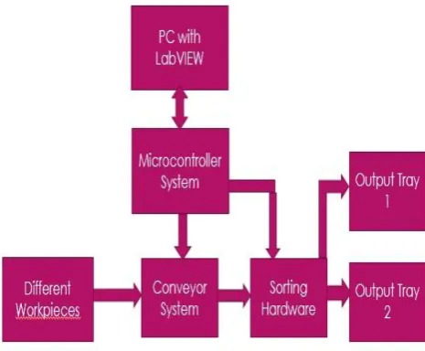
The system consists of a conveyor belt which is rotated using DC motors. Three IR sensors are mounted on the conveyor to determine the size of the work pieces in order to sort them. The IR sensors output is processed by the PIC microcontroller and the objects are moved to output tray 1 or output tray 2 based on the size of the object.
The block diagram of the system is follows:
Fig. b Overall Block Diagram of the system
There will be two types of work pieces with different heights. The conveyor will be rotating continuously with a speed which will be 30rpm in our system. The different work pieces on the conveyor are detected by using the IR Transreceivers which send their output to the microcontroller system. Based on the output which is obtained from the IR transreceivers the size/ height of the object is decided. The sorting hardware will then drop the work pieces based on their size/height into Tray 1 or Tray 2. The conveyor system and the sorting hardware are also controlled and monitored at the remote location using the LabVIEW Software.
III.
Hardware Implementation
The hardware components used for designing the system described in this paper are:
A. PIC Microcontroller 16F877A
operation. It is definitely more useful in a battery powered operation where you want to compare the input battery voltage to a known reference e.g. using the comparator and the internal 0.6V reference. The internal clock is useful for general operation - it can also be set to 31 kHz so consuming less power. The 40 pins make it easier to use the peripherals as the functions are spread out over the pins. This makes it easier to decide what external devices to attach without worrying too much if there are enough pins to do the job. One of the main advantages is that each pin is only shared between two or three functions so it’s easier to decide what the pin function (other devices have up to 5 functions for a pin).
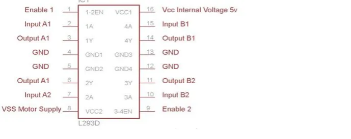
B. L293D Motor Driver IC
L293D is a typical Motor driver or Motor Driver IC which allows DC motor to drive on either direction. L293D is a 16-pin IC which can control a set of two DC motors simultaneously in any direction. It means that you can control two DC motor with a single L293D IC. The l293d can drive small and quiet big motors as well, check the Voltage Specification at the end of this page for more info. It works on the concept of H-bridge. H-bridge is a circuit which allows the voltage to be flown in either direction. As you know voltage need to change its direction for being able to rotate the motor in clockwise or anticlockwise direction, hence H-bridge IC are ideal for driving a DC motor. In a single L293D chip there are two h-Bridge circuit inside the IC which can rotate two dc motor independently. Due its size it is very much used in robotic application for controlling DC motors. Given below is the pin diagram of a L293D motor controller. There are two Enable pins on l293d. Pin 1 and pin 9, for being able to drive the motor, the pin 1 and 9 need to be high. For driving the motor with left H-bridge you need to enable pin 1 to high. And for right H-Bridge you need to make the pin 9 to high. If anyone of the either pin1 or pin9 goes low then the motor in the corresponding section will suspend working. It’s like a switch.
Fig c. Pin Configuration of L293D IC
C. IR Transreceiver
The photo IR sensor uses a photo diode to sense IR Radiations. The output of the infrared sensor circuit is connected to PIC microcontroller pins and the microcontroller will take it as digital input either 0 or 1. According to the o/p of the infrared sensor module, the microcontroller will react by glowing LED. The o/p of the infrared sensor circuit is connected to RA0 pin of the pic microcontroller. It is arranged as i/p with TRISB registers and the o/p of this interfacing will be displayed on LED that is connected across PORTD includes RD5, D6, RD7. Here o/p pins are RB0 and RB1.
D. DC Motor
DC motor has a stationary set of magnets in the stator and an armature with one or more windings of insulated wire wrapped around a soft iron core that concentrates the magnetic field. The windings usually have multiple turns around the core, and in large motors there can be several parallel current paths. The ends of the wire winding are connected to a commutator. The commutator allows each armature coil to be energized in turn and connects the rotating coils with the external power supply through brushes.
RS-232 is a standard communication protocol for linking computer and its peripheral devices to allow serial data exchange. In simple terms RS232 defines the voltage for the path used for data exchange between the devices. It specifies common voltage and signal level, common pin wire configuration and minimum, amount of control signals. As mentioned above this standard was designed with specification for electromechanically teletypewriter and modem system.
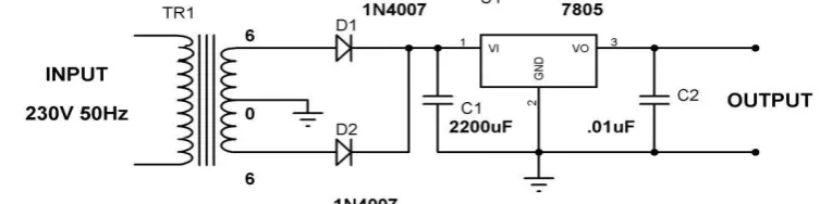
F. Power Supply Unit
We require a 5V supply so we need LM7805 Voltage Regulator IC. 7805 IC Rating: Input voltage range 7V- 35V, Current rating Ic = 1A, Output voltage range
V
Max=5.2V ,V
Min=4.8V. Selecting a suitable transformer is of great importance. The current rating and the secondary voltage of the transformer is a crucial factor. The current rating of the transformer depends upon the current required for the load to be driven. The input voltage to the 7805 IC should be at least 2V greater than the required 2V output, therefore it requires an input voltage at least close to 7V. So I chose a 6-0-6 transformer with current rating 500mA (Since 6*√2 = 8.4V). Its advantage is DC saturation is less as in both cycle diodes conduct.Fig d. Circuit diagram of Power supply unit
IV.
Software Implementation
A. PIC Programming
The PIC microcontrollers is programmed by the embedded C language or assembly language by using
Fig. e Algorithm for PIC 16F877A programming
B. LabVIEW Programming
LabVIEW (Laboratory Virtual Instrument Engineering Workbench) is a highly productive development environment for a visual programming language.
Test point, Measurement Studio, LabVIEW is most widely used due to advantages like parallel programming, code re-use, large available libraries, etc. The algorithm for data processing in LabVIEW is as follows:
Fig. f Algorithm for data processing in LabVIEW
V.
Results and Discussions
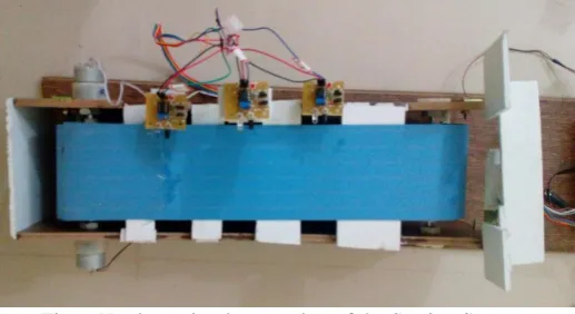
The LabVIEW based Work Piece Sorting system is implemented successfully. The figure below shows the hardware implementation of the system:
Fig. g Hardware implementation of the Sorting System
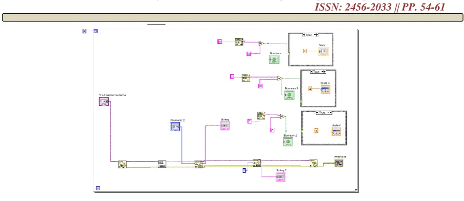
Fig h. Block diagram of system in LabVIEW
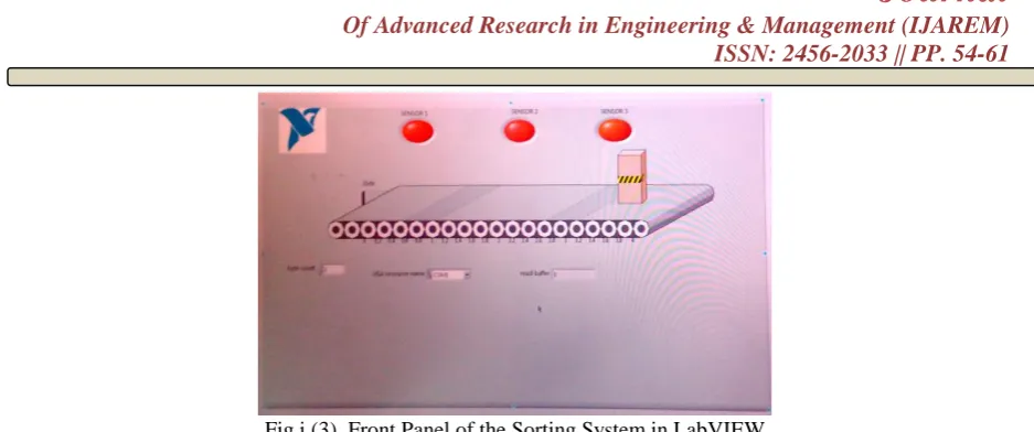
Figure i is the user interface screen designed in LabVIEW software. When the object is placed on the conveyor belt it moves further and initially the sensors indicators are not glowing as shown in the figure i(1).
Fig i (1). Front Panel of the Sorting System in LabVIEW
Fig i (2). Front Panel of the Sorting System in LabVIEW
Fig i (3). Front Panel of the Sorting System in LabVIEW
Hence the design and implementation of the low cost moving work piece sorting system based on LabVIEW is implemented successfully.
References
[1]. Liu Zhenyu , Zhao Bin, Zhu Haibo “Research of Sorting Technology Based on Industrial Robot of
Machine Vision”Computational Intelligence and Design (ISCID), 2012 Fifth International Symposium
[2]. Andres Torres-García, Oscar Rodea-Aragón, Omar Longoria-Gandara “Intelligent Waste Separator” Department of Electronics, Systems and IT (ITESO), Mexico, ISSN 2007-9737
[3]. Swati R. Bhosale Priyanka P. Bandewar Prof. G.B.Firame.” Automatic Box Sorting Machine” IJSRD Vol. 4, Issue 04, 2014
[4]. Nisha , Dinesh Kumar, " VISION ASSISTED PICK AND PLACE ROBOTIC ARM ", Advances in Vision Computing: An International Journal (AVC) Vol.2, No.3, September 2015.
[5]. P. Prashanth.Mr.P. Saravanan.Dr.V.Nandagopa.“Vision Based Object’s Dimension Identification To Sort Exact Material” (IOSR-JEEE) e-ISSN: 2278-1676, Volume 10, Issue 1 Ver. III (Jan – Feb. 2015 [6]. Abahan Sarkar1 , Ram Kumar , A Mohammad “Automatic Counting and Sorting of Balls – An Image
Processing Approach” ISSN: 2231-4946 Volume V, January 2015