Reform the Performance of a Billet Quality by
Reducing its Defects at SAIL-SCL Kerala Limited
Abdul Haseeb NC Alex P Jacob
Department of Mechanical Engineering Department of Mechanical Engineering Saintgits College of Engineering, Kottayam, India Saintgits College of Engineering, Kottayam, India
Arvind Kumar Dibin Vincent
Department of Mechanical Engineering Department of Mechanical Engineering Saintgits College of Engineering, Kottayam, India Saintgits College of Engineering, Kottayam, India
Abstract
The development of continuous casting to produce semi-finished products is now so far advanced that almost any grade of steel can be continuously cast, and in the most appropriate cross section for further shaping. High quality finished products can only be produced by using defect free billet. The removal of defects is either performed selectively by removing the specific defect. Our Project is based on industrial research, refers to the possibility of defining and cataloguing the surface defects specific to the semi-finished products continuously cast, in order to discover the generating source and to take the proper measures to prevent and remedy them where appropriate. We studied the various processes in the industry and done a project to improve the quality of billets, and thereby reducing the major loss of the company. The main problem faced by the industry is the defects caused during casting of the billets. The defectives can only be re-used as scrap, which is the major loss of the industry. Root causes of these defects and solutions recommended are analysed for each case. We suggested a field mixing technology for the mixing of molten metal in correct proportion so that it reduces about 75% of its defects. Also we suggested other methods to improve the quality of billets.
Keywords: Billet, Defect analysis
_______________________________________________________________________________________________________
I.
I
NTRODUCTIONSteel is fundamentally an alloy of iron and carbon; with the carbon content varying up to 1.5%.The carbon is distributed throughout the mass of the metal, not as elemental or free carbon but as a compound (chemical combination) with iron.
If however, the carbon is increased above 1.5%; a stage soon arrives when no more carbon can be contained in the combined state and any excess must be present as free carbon (graphite)-cast iron.
Therefore, for a material to be classed as steel there must be no free carbon in its composition. The importance of carbon in steel lies not in its relative volume but in its remarkable influence on the internal structural changes and mechanical properties which occur when steel is heated and subsequently cooled by various methods.
Carbon steels are predominantly pearlitic in the cast rolled or forged conditions. The constituents of hypoeutectoid steels (steel containing from and below 0.87%carbon) are therefore ferrite and pearlite and hypereutectoid steels from and above 0.87% cementite and pearlite.
II.
I
NDUSTRIAL PROFILESteel industry in India is on an upswing of the strong global and domestic demand. India‟s rapid economic growth and soaring demand by sectors like infrastructure, real estate and automobile, at home and abroad, has put Indian Steel Industry on the global map. According to the latest report by International Iron and Steel Institute (IISI), Indian steel Industry is organized in three categories i.e. the main producer and major producers have integrated iron ore and coal/gas for production of steel. The main producers are TATA steel, SAIL, and RINL while the other major producers are ESSAR, ISPAT and JVSL. The secondary sector is dispersed and consist of (1) Backward linkage from about 120 sponge iron producers that use iron ore and non-coking coal. (2) Approximately 650 mini blast furnaces, electric arc furnaces, induction furnaces and energy optimizing furnaces that use iron ore, sponge iron and melting scrap to produce steel. (3) Forward linkage with 650 re-rollers that roll out semis into finished steel products for consumer use SAIL, the largest public sector corporate entity have invested large amount for up gradation of technology and equipment at their integrated steel plants at Bhilai, Durgapur, Rorkela, Bokaro&Burnpur. SAIL become largest manufactures of steel in India and one of the top 10 steel makers in the world. Large scale modernization and renovation programs have helped SAIL to keep itself abreast of the developments in steel technology and to translate the same to its steel plants so as to move with the time.
The private sector integrated steel plant of the TATA viz, Tata Iron & Steel Ltd at Jamshedpur which was having a capacity of 2.5 million tonnes of saleable steel established a new Hot Strip Mill with a capacity of one million tonnes.
Three major in the secondary sector, who have leaped forward to expand though electric arc furnace route and consolidate their position through technological excellence were ESSAR group viz, ESSAR Gujarat Ltd the largest manufacturers of hot briquetted iron, a substitute for steel scrap in steel making, has its three module plants in Hazira, Gujarat with a capacity with a capacity of 1.75 million tonnes. The Jindal Organization comprises of 4 steel manufacturing companies viz, Jindal Strip Ltd, SAW pipes Ltd, Jindal Iron and Steel Ltd. The Nippon DenroIspat Ltd, the flagship company of the group has their plants near Nagpur manufacturing about 4 tonnes of steel.
Other steel majors who have consolidated postions by putting up new facilities or enhanced such facilities through modernization programs during the eriod were Lloyds steel, Bhushan steel, Bellary steel, Malavika steel, Bhuvalka steel etc.
III.
C
OMPANY PROFILESAIL-SCL KERALA LTD is the only mini steel plant in Kerala. The company was originally promoted in the joint sector between the Kerala Steel Industrial Development Corporation Ltd (KSIDC) and a private entrepreneur in 1969. SCL set up its mini steel plant in 1972 with installed capacity of 3700 tonnes p.a. which was subsequently enhanced to 55000 tonnes p.a. The company commenced commercial production in September 1973.
The steel produced here is strictly conforming to BIS specification falling under Mild, Medium Carbon and Spring Steel qualities and is cast into 100 mm sq. Billets. The billets are further rolled and converted into constructional steel of various sections at rolling mills and marketed by SCL.
SAIL-SCL Kerala LTD is the best option in construction Steel. The company is going ahead with its ambitious expansion program including installation of TMT Rolling Mill. At present SCL is producing 100x100 mm sq. Steel through electric arc furnace route and continuous casting technology. The billets produces in the plant are converted into constructional steel items of different specifications.
Grade BIS License: A.
During refining, samples are analyzed in the laboratory and the process is controlled according to the samples. Steel produces in the plant is every time subjected to the most stringent and uncompromising quality control tests. The company being holder of „A‟ Grade BIS specification, quality control section is equipped with imported Optical Emission Spectrometer capable to analyze 30 elements of steel. Casting is made after analyzing the quality of liquid metal.
TMT Bars: B.
In the mid 1980‟s there was revolution in the steel technology. The invention of thermex and tempcore processes for rolled steel products including long and flats came into practice. Before the mechanical properties of strength, malleability, corrosion resistance etc. used to control by controlling raw material combination of additives like Mn, Si, and Cu etc. This new technology enables to have a product of superior strength and other mechanical properties at lesser cost of production by simply controlling the cooling regime and pattern. „TMT‟ Bars have become a style statement in the construction industry notwithstanding the huge cost benefit and also the superior quality. „TMT‟ bats assume all the more importance considering that most parts of India falls within sesmic zones 3, 4 &5. It would rather be better to term this process also passes off in the market. „An insight into TMT‟ will be beneficial to avoid catastrophic results.
The use of EAF allows steel to be made from a 100% scrap metal feedstock commonly own as cold ferrous feed to emphasize the fact that for an EAF, scrap is a regulated feed material. The primary benefit of this is the large reduction in specific energy (energy per unit weight) required to produce the steel. Another benefit is flexibility while blast furnaces cannot vary their production by much and never stopped, EAF can be rapidly started and is never stopped allowing the steel mill to vary production according to demand.
Government of Kerala has entered into a JV with SAIL. Incorporating the superior technology of SAIL the company has recently entered into the market of the latest quality constructional steel called TMT Bars
3.2.1 Features: 1)
Resists fire
Withstands temperature up to 600°C.
Resist corrosion
The TMT process for superior strength and anticorrosive properties.
Earthquake resistance
The soft ferrite-pearlite core enables the bar to bear dynamic and seismic loading.
Malleability
TMT bars are most preferred because of their flexible nature.
Enables welding
They have fine welding features.
External ribs running across the entire length the TMT bar give superior bonding strength between the bar and the concrete.
Cost-Effective
A high yield strength, stress ration and better elongation value give you great savings.
IV.
H
ISTORY OF THE COMPANYSAIL-SCL KERALA LTD is located in 40 acres of land at Feroke in Kozhikode district Kerala.
Steel Complex Ltd was incorporated on 12th December 1969 with a view to setting off regional imbalance in the supply of essential raw materials, that is steel for construction of building in the state of Kerala. The company was originally promoted In the joint sector by Kerala State Industrial Development Corporation (KSIDC) and the private entrepreneur Mrs.Jifri.
SCL set up its mini steel plant in 1972 with installed capacity of 37000 tonnes. The company commenced commercial production of mild, medium, carbon and spring steel billets of 100mm square in September, 1973 as part of rehabilitation package. KSIDC raised its shareholding in SCL to more than 5% and thus SCL became the subsidy of KSIDC in 1979.
In 1983 SCL undertook expansion scheme by adding the 3rd electric arc furnace by which the production capacity was raised to 55000 tonnes p.a. the operation of the company then improved and SCL earned substantial profits during 1984 to 1986.
In July 1986 SCL took over Malabar steel Re Rolling Mill (p) Ltd. (MSRM) located at Malappuram district. In the year 1994, Government of Kerala took over SCL from KSIDC and the status continues.
History of the Unit with BIFR: A.
Steel Complex Ltd. become a sick industrial company for the first time and made reference to BIFT u/s 12(1) of SICA 1985. At the first hearing held on 5th JANUARY, 1993, IDBI was appointed as Operating Agency (OA) to the rehabilitation prospects of SCL.
SCL submitted a proposal involving takeover of SCL by Government of Kerala from KSIDC and GOK to bring in 7.5 Cr out of which Rs. 3 Cr as additional equity and the balance Rs. 4.5 Cr as loan carrying Interest @ 13.5% p.a. the order came in to effect from 23.05.1995. The Government took over the SCL as per G.O(MS) No.6/94IP, Dated 05.01.1996.
Modified Sanctioned Scheme: B.
The scheme modified 03.01.1997 at the time of review the board declared the scheme as failed and ordered change of management with the view to consider an opportunity for rehabilitating the company as the last chance. Even if IDBI (A) as submitted advertisements for change of management were issued, but there were no response to advertisements within the stipulated period. Finally on 18.11.2003 BIFR issued, considering the sick industrial company viz. Steel Complex Ltd is not likely to make its material all financial obligations and losses within the reasonable time while meeting all its financial obligations and that the company as a result of it is not likely to become viable. In future it is just and equitable that the sick industrial Co M/s Complex Ltd should be wound up in terms of section 20/1 of the act a hearing of the interested personal was fixed on 24.01.2004. After hearing the interested parties and considering the submission made at the hearing and the bench noted that henceforth SBI will be the O>A and IDBI will be discharged of this responsibility. The bench gave the following directions. GOK to give necessary clearance for the companies proposal submitted to them by 31.05.2004.This should be fully tied up rehabilitation package for which SBI has also agreed.
GOK to extend bank guarantee to the SBI by 31.03.2004. if the guarantee is not made available to SBI within the stipulated time frame, the bench will not hesitate in conforming the winding up of the company.
The company will ensure that the interest of workers including revision of wages / payments of workers dues is also including in the rehabilitation package to be submitted by the company.
V.
D
ESCRIPTION OF EQUIPMENTS Furnace:A.
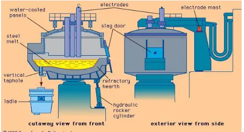
The furnace comprises a cylindrical refractory lined shell with dished bottom and domed roof. The shell is mounted on chassis which also carries a back frame with roof suspension beams, electrode masts, winch units for electrode arms etc. The chassis with the furnace shell and the back frame is carried on two toothed rackers for tilting forward and backward. The separate mounting of the back frame ensures that the torque and stresses set up by roof on electrode movements are transmitted directly to the chassis and have no effect on the frame shell
The furnace is powered by a specially constructed transformer. The electrode movement is controlled electrically by a set of sensitive amplifiers. Tilting of the furnace is carried out hydraulically while the electrode clamps and the slag door are operated pneumatically.
The maximum capacity of furnace after fresh lining is 10 ton. After every taping the capacity will be increased up to 15 ton. Bottom portion of the furnace is lined with DBM ramming material. It contains high percentage of magnesium oxide. It can withstand high temperature. After every tapping some portion of ramming material gets damaged. For repairing the damaged of the bottom ramming material is fettled in the furnace bottom.
The roof rings are supplied so that when one is in operation on the furnace the other may be bricked ready for used. They are of water cooled type and supported by four links attached to the roof lift beams. A platform is provided over the roof brick work to enable the operation to carry out any adjustment necessary to electrode clamps and fit new electrode as required
The roof suspension beam assembly together with the roof is suspended at four points and is lifted by two hydraulic cylinders mounted on the back of the structure. One vertical pivot pin is provided and secured to the chassis. The back structure carrying the roof lifting mechanism rotates about the pivot pin supported on the rollers which moves on a track concentric with its pivot pin. Rotation of the back structure and consequently swinging of the roof is carried out by double acting cylinder.
Electrode arms are of tubular steel sections and carry the water cooled copper tubes to the electrode clamps. The electrode arms are bolted to the cross head which moves on electrode masts mounted on the back structure. The electrode clamps are made of none magnetic heat resisting steel. Water cooled copper inserts are included in the clamps for carrying current to electrode. The clamps are operated by pneumatic cylinder and operating lever.
Transformer: B.
Transformer is of the core type and constructed especially re-inforced windings to withstand heavy current fluctuations in furnace operation. For controlling the input power the arc tapping provisions are made primary windings of the transformer enabling section of ten different voltages ranging from 90 to 250 volt. In the secondary for selecting different voltages in the secondary an off load tap charger is also incorporated in the transformer. The transformer is of oil forced water cooled.
Reactor: C.
The transformer is provided with a series of reactor included in the main tank. The reactor has topping brought on the top of the transformer tank the selection of the reactor tapping corresponds to the reactor tapping corresponding to the reactor tapping corresponding to the voltage tapping are to be made for the stability of the charge material and the fault level of the suppl y system. For overall electrically efficiency minimum amount reactance should be chosen.
Electrode Control: D.
The electrodes are regulated by a motor set comprising three amplidynes mounted on a common bed plate with a driving motor. The amplidynes are arranged to balance the arc voltage against the arc current through suitable increase on the arc voltage. The DC motors of the winch units are specially designed to have low movement of inertia for quick response.
All the three electrodes are simultaneously controlled by a control switch. Each electrode can be individually controlled by hand through a control switch. The electrode control in the second and their furnaces had been changed to static regulations with thyristor control for better and efficient performance of the arc.
Con- Cast Machine: E.
The continuous billet caster is a to strand machine. The two sectors being identical in design and operation except for handling left or right where necessary to facilitate parallel installation.
The main structure of the installation provided support for the raised casting platforms, ladle support, tundish preparation are, and mould and tundish supports. An extension to the structure below the casting floor level provided plat for an emergency ladle positioned to receive the overflow of half metal from the slag box which is positioned on the casting floor. The mould oscillation mechanism is mounted on cross support beams below the casting operation together with alarm and failure indication is provided at the casting floor .Local control of cast at each mould is provided from pendant control box suspended from the back support structure. Access to the main and subsidiary floor level is by stairways having suitable hand rails. An integral steel walled enclosure forms the spray chamber in which the two spray roller aprons are located. A winch assembly is provided for handling the roller aprons.
A straightener assembly mounted at ground level provides the drive and straightening effect for each strand. It also provides the drive for the dummy bar when re stranding the machine
start of casting. Cutting of the strand into billets is affected at the cutting station, the billets are cut into required dimensions with help of portable oxy-acetylene equipment.
Fig. 2: Continuous Casting
The billet pieces are transported along the discharge table until they contact end stops, pushers then move the billets sideways on the cooling beds at the ends of discharge table. A hydraulic power pack provides the pressure to operate the pusher and dummy bar receiver and cylinder.
Control of the discharge sequence is from a discharge control desk mounted on a platform in the discharge area. A multi control center is positioned in the discharge area and these housed in a ventilated enclosure. The enclosure is divided into two rooms, the other rooms housing the hydraulic power pack. A cooling water system supplies water under pressure to the mould and to the spray chamber and discharge table. The water cools the molten metal in the mould and further solidifies the strand in the spray apron during casting process. The water is also used to cool the equipment.
Mould: F.
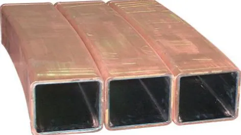
Mould consists of essentially two parts. The mould tube is made up of copper and water jackets. The mould tubes is fixed to the key plate and mounted in the water jacket so that it can freely expand downwards. Water seals are fitted at both ends. An oiler plate is mounted on the top plate, attached to the bottom of water jacket are rolls adjustable and excenters. For each section size, it is recommended to have assembled water jackets and copper tubes ready as spares inorder to reduce mould changing time.
Mould Tubes: G.
They are made of phosphorous deoxidized electrolytic copper with a hardness of 70-90 kg/mm². They are tapered and chromium plated. When mounting the mould tube care must be taken that its position is exactly central in the water jackets inorder to ensure uniform cooling water gap on all four sides. The bottom water seal should not be over tightened to such a degree that it prevents the tube from expanding longitudinally. Prior to casting with a new assembly the mould table and at the top and bottom seals. A slight leakage from the bottom seal is not very serious provided it does not wet the dummy bar head during driving and does not become worse on subsequent casts. No water leakage of the top seal can be tolerated. It is always a good practice to check the prepared mould for leakage immediately prior to every casts.
The size of mould section is 100mm square
Length – 800mm
Taper- 0.9%/m 4m radius
Weight of the mould assembly- 430 kg
Foot Rolls: H.
When using tapered and chromium plated mould tubes the foot rolls prevented the lower part of mould tubes from wearing out excessively and allows on the other hand an easy dummy bar insertion. These rolls must be strictly parallel to mould side wall. The casting radius template can be used for checking these points. The rape seed oil is fed to the various oiler plate outlets by means of an oil-pump through separate feed lines.
Optimum mould cooling is achieved with a water velocity between 5 & 7m/s in the water gap formed by the mould tube and water jacket.
Hydraulic Power Unit: I.
The hydraulic power unit is a package assembly used to provide the power to operate the pusher and dummy bar receiver rams. The package consist of a storage tank which forms the support two electric motors each driving a vane type hydraulic pump. Four solenoid operated selector valves are also mounted on brackets secured to the tank and govern the operation of the pusher and dummy bar receiver rams of each strand.
The tank is floor mounted on corner feet. Fluid level is monitored by a level switch. A minimum quantity of hydraulic fluid must be in the tank before the waters can be started and if the level falls below the minimum during operation the motors are automatically tripped. Slight level gauges are fitted on two sides and combined filler cap and breather is fitted temperature regulator maintains the fluid temperature within a range by governing the flow through water cooler. Fillers are fitted on the suction side of each pump and a shut off walls allows either pump to pressurize one or both strand circuits. A selectable pressure gauge assembly enables either circuits pressure to be indicated
The power pack is connected to the ram by metal pipes and couplings and flexible hoses are connected to the moving parts. The hoses are just wire reinforced and have asbestos as outer covering to protect them from hot metal.
Thermal over load relays protect the electric motors and initiate an arm signal at the main control panel if an over load condition occurs. The alarm is also actuated by the low level float switch in the tank.
Dummy Bar: J.
Dummy bar is of articulated construction consisting of a dummy bar head and a series of links, interconnected by pins and culminating in a tail link. The dummy bar provides the mean of sealing the bottom of the mould at the start of the cast and of withdrawing the strand through spray roller apron to the withdrawal assembly and the dummy bar receiver.
The dummy bar head and link are connected by pins. The pin passes through bushes in the link and is retained in position by spring steel roll pins. The tail link from the end of the dummy bar, the link is drilled to facilitate the attachment of a shackle if required for handling purposes.
Insertion of Dummy Bar: K.
The dummy bar is introduced into the mould tube by means of driving rollers in the pinch roll unit. In the mould the dummy bar head has to be dry otherwise an explosion may occur at the start of cast. Under normal condition pre-heating is not necessary, since the head will still be warm from the previous cast. If the head is wet, it must be dried before entering the mould. The dummy bar head must be introduced 100mm into the mould tube for casting. The sealing method is to be temporarily a length of asbestos chord firmly into the gap between the head and the mould face. The dummy bar head sealing must be covered by nail nips. Dummy bar length is 7440mm and weight is 516kg
Mould Oscillation: L.
The mould is supplied b an oscillation assembly consisting of an oscillation arm actuated by a drive assembly. The mould is located on a secured to a top plate bolted to the oscillation arm. Mould cooling water pipes are connected to the underside of the plate. The mould oscillation is used to prevent the sticking of the solidified crust, the mould oscillate within the direction with a higher speed than casting speed.
Tundish: M.
therefore recommended for this area. In order to eliminate tundish pre heating proprietary lining tiles can be fitted over the work lining.
Fig. 4: Tundish in Continuous Casting
Ladle: N.
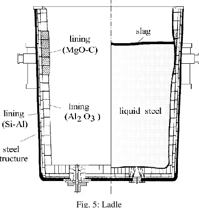
Ladle is a large vessel to hold the liquid metal with a capacity of 12 to 15 ton. It is made with steel and is lined with high alumina refractory bricks. Three layers are provided at the bottom and two layers at the side. It carriers the molten metal from the furnace to the con-cast mould. Ladle is opened by means of hydraulically operated slide gate system which is fitted at the bottom portion of the ladle. The nozzle diameter of the ladle is 24mm.
Fig. 5: Ladle
Ladle Pre Heater: O.
Fig. 6: Ladle Preheater
Sub-Station: P.
They receiving electrical supply at 110KV level from K.S.E.B. They are equipped with two 110KV/11KV transformers of 15MVA and 12.5MVA respectively. The above transformers are arranged for independent working. Secondary supply of 11KV is bought to 11KV bus bar arranged inside the sub-station control room. For the present, all the three furnace load of 5MVA transformer secondary by arrangement of the bus couplers with interlock systems all these load could be changed to the 12.5MVA transformers 11KV secondary bus bar. The different furnace load are head by 11KV 3Phase underground cables they are equipped with all types of circuit breaker including gas circuit breaker, air circuit breaker for the efficient control an protection of the loads on the bus bar.
Pump House: Q.
Steel manufacturing process requires plenty of cooling water for cooling the furnace and con-cast machine. Pump house consist of three separate cooling water pumps for storing furnace cooling, mould cooling and spray cooling water. For pumping cold water from cold sump to various equipment as well as the overhead storage tank 50 HP pump are used. After circulating the spray water through the casting machine, it is collected in the hot water sump near to the con-cast machine. From this it is pumped to the cooling tower. By means of 20 HP turbine pump. This is collected in the cold sump. The mould water pumped from the cold sump is circulated through the mould jacket during casting and is returned back to the hot sump. From this it is pumped to the cooling tower through a 10 HP pump, furnace cooling water is pumped from the furnace and is collected in a tray from where it is collected at the hot sump by gravity flow. It is pumped to the cooling tower with a 10 HP pump. This is collected in the cold sump. This cycle is repeated.
VI.
C
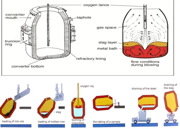
OMMERCIAL STEEL MAKING PROCESSESSThe modern steel making industry is about 150 years old. It began with Bessemer process of steel making. Steel making has been dominated by LD (Linz-Donawitz) process of steel making or in the form of any of its modifications since the 1950‟s. the modified version of LD in the form of combined blowing process or the hybrid process of steel making in any form are the dominant process of steel making currently in use.
The various major types of steel making processes are:
Basic Bessemer process: A.
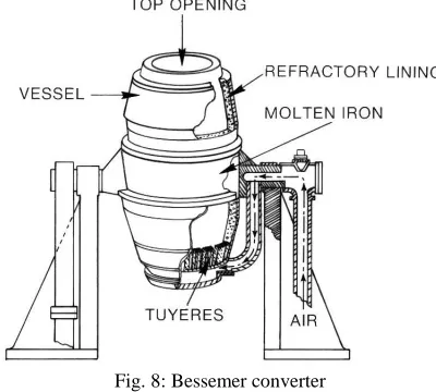
In this process the molten pig iron is held in a vessel with perforated bottom called a converter. Cold air or oxygen enriched blast is forced through the metal refining is completed in about 20 minutes and taking it into account the time for charging, tapping etc. a tap to tap time of about 35 to 40 minutes are required. This is an autogeneous process, i.e. No external heat is needed.
Fig. 8: Bessemer converter
Open Hearth Process: B.
In this process, the furnace is a fairly shallow basic lined vessel. It is heated by either fluid and or gaseous fuels using the heat regeneration principle so as to attain steel making temperatures of about 1600 celsius. In the modern practice charge is a mixture of scrap and molten pig iron.
Fig. 9: Open Hearth Process
Electric Arc Process: C.
Fig. 10: Electric Arc Furnace Cross Section
VII.
E
LECTRIC ARC FURNACE PROCESSElectric arc furnace is used for steel making in SAIL-SCL KERALA. The electric arc furnace looks more like a sauce pan covered from top with an inverted saucer. The electrodes are inserted through the cover from top.
The furnace unit consists of the following parts.
1) Furnace body - the shell, the hearth, the walls, the doors, etc… 2) Gears for furnace body movement.
3) Roof and roof lift arrangement. 4) Electrodes, their holders and support.
5) Electrical equipment‟s - transformer, cables, electrode control, mechanism etc…
The furnace shell is a welded or riveted steel plate construction and has a cylindrical sauce pan like shape. The spherical bottom furnace is the universally accepted model since it is stronger.
The furnace body needs to be tilted through 45 degree on the tapping side and 15 degree on the slagging side. The tilting gear is hydraulic or electric, but usually hydraulic gears are used.
The electrodes are made up of graphite and are capable of carrying current at high density. Their sizes are of 300mm diameter and of length 1-3m. The furnace capacity is about 10-12 tons. The electrode is a costly material and hence its consumption during the operation should be minimum, So as to run the electric arc furnaces, large transformers are required.
VIII.
D
EFECT ANALYSISThe defect can be defined as any deviation from the appearance, form, size, macrostructure or provided in the technical standards. Defects are detected at the billets reception, by checking their surface quality on the inspection beds, or by checking the macrostructure of the test samples. A defect is not always the result of a single case. Often, the defect is the result of multiple interacting causes, depending on a variable number of parameters. Similar defects, as “appearance”, may have one or more different causes, and apparently different defects may have one or more common causes. Therefore, there are often found several defects on the same billet. The defects arising from the steel continuous casting can be classified as follows: surface defects, internal defects, form defects, mechanical defects and deviations from the prescribed chemical composition of steel.
The two primary defects that are commonly seen in billet casting at SAIL-SCL Ltd are surface defects and internal defects.
Surface Defects A.
Surface defects are those defects that are seen on the external surface of the billets. Surface defects can be longitudinal mid face and corner cracks, transverse mid face and corner cracks, and deep oscillation marks. Surface defects in continuous cast products need expensive, time consuming surface grinding, and in severe cases, even downgrading or rejection. Among the surface defects the dominant once are longitudinal casting cracks and lateral casting cracks.
Longitudinal Casting Cracks 1)
These cracks form at the initial moment of crystallization. They usually appear at corners of faces of billets. It is because the outer crest of billets which is uneven in thickness and detached from the mould owing to shrinkage, fails to withstand the ferrostatic pressure of molten metal. They form in the direction of extracting the strand from the mould.
Pin Holes: 2)
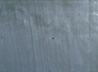
Pin holes are observed often for semi-killed steels cast with casting powder. It can give a place to defects in the final product if there is an important number in a small area or if they penetrate deep in the billet.
Fig. 11: Pin holes on the surface of a billet observed by magnifying glass
Pinholes, often referred to as surface blow holes, occur sporadically an over large areas can affect all cast piece areas. In many cases, they only become visible after mechanical processing, but they are always visible to naked eye. They are primarily found on the outside of the cast piece or just below the surface of cast pieces made of cast iron with lamellar graphite, nodular graphite and vermicular graphite and in malleable iron casting and steel casting. Pin holes can appear in various forms, from spherical blisters with a bare metal surface or covered with small graphite skins to large, irregularly shaped cavities accompanied by slags or occurrences of oxidation.
Star Crack: 3)
Fig. 12: Star crack
They are very fine, being visible only on scale free surfaces. For removing the defect, the surfaces are locally grinded (if the cracks are not too deep).The causes that give rise to star cracks are the intense local cooling, which induce local tensions, and the presence of copper at the austenitic grain limit.
Transverse Crack 4)
Transverse cracks, although not always detect in the inspection of billets, may also give place to serious defect in the rolled products andare rarely seen in round profiles they appear due to the tensions on the longitudinal direction of strand. If they are not deep, they are grinded (deviations within the permissible prescribed limits for diameter and ovality).
Transverse Depressions 5)
Fig. 14: Transverse Depression
The transverse depressions are formed in the transverse direction and may cyclically occur in relation to the strand length. The width of the depressions may cover some oscillation marks, and the depth can reach several mm. The peritectic steels with low Carbon percent and high percent of Manganese and the stainless steels are sensitive to the formation of this type of defect, due to the much larger contractions occurred during solidification.
The depressions precede the occurrence of the longitudinal shrinkage cracks and the marginal internal cracks (subcutaneous). The material that presents this type of defect is locally and cyclically grinded, to check the presence of subcutaneous fissures. The macro sample is taken.
Internal Defects: B.
Internal defects are those defects which normally occur inside the surface of the billet. These defects occur mainly due to the varying metal composition and also due to improper mixing of molten metal.
Intercrystalline Cracks 1)
Fig. 15: Intercrystalline Crack
Cr-Ni steels with nickel greater than 4% of its composition and other complex alloyed steels are especially prone to form intercrystalline cracks. These cracks are formed due to internal stress appearing in billet due to different rates of cooling of outer and deeper layers, inhomogeneity in metal composition resulting in that the metal in dendritic axis and interdendritic spaces pass through the critical point at different time, sulphide and aluminium nitride which segregate at grain boundaries weaken the cleavage between the grains.
Formation of cracks begins from the end of crystallization and may proceed for a rather long time during storage of billets in cold state. These cracks at the axis of billet can cause lamination in the fracture of alloy steel. Intercrystalline spider shaped cracks at the billet axis can be welded by rolling with high reduction ratio.
Internal Blow Holes: 2)
This defect is due to the high gas content or improper de-oxidation of metal before tapping, a moist launder, and ladle or bottom plates. This can be seen as spongy structure in the cross section. Blowholes are cavities in the outer surface or in the subcutaneous zone of the billet, located at few tenths of millimetres from the stand surface. They have a diameter of 3 mm and a length (depth) that can reach up to 25 mm. Usually they contain CO, relatively low H2 and Ar, and they are often associated with inclusions.
Flakes: 3)
Appear in billets during cooling, as the volumes of internal voids diminish upon thermo-mechanical treatment of billet, the pressure of molecular hydrogen increases. And when, this exceeds the strength of steel, the metal fractures internally and forms flakes. They are also promoted by internal stresses caused by structural transformations in a chemically heterogeneous billet or fast cooling of billet. Flakes can cause sudden failures of parts operating under variable loads.
Shrinkage Porosity: 4)
Fig. 17: Different Pores Seen on Billet
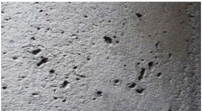
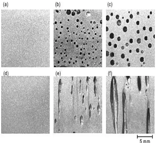
Shrinkage defects occur when feed metal is notavailable to compensate for shrinkage as the metal solidifies. Shrinkage defects can be split into two different types: open shrinkage defects and closed shrinkage defects. Open shrinkage defects are open to the atmosphere, therefore as the shrinkage cavity forms air compensates. There are two types of open air defects: pipes and caved surfaces. Pipes form at the surface of the casting and burrow into the casting, while caved surfaces are shallow cavities that form across the surface of the casting. Closed shrinkage defects, also known as shrinkage porosity, are defects that form within the casting. Isolated pools of liquid form inside solidified metal, and they are called hot spots. The shrinkage defect usually forms at the top of the hot spots. They require a nucleation point, so impurities and dissolved gas caninduce closed shrinkage defects. The defects are broken up into macroporosity and microporosity (or microshrinkage), where macroporosity can be seen by the naked eye and microporosity cannot.
Shrinkage porosity is mainly observed in high carbon alloy steel and steels of high viscosity. Temperature and fluidity of metal diminish during the cost of teeming.Shrinkage porosity represents a gap of material, visible in the cross section at the end of a bar. It can be removed by cutting the end of the bar, and the defective portion is rejected. The causes that produce this defect are high casting temperature, high extraction speed and intense secondary cooling.
IX.
R
OOT CAUSE ANALYSIS Longitudinal Casting Cracks:A.
Pinholes: B.
Formation of pinholes is mostly related to evolution of gases resulting from casting powder decomposition during casting and can be enhanced by high oxygen activity in the liquid steel. Normal figures for lubrication rate are 20 to 30 gm/min, depending on powder properties, billet size and casting speed.
Star Crack: C.
The causes that give rise to star cracks are the intenselocal cooling, which induce local tensions, and the presence of copper at the austenitic grain limit. They appear at 500 – 600 ºC due to thermal stresses if the ductility of material is too low.
Transverse Crack: D.
Transverse crack can be caused by the thermal stresses due to the uneven solidification of the crust and the additional stress due to turbulent flow in the meniscus, also due to meniscus level variation andpresence of segregations which cool more slowly and weaken the austenitic grain boundaries. Friction of the strand in the mould at higher casting speeds.They also appear when the melt flow between the mould wall and crust decreases. The edge friction increases with the viscosity of the powder used) or in the cylinder segments.Transverse cracks can form in the mould or during strengthening. When they are located in any corner, they are likely to be formed due to tensile effort related to sticking, this can be worsen by deep oscillation marks When the cracks are present only in the corner belonging to inner radius, they could be formed by tensile efforts during strengthening. This is common when corner temperature is within low ductility range.
Transverse Depressions: E.
The transverse depressions can be caused by the steel level fluctuation in the mould, by the too large quantity of melted flux, located in the space between the mould wall and the strand, and by the turbulent steel flow at the sub-meniscus level.
Intercrystalline Cracks: F.
Intercrystalline cracks form due to the internal stresses appearing in billet due to different rates of cooling of outer and d eeper layers. In addition to this inhomogeneity in metal composition resulting in that the metal in dendritic axes and interdendritic spaces pass through the critical points at different time also result in these kind of cracks. Sulphide and nitride which segregate at grain boundaries weaken the cleavage between the grains.
Internal Blow Holes: G.
The major reason for internal blow holes are insufficient deoxidation of steel, Moisture present in the casting powder.Also by increasing the quality of the casting powder and quantity and uniformity of its distribution. The variation of the steel level in the mould and the existence of moisture in the refractory lining of the tundishcan cause internal blow holes. The presence of argon entered in the mould during the injection of argon for filling the nozzle may also result in internal blow holes.
Shrinkage Porosity: H.
The density of a metal in molten state is less than its density in the solid state. Therefore, when a metal changes phase from the molten state to the solid state, it always shrinks in size. This shrinkage takes place when the casting is solidifying inside a mould. At the centre of thick sections of a casting, this shrinkage can end up as many small voids known as „shrinkage porosity‟. If the shrinkage porosity is small in diameter and confined to the very centre of thick sections it will usually cause no problems. However, if it is larger in size, or joined together, it can severely weaken a casting. It is also a particular problem for castings which need to be gas tight or watertight‟.
X.
P
REVENTION METHODS Longitudinal Cracks:A.
These cracks can be minimized by supplying rigid stream of metal strictly at the axis of billets, by increasing the perimeter of the mould. They can be also reduced by retarding the teeming rate as well as by enhancing the viscosity of molten metal by changing its metal composition. Another effective method is to use square mould with concave surface.S. KUMAR et.al [2]
Pinholes: B.
To minimize pinhole formation it is important not only to check if lubrication rate is within the usual range, but also verify if the powder distribution in the transverse section is homogeneous. Good distribution of casting powder is very important and to avoid excessive use of lubrication in corners. Also proper mixing of molten metal is required to avoid pinholes from casting. DINESH DEKATE et.al [9]
Star Crack: C.
and the mould we can reduce star cracks to an extent.The cooling of the strand with a moderate intensity when it leaves the mould, to avoid the increase of the thermal stress and the development of cracks.ERIKA MONICA POPA et.al [7]
Transverse Crack: D.
A sound approach to solve the problem is to set proper secondary cooling to avoid the dangerous temperature range in the corners during strengthening. Air-water mist cooling provides more uniform cooling in both casting and transverse directions,and hence avoids cracks by minimizing the localized temperature fluctuations caused by the undercooling and overcooling associated with water droplet spray jets.ERIKA MONICA POPA et.al [7], DINESH DEKATE et.al [9]
Transverse Depressions: E.
They can be remedied by controlling the steel level fluctuation in the mould, by using a mould with parabolic taper, by using a powder lubricant with suitable viscosity and melting rate, by minimizing the turbulence and surface agitation, optimizing the position of the input nozzle and its support.However, each oscillation cycle createsa transverse depression in the solidifying shell at the meniscus, called an oscillation mark. Pressure from interaction with the flux rim at the meniscus can deepen these marks. Unsteady level fluctuations and surface waves due to turbulence can disturb formation of these marks, creating surface defects, such as ripples or depressions in the final product.ERIKA MONICA POPA et.al [7]
Intercrystalline Cracks: F.
These types of cracks can be minimized by proper mixing of the molten metal, lowering the sulphur level, by applying high reduction ratio and by heating the top of the moulds so as to minimize the rate of heat transfer and improve the supply of metal to the axial portion of the billet. Proper mixing of molten metal is required to avoid these kinds of cracks. Transferhot billets soon after complete solidification to soaking pits and control the temperature of molten metal and rate of teeming so as to ensure good filling of shrinkage voids. LIFENG ZHANG et.al [1]
Internal Blow Holes: G.
Internal Blow holes can be prevented by following methods
1) Sufficient de-oxidation of steel by using dry materials and additives. 2) Protection of ladle and tundish.
3) use of dry casting powder (and preheated, if possible).
4) Possibly choosing a casting powder compatible with the steel grade.
5) Temperature and casting speed(and, of course, a good correlation between the casting power quantity and the casting speed).
6) Controlling the steel level fluctuations in the mould, to prevent the steel to flow over the casting powder and to embed it, controlling the nozzle immersion depth, use of nozzles free of defects.
7) Avoiding the high casting temperatures.
8) Maintaining the argon debit below the critical value, to avoid the capture of argon bubbles by the meniscus and the development of slag foaming around the nozzle.
BRIAN G. THOMAS et.al [8], S. Kumar et.al [2]
Shrinkage Porosity: H.
The general technique for eliminating shrinkageporosity is to ensure that liquid metal under pressure continues to flow into the voids as they form. The mold walls should be routinely tapered to match the steel shrinkage in order to minimize air gap formation. Proper mixing of molten metal is recommended to avoid Shrinkage defects.Maintaining the change in temperature within the established limits anda good correlation between the casting speeds and cooling regimes shrinkage porosity can be eliminated. And also reduction of the casting speed, reduction of thecooling intensity, maintaining the water flow at theestablished minimum limit can reduce shrinkage porosity.RAJESH RAJKOLHE et.al [5]
Out of the major defects we analysed in our project, the main reason for the formation of defects in the continuous cast billet at SAIL-SCL KERALA Ltd is due to the improper mixing of molten metal.
XI.
F
IXED MIXERIn SAIL-SCL KERALA Ltd there is no adequate means for mixing of molten metal. Due to the arcing of electrodes in the furnace,pulses are generated inside the furnace. These pulses cause a slight motion to the molten metal.
For providing an additional mixing to the molten metal we suggested the idea about field mixing. If we can supply a three phase or two phase frequency converter, a rotating magnetic field can be generated, whose variation inside the steel produces eddy current. These current interacting with the magnetic field generates a force. This will result in the occurrence of a torque that induces the molten metal to rotate.
Fig. 18: Design of Field Mixer
XII.
C
ONCLUSIONSThe requirement of steel is increasing rapidly in every corner of engineering work. So it is necessary to make improvements in the steel we are using. In our project work different casting defects are analysed. By referring different journal papers causes and their remedies are listed for each defect.These will help the qualitycontrol department of SAIL-SCL KERALA Ltd for the analysis of casting defectsand also improve the productivity and yield of casting. So by adopting these techniques, the SAIL-SCL KERAL Ltd can produce better quality billets.
A
CKNOWLEDGMENTThe authors would like to acknowledge the support of Mechanical Engineering Department of Saintgits College of Engineering for conducting the present investigation.
R
EFERENCES[1] Lifeng Zhang (Dr.), Brian G. Thomas (Prof.) “Inclusions In Continuous Casting Of Steel” XXIV National Steelmaking Symposium, Morelia, Mich, Mexico, 26-28, Nov.2003, pp. 138-183.
[2] S. Kumar, I.V. Samarasekera, J.K. Brimacombe, “Mould thermal response and formation of defects in the continuous casting of steel billets––laps and bleeds” Iron and Steelmaker (1997) 53–69
[3] S. Kumar, B.N. Walker, I.V. Samarasekera, J.K. Brimacombe “Chaos at the meniscus––the genesis of defects in continuously cast steel billets” 13th PTD Conference Proceeding, 1993, pp. 119–141
[4] Alexander V. Lotov, George K. Kamenev, Vadim E. Berezkin , KaisaMiettinen“Optimal control of cooling process in continuous casting of steel using a visualization-based multi-criteria approach” Applied Mathematical Modelling 29 (2005) 653–672
[5] Rajesh Rajkolhe, J. G. Khan “Defects, Causes and Their Remedies in Casting Process” International Journal of Research in Advent Technology, Vol.2, No.3, March 2014 E-ISSN: 2321-9637
[6] Dr D.N.Shivappa1, Mr Rohit, Mr.Abhijit Bhattacharya “Analysis of Casting Defects and Identification of Remedial Measures” International Journal of Engineering Inventions ISSN: 2278-7461, Volume 1, Issue 6 (October2012) PP: 01-05
[7] Erika Monica POPA, Imre KISS "Assessment of surface defects in continuously cast steel” ACTAQ TECHNICA CORVINIENSIS-Bulletin of Engineering Tome IV (2011). ISSN 2067- 3809
[8] Brian G. Thomas “Modeling of Continuous-Casting Defects Related to Mold Fluid Flow” 3rd Internat. Congress on Science & Technology of Steelmaking, Charlotte, NC, May 9-12, AIST, Warrendale, PA, 2005, pp. 847-861.