*Corresponding author
Effect of blade profile on the performance characteristics of axial
compressor in design condition
SarallahAbbasi a,* and AliJoodaki b
a School of Mechanical Engineering, Arak University of Technology, Arak, 38181-41167, Iran b Faculty of Engineering, University of Ayatollah Alozma Boroujerdi, Boroujerd, Iran.
Article info:
Type: Research
Abstract
The choice of geometrical shape of the blades has a considerable effect on aerodynamic performance and flow characteristics in axial compressors. In this paper, the effects of the blades shape on the aerodynamic design characteristics are investigated based on Streamline Curvature Method (SCM). Initially, the Streamline Curvature Method (SCM) is used for designing a two-stage axial compressor. Comparing the current results with experimental ones indicates good agreement. The first stage of the axial compressor is selected with three different blade profiles. The first case (case I) has the polynomial camber with naca thickness distribution series 6. The second case (case II) has the standard naca profile series 6 and the third case (case III) has the modified standard naca profile series 4. Results reveal that using the standard airfoils in the stators leads to improved flow conditions such as loss coefficient and pressure ratio. On the contrary, this profile selection may cause an increase in the stagger angle that is not favorable. Aerodynamic Design with a polynomial camber line in the rotor demonstrates a better aerodynamic behavior in loss coefficient, pressure ratio and diffusion factor. Whilst the use of such a camber line in the stator leads to the formation of less favorable aerodynamics conditions in comparison to the standard airfoil.
Received: 16/12/2017 Revised: 29/10/2018 Accepted: 01/11/2018 Online: 04/11/2018
Keywords: Axial compressor, Streamline curvature method,
Blade geometry, Design condition.
Nomenclature
C Blade chord (m) z, r axial and radial (including radius)
direction, respectively
cli section design lift coefficient s Entropy (N.mlkg.K)
Fn Normal blade force (N/kg) T Static temperature (K)
h Blade height (m) VM Meridional velocity (mis)
ho Stagnation enthalpy (N.ml kg) Vɵ Swirl velocity (mis)
I Distortion index x % abscissa. Of point on the surface of a
symmetrical section or a chord line
i Incidence angle ( deg) y Ordinate of point on the surface of a wing
section
LE Leading edge z Axial length (m)
l Quasi-orthogonal direction p Chordwise position of maximum ordinate
m Meridional direction ɵ Blade camber angle (Rad)
m Maximum ordinate of mean line expressed as fraction of chord
σ Blade solidity
N Rotational speed (r/min) Φ Streamline slope (deg) Po Stagnation pressure (Pa) ω Loss coefficient
1. Introduction
In recent years, applying gas turbines of an axial type has been expanded due to proper efficiency in high revolution and high mass flow rate. In the current world of energy crisis, gas turbines also face the challenge of increasing energy costs. Therefore, one of the areas of research is to focus on reducing energy consumption in these systems. It is clear that energy consumption is reduced by enhancing the efficiency of the compressor and its better performance [1]. One of the most crucial parts of these systems is the axial flow compressor. The proper design of the compressor blades which is associated with correctly implementing the design steps, is effective on both performance characteristics and overall energy consumption of the gas turbines. Moreover, producing further loss in compressor is indicative of weak compressor design [2]. Sen et al. showed that flow structure in the compressor improved when the aerodynamic, performance and structural requirements were satisfied [3]. Hustrulid et al. explained that poor aerodynamic design was the main reason of the undesirable performance and reduced efficiency in the axial fans [4]. By assuming the accuracy of all design steps, optimal performance of the axial compressor will be met, if the blade shape is selected properly. To achieve small size and weight in modern gas turbines, both high aerodynamic loading and Mach number on the blades are inevitable and lead to the complexity of the blade shapes. Several experimental studies have been conducted on applying different geometric shapes of turbomachinery in an axial cascade [5-7]. However, the obtained results have not
reported the complexity of the highly three-dimensional flow in the advanced transonic compressor (especially, in both high loading and Mach number). Therefore, more studies are required to investigate three-dimensional flow in the axial compressor with different blade shapes.
In experimental tests, limitations of instrument and cost cause this method to be difficult for investigation. Many advances have been made in the numerical methods using computational fluid dynamics methods [1-3], however, applying the CFD analysis with solving complete flow and energy equations in a very complex geometry like compressor or fan takes more time and is not reasonable. Due to difficulties in both experimental and CFD analyses, different methods with some simplifications are presented for design purpose and flow analysis. In this respect, most of researchers and designers prefer working on meridional plane of turbomachine [8]. Governing equations on hub to tip through flow surface (referred to as S2-surface) can be solved on meridional plane using streamline curvature method (SCM). A good review on different design methods can be found in Lakshminarayana [8]. Final results are comparable with those obtained through CFD methods, which usually consume extreme time and expense [9]. This method has been employed by Hearsy [10], Pachidis et al. [9], Templalexis et al. [11], Hu et al. [12] and Gong et al. [13] to design and analyze different kinds of turbomachine.
2.Streamline curvature method and verification
2.1. Streamline curvature method
Streamline curvature method (SCM) is widely used for quasi-three-dimensional design of an axial compressor blade. SCM is utilized primarily for an inviscid flow. In fact, it offers a flexible method of determining an Euler solution of axisymmetric flow through a turbomachine. Then, a discrete increase of entropy, which is determined from loss correlations, is imposed to represent the viscous effects. It is clear that the accuracy of the results highly depends on the validity of loss correlations. Governing main system of equations consists of linear momentum and continuity equations. Then, combined with the thermodynamic equation of state, the resultant equation is mapped into the meridional plane of the flow passage. Consequently, based on the assumptions made in this method and mapping into the meridional plane, the final form of the governing equation can be presented as Eq. (1). Fundamentals of this method include its precise concept and details of the governing equations; and necessary correlations can be found in Hearsey [10].
(1) 𝑉𝑚
𝑑𝑉𝑚
𝑑𝑙 = 𝑠𝑖𝑛(𝜑 − 𝛾) [𝑉𝑚 𝜕𝑉𝑚
𝜕𝑚 − 𝐹𝑚]
+ 𝑐𝑜𝑠( 𝜑
− 𝛾) [𝑉𝑚 2
𝑟𝑐
− 𝐹𝑛] + 𝑑ℎ0
𝑑𝑙
− 𝑇𝑑𝑠 𝑑𝑙−
𝑉𝜃 𝑟
𝑑(𝑟𝑉𝜃) 𝑑𝑙
Where 𝑉𝑚 and 𝑉𝜃are respectively meridional
and swirl velocity, Fm and Fn are blade forces
(meridional blade force and normal blade force), 𝑙 and 𝑚 are respectively quasi-orthogonal and meridional direction, 𝑟 and 𝑟𝑐 is
the radial direction and streamline curvature radius, ho is stagnation enthalpy, s is entropy
and T is static temperature. 𝜑 and 𝛾 are deflection angle and sweep angle.
Eq. (1) is solved as an ordinary first order differential equation. In this respect, a computerized program is developed which consisted of two main parts. The first part is mainly used for obtaining three dimensional geometry of blades and the next part produced performance curve of turbomachines. The computerized code utilizes empirical correlations for calculating various kinds of loss accompanied by axial compressors. Obviously, the reliability of the final results highly depends on the degree of precision of these correlations. In order to implement viscous effects in governing equations, empirical correlations must be used for loss coefficient and incidence and deviation angles. Loss coefficient is divided into four parts: profile loss, shock loss, secondary flow loss and tip clearance loss. In the present research, profile loss coefficient is calculated from Koch and Smith’s correlation [14], shock loss coefficient from Swan’s correlation [15], secondary flow loss coefficient from Griepentrog’s correlation [16] and tip clearance loss coefficient from Storer and Cumpsty’s correlation [17]. These coefficients are based on minimum loss coefficient (design condition). Other parameters computed via empirical correlations are incidence and deviation angles. Popular correlations of Lieblein [18] are used for obtaining these parameters [19].
2.2. Experimental validation
illustrated in Fig. 1. Overall characteristics of this compressor are also shown in Table 1.
Fig. 1. The computational grids in the meridian plane.
Table 1. Overall characteristics of Urasek’s two-stage compressor (Urasek et al., 1979).
Inlet total pressure (kpa) 101.325
Inlet total temperature (k) 288
Mass flow rate (kg/s) 33.2
Rotational velocity (r/min) 16042
Overall pressure ratio 2.4
Number of stages 2
First rotor aspect ratio 1.56
Aerodynamic efficiency (%) 84.9
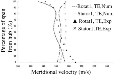
The meridional velocity distribution (as the most important result of SCM) at the trailing edge of the first rotor and stator is presented in Fig. 2(a). The radial distribution of the pressure ratio in the rotor and stator of first stage is depicted in Fig. 2(b). It can be seen that the general tendency of the results are close to the experimental data. It is clear that the experimental and numerical results are in good agreement.
3. The geometrical shape of the blades
Changing the geometric shape of the blade can be achieved by altering the camber line or blade thickness distribution. Different blade profiles with different camber line or different thickness distributions can be used in the design process of the axial compressor by SCM. The most
common blade profile used for axial compressors is standard naca airfoil series. Different shapes such as polynomial camber, standard naca camber series 6 and standard naca camber series 4 can be used as camber line. Also, the most common thickness distributions for blade profile are naca thickness distributions series 4 and 6. In the present study, three types of geometric profile shapes for compressor blades have been considered. The first case (case I) has the polynomial camber with naca thickness distribution series 6. The second case (case II) has the standard naca profile series 6 and the third case (case III) has the modified standard naca profile series 4. Details of these profiles have been discussed as follows. Accordingly, in design condition, the effect of blade profile on performance characteristics and details of flow field in the axial compressor are investigated.
Fig. 2(a). Experimental validation of meridional velocity at design condition.
Fig. 2(b). Experimental validation of pressure ratio at design condition.
Axial position (m)
R
ad
ial
p
o
sitio
n
(
m
)
Meridional velocity (m/s)
---Rotat1, TE,Num
―Stator1, TE,Num ▲ Rotat1, TE,Exp
× Stator1,TE,Exp
P
er
ce
n
tag
e
o
f
sp
an
fr
o
m
h
u
b
(
%)
Pressure ratio
P
er
ce
n
tag
e
o
f
sp
an
fr
o
m
h
u
b
(
%)
---Rotator1, TE,Num
―Stator1, TE,Num ▲Rotator1,TE,Exp
Case I: polynomial camber line and naca thickness distribution series 6
To create the blades with polynomial camber and naca thickness distribution of standard series 6, firstly the absolute or relative angles are calculated in the SCM. Then, using the empirical relations along the blade, the incidence and deviation angles are derived and the blade angles in each quasi-orthogonal line are recognized. In the first case (case I), a parabolic curve is fitted between the two quasi-orthogonal lines. Then, Constants of these curves have been obtained [21]. By connecting these parabolic curves along a compressor blade, a polygonal camber line is created. Consequently, 2D profile shape in each streamline is achieved by applying the naca airfoil series 6 distribution with a maximum thickness of 50%.
Case II: standard naca airfoil series 6
The standard naca airfoil series 6 is quite suitable for supersonic flow in the compressors and is designed to keep the laminar flow in the most part of the chord. In the second case (case II), the naca standard camber series 6 with uniform loading (a=1) is employed according to Eq. (2) [22]. Similar to the previous case, the thickness distribution of naca airfoil series 6 with maximum thickness in 50% of chord is used.
𝑦
𝑐
= −
𝐶𝑙𝑖
4𝜋
[(1 −
𝑥
𝑐
) ln (1 −
𝑥 𝑐
) +
𝑥𝑐
ln (
𝑥 𝑐)]
(2)
Case III: modified standard naca airfoil series 4
These airfoils have the naca camber line series 4, but its thickness distribution is determined by changing the maximum thickness position. Both camber line relation and thickness distribution are presented in eEqs. (3 and 4) [22].
𝑦
𝑐
=
𝑀
𝑃2
[2𝑃 (
𝑥
𝑐
) − (
𝑥 𝑐
)
2
]
(
𝑥𝑐
) ≤
𝑃
𝑦𝑐
=
𝑀
(1−𝑃)2
[1 − 2𝑃 + 2𝑃 (
𝑥 𝑐
) −
(
𝑥 𝑐)
2
]
(
𝑥𝑐
) > 𝑃
(3)
𝑦𝑡
𝑐
= 5
𝑡 𝑐
[𝑎
0√(
𝑥
𝑐
) + 𝑎
1(
𝑥 𝑐) +
𝑎
2(
𝑥 𝑐)
2
+ 𝑎
3(
𝑥 𝑐)
3
] (
𝑥𝑐
) ≤
𝑇 (11)
𝑦𝑡
𝑐
= 5
𝑡
𝑐
[0.002 + 𝑑
1(1 −
𝑥 𝑐
) +
𝑑
2(1 −
𝑥𝑐
)
2+ 𝑑
3(1 −
𝑥 𝑐
)
3
]
(
𝑥𝑐
) > 𝑇
(4)
In the above relations ai and di are the empirical
constants and P and T are the locations of the maximum camber and thickness in tenths of chord.
4.Results and discussion
To investigate the effects of blade profile in aerodynamic design of an axial compressor, the first stage of the compressor is redesigned by using three types of geometric profile shapes. Other required parameters for aerodynamic design by SCM such as inlet conditions, load coefficient, meridional geometry, maximum thickness and number of blade are considered the same in all cases. In this section, the results of the first stage of designing the compressor in all considered cases for blade profile are discussed.
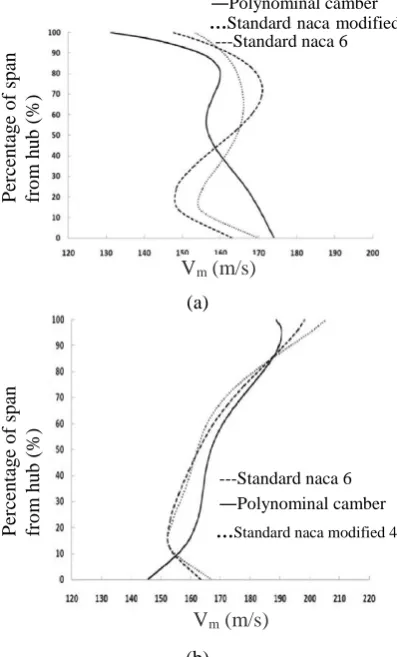
the standard airfoil (in cases II, III) leads to higher meridional velocity at the tip and lower in the hub of the compressor (Fig. 3(a)). Referring to Fig. 4(a), it can be clearly seen that the losses of the polynomial camber (case I) in the hub is less than other cases. Whereas, at the tip of the blade, the total losses in all cases are the same. The radial distribution of loss coefficient in the stator is shown in Fig. 4(b). Unlike the rotor, the standard naca airfoil series 6 (case II) has a much lower loss than airfoil with the polynomial camber (case I).It seems that the use of this kind of airfoil in the stators is more desirable. Also, the modified standard naca airfoil series 4 (case III) has a much lower loss coefficient in the hub than polynomial camber (case I). The loss results of two cases (cases I, III) are coincided at the tip, that is, this profile shape of airfoil does not have much advantage.
(a)
(b)
Fig. 3. Distribution of the meridional velocities on the first stage on the trailing edge (a)rotor (b) stator.
(a)
(b)
Fig. 4. Distribution of the loss coefficient on the first stage (a) rotor (b) stator.
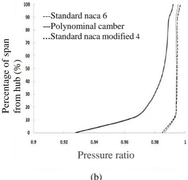
Based on the results presented in Fig. 5, it can be deduced that the radial distribution of the pressure ratio is different in three cases. By regarding the same considered loading coefficient for all cases, this discrepancy is due to different loss produced in design process. The lower losses in the rotor with polynomial camber (case I) result in higher pressure ratio and further losses in the stator result in lower pressure ratio. This shows the advantage of using standard airfoil in the stator.
Diffusion factor is one of the most important parameters in the design of the compressor which is usually recommended not to exceed 55%. As can be depicted from Fig. 6(a), the distribution of diffusion factor along the blade span in the rotor blade with a polynomial camber (case I) is less than other cases and it shows the better flow behavior of the rotor. In Fig. 6(b), diffusion factor distribution of the stator is shown. Although the difference
Vm (m/s)
P
er
ce
n
tag
e
o
f
sp
an
fr
o
m
h
u
b
(
%)
---Standard naca 6
―Polynominal camber
…Standard naca modified 4
Vm(m/s)
P
er
ce
n
tag
e
o
f
sp
an
fr
o
m
h
u
b
(
%)
---Standard naca 6
―Polynominal camber
…Standard naca modified 4
ω
P
er
ce
n
tag
e
o
f
sp
an
fr
o
m
h
u
b
(
%)
---Standard naca 6
― Polynominal camber
…Standard naca modified 4
ω
P
er
ce
n
tag
e
o
f
sp
an
fr
o
m
h
u
b
(
%)
--- Standard naca 6
― Polynominal camber
between the values of this parameter is not so great in all cases, better behavior in the stator is observed in the cases I and II. In the stator passage, more discrepancy of the diffusion factor near the walls between case I and cases II and III is indicative of the greater effect of the walls in case I.
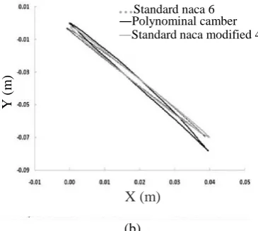
The radial distribution of the stagger angle is shown in Fig. 7. The distribution of the stagger angle in both cases with standard airfoils (cases II, III) is almost coincident. The stagger angle of blade with polynomial camber in the rotor is approximately 10 degrees higher than standard airfoils. This difference in the stator is higher so that the stagger angle in this case (case I) is about half of the other two cases. It can be concluded that although employing the standard airfoils in the stator (cases II, III) produces lower losses in comparison to case I, this leads to greater twist of blades that is undesirable. The final result of the Aerodynamic Design process of an axial compressor is the 3D geometric shape of the blades. The rotor blade profile in the hub and at the tip of all considered cases is illustrated in Fig. 8. As can be observed, the obtained blade shape for three cases is different. The sharpness of the leading edge is one of the characteristics of naca profile series 6 which is seen for cases I, II. The large thickness of naca airfoil series 4 at the tip of the blade can lead to bow shock detachment and consequently produce more losses. In Fig. 8(b) it can be seen that the polynomial camber line (case I) has taken an s-shape curve to match with streamline. But this does not occur in standard naca airfoils (cases II, III).
(a)
(b)
Fig. 5. Distribution of the pressure ratio on the first stage (a) rotor (b) stator.
(a)
(b)
Fig. 6. Distribution of the diffusion factor on the first stage (a) rotor (b) stator.
P
er
ce
n
tag
e
o
f
sp
an
f
ro
m
h
u
b
(%)
Pressure ratio
---Standard naca 6
―Polynominal camber
…Standard naca modified 4
P
er
ce
n
tag
e
o
f
sp
an
fr
o
m
h
u
b
(
%)
Pressure ratio
---Standard naca 6 ―Polynominal camber …Standard naca modified 4
DF
P
er
ce
n
tag
e
o
f
sp
an
fr
o
m
h
u
b
(
%)
---Standard naca 6
―Polynominal camber
…Standard naca modified 4
P
er
ce
n
tag
e
o
f
sp
an
fr
o
m
h
u
b
(
%)
DF
---Standard naca 6
―Polynominal camber
(a)
(b)
Fig. 7. Distribution of the stagger angle on the first stage (a) rotor (b) stator.
(a)
(b)
Fig. 8. blade profile shape of the first stage (a) hub (b) tip.
6. Conclusions
In this paper, the effects of the blade shapes on the aerodynamic design characteristics were investigated based on Streamline Curvature Method (SCM).
Initially, the SCM was used for designing a two stage axial compressor. Comparing the presented results with experimental ones showed good agreement. For surveying the effects of the blade profile, three different cases for the geometric shape of the blade including polynomial camber line with series 6 thickness (case I), standard naca airfoil series 6 (case II) and standard modified airfoil series 4 (case III) were considered. Span wise distribution of results such as meridional velocity, diffusion factor, stagger angle and blade shape in all cases were compared. The main conclusions drawn from this study can be stated as follows: Variation of meridional velocity in the rotor
is greater than the stator in all cases. Although, the radial variation of meridional velocity in the rotor is more uniform in the blade with polynomial camber (case I), but it changes significantly by using standard airfoils in cases II and III. Applying blades with standard airfoil (cases II, III) leads to higher meridional velocity at the tip and lower in the hub of the compressor.
The use of standard airfoils in stators leads to improved flow conditions including loss coefficient and pressure ratio, but it leads to
P
er
ce
n
tag
e
o
f
sp
an
fr
o
m
h
u
b
(
%)
ζ (degree)
---Standard naca 6
―Polynominal camber
…Standard naca modified 4
P
er
ce
n
tag
e
o
f
sp
an
fr
o
m
h
u
b
(
%)
ζ (degree)
---
Standard naca 6 ―Polynominal camber …Standard naca modified 4Y
(m
)
X (m)
…Standard naca 6
―Polynominal camber
―Standard naca modified 4
Y
(m
)
X (m)
…Standard naca 6
―Polynominal camber
an increase in stagger angle and blade twist. Between the standard airfoils, the naca series 6 revealed the better behavior in comparison to the modified airfoil series 4.
Using blades with polynomial camber line in the rotor caused better aerodynamic results in loss values, pressure ratio and diffusion factor; whilst, the use of such a camber line in the stator leads to formation of less favorable aerodynamic conditions.
Acknowledgement
The authors declare that there is no conflict of interests regarding the publication of this paper. No funding in this article.
References
[1] R. N. Sharma, “Economics of mine ventilation,” In Proceedings of International Conference on Mineral Industry: Issues on Economics, Environment and Technology (pp. 75– 87). India: The Mining, Geological and Metallurgical Institute of India, (2002). [2] B. Eck, Fans; “design and operation of
centrifugal, axial flow,” and cross-flow fans, Oxford: Pergamon Press, (1973). [3] P. K. Sen, “Reducing power
consumption for axial flow mine ventilation fans,” Journal of Mines, Metals and Fuels, Vol.45, No. (9–10), pp. 301–303, (1997).
[4] W. A. Hustrulid & R. L. Bullock, “Underground mining methods: engineering fundamentals and international case studies,” Englewood, CO: Society for Mining, Metallurgy and Exploration, (2001).
[5] J. Herricl, E. ameesm, and E. Johnr, “Systematic Two-Dimensional Cascade Tests of NACA 65-Series Compressor Blades at Low Speeds,” NACA-TR-1368, (1951).
[6] I. Felixr, “Summary of 65-Series Compressor-Blade Low-Speed Cascade Data by Use of the Carpet-Plotting Technique, NACA-TN-3913, (1954).
[7] Mellorg, “Aerodynamic Performance of Axial Compressor Cascades with Application to Machine Design,” MIT Gas Turbine Lab, Report, No. 3S, (1957).
[8] B. Lakshminarayana, “Fluid Dynamics and Heat Transfer of Turbomachinery,”
John Wiley & Sons, New York, (1996). [9] V. Pachidis, “Prediction of engine
Performance under Compressor inlet Flow Distortion Using Streamline Curvature,” J. Eng. Power, Vol. 89, No. 4, pp. 478-490, (2006).
[10] Hearsey، R. M, “Practical Compressor Aerodynamic Design, Advanced Topics in Turbomachinery Technolog,” Principal Lecture Series No. 2, Concepts ETI, 1986.
[11] I. Templalexis, P. Pilidis, V. Pachidis, and P. Kotsiopoulos, “ Development of a Two-Dimensional Streamline Curvature Code,” J. Turbomach, Vol. 133, No. 1, 0110031-7, (2011).
[12] J. F. Hu, H. Ou-Yang, X. Ch. ZHu, X. Q. Qiang, and Z. Du, “An improved streamline curvature approach for transonic axial compressor performance prediction,” J. Aerospace Engineering
Vol. 225, No. 5, 575-584, (2011). [13] W. Gong, R. Kang, W. Bin Zhang, “A
new finite difference method to solve the velocity gradient equation in streamline curvature method,” Advances in Mechanical Engineering, Vol. 8, No. 9, pp. 1–13, (2016).
[14] C. C. Koch, L. H. Smith, “Loss Sources and Magnitudes in Axial Flow Compressors,” Transactions of the ASME, Journal of Engineering for Power, Vol. 98, No. 3, pp. 411-424, (1976).
[15] W. C. Swan, “A Practical Method of Predicting Transonic-Compressor Performance,” Journal of Engineering for Power, Vol.83, No. 3, pp. 322–330, (1958).
[17] JA Storer and NA cumpsty, “An approximation analysis and prediction method for tip clearance loss in axial compressors,” J. Turbomach, Vol. 116, No. 4, pp. 648-656, (1994).
[18] S. Lieblein, “Incidence and Deviation-Angle Correlations for Compressor Cascades,” J. Basic Eng Vol. 82, No. 3, pp. 575-584, (1960).
[19] NA. Cumpsty, “Compressor aerodynamics,” John Wiley & Sons. New York, (1989).
[20] D. C. Urasek, T. G. William, W. S.
Cunnan, “Performance of a Two Stage Fan Having Low Aspect Ratio First Stage Rotor Blading,” NASA Technical Paper 1493, (1979).
[21] G. R. Frost, R. M. Hearsey, A. J. Wennerstrom, “a computer program for the specification of axial compressor airfoils,” project 7065, Aerospace Research Laboratories, (1972).
[22] I. H. Abbott, A.E. Von Doenhoff, “Theory of Wing Sections: Including a Summary of Airfoil Data,” (1959).
How to cite this paper:
Sarallah Abbasi and Ali Joodaki, “Effect of blade profile on the performance characteristics of axial compressor in design condition”, Journal of Computational and Applied Research in
Mechanical Engineering, Vol. 9, No. 2, pp. 287-296, (2019).