Technical Specification Group Services and System
Aspects, IP Multimedia Subsystem (IMS)
Ashwini PatilDepartment of Information Technology, Bharati Vidyapeeth Deemed University College
Of Engineering, Pune-46
H. K. Sawant
Department of Information Technology, Bharati Vidyapeeth Deemed University
College Of Engineering, Pune-46
Abstract—The paper is aimed at studying and analyzing the network performance parameters of SIP protocol. SIP is content based protocol, in which various message are required to be transacted so that a session could be created, terminated or modified. Therefore, the objective is to analyze various SIP activities and the delay incurred in session start-up under various network conditions. The overall project is split into key areas like Networking, Traffic modeling, Simulation and Reporting. The objectives behind the work are as follows: Getting acquainted with the concept of IMS, SIP and their functionalities, To define a Hybrid Network Topology consisting of the IMS entities and the fixed and mobile SIP User Agents, To set the proper configuration of the nodes such that they are able to communicate with each other properly, To identify the parameters based on which the performance evaluation will be done, To find the options of specifying different types of traffic flow in the network, To vary the parameters for different scenarios and simulate them, To study the variation in the results and analyze the performance of SIP protocol in the network.
Key Words— SIP protocol, SIP activities and the delay incurred in session, IMS platform, DIAMETER- improvised version of RADIUS protocol.
I. I
NTRODUCTIONIn the past few years, the evolution of cellular networks has reflected immense success and growth which was experienced by Internet in the last decade. This leads to networks where Internet Protocol connectivity is provided to mobile nodes. The result is third generation (3G) networks where IP services such as voice over IP (VoIP) and instant messaging (IM) are provided to mobile nodes (MN) in addition to connectivity. With import of Wi-Fi, Wi-MAX, digital video broadcasting, satellite, internet, etc. the current architecture of telecommunication network has been facing a challenge of interoperability.
Hence, the solution was to devise an interoperable platform which can provide the services irrespective of the access technology. The basic approaches to convergence are:
UMA: Unlicensed Mobile Access (UMA) is a new
technology that provides access to GSM services over Wireless LAN or Bluetooth. It also challenges the assumption of closed platform, since it is relatively easy to implement a UMA phone purely in software running on standard PC hardware and operating systems. In the UMA solution, exiting cellular network remains unmodified, and a new network element, the UMA Network Controller (UNC), is introduced. UNC acts as a gateway between the mobile operator core network and Internet or a broadband IP access network such as ADSL or cable. The phone connects to the IP network using a standard WLAN or
Bluetooth access point. Since GSM/GPRS core security mechanisms; new mechanisms are defined only for protecting the communication between the phone and UNC.
SIP: The Session Initiation Protocol (SIP) is a signaling
protocol used for establishing sessions in an IP network. A session could be a simple two-way telephone call or it could be a collaborative multi-media conference session. The ability to establish these sessions means that a host of innovative services become possible, such as voice-enriched e-commerce, web page click-to-dial, Instant Messaging with buddy lists, and IP Centrex services. SIP is a request-response protocol that closely resembles two other internet protocols, HTTP and SMTP; consequently, SIP sits comfortably alongside Internet application. Using SIP, telephony becomes another web application and integrates easily into other Internet services. SIP is a simple toolkit that service providers can use to build converged voice and multimedia services. SIP is an “application-layer control (signaling) protocol for creating, modifying, and terminating sessions with one or more participants. These sessions include Internet telephone calls, multimedia distribution, and multimedia conferences.”
IMS: IP Multimedia Subsystem (IMS) is referred as the
heart of NGN. The 3GPP has published a number of specifications that define the IMS as the part of the 3G wireless environment which will“enable the convergence of, and access to, voice, video, messaging, data and web-based technologies for the wireless user.” The 3GPP defined the IMS specifications in support of the Universal Mobile Telecommunication System (UMTS). The UMTS is the 3G evolution of the GSM.
IMS is the envisioned solution that will provide new multimedia rich communication services by mixing telecom and data on an access independent IP based architecture, defined in 3rd Generation Partnership Project (3GPP), 3rd Generation Partnership Project 2 (3GPP2) and Internet Engineering Task Force (IETF) standards.
access and Internet technologies to provide appealing services.
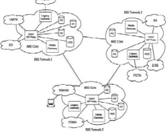
Figure 1: IMS Overview NGN Convergence
II. L
AYEREDA
RCHITECTURE OFIMS
The definition of IMS by 3GPP is an all packet core network that is able to accept all types of access networks i.e. WiMAX, CDMA, GSM in order to deliver a wide range a multimedia services which can be offered to the user by any device connected to the network. The use of SIP in IMS enable the support of IP-to-IP sessions over any wire-line connection system like DSL as well as wireless networks like Wi-Fi, GSM and CDMA. The IMS allows the inter-working between the traditional TDM networks and the IP networks.
A. Access Layer
The IMS architecture is independent of any access bearer. In the mobile networks the access layer could be any or a combination of the following: General Packet Radio Service (GPRS), Enhance Data Rate for GSM Evolution (EDGE), Code Division Multiple Access (CDMA), Wireless Interoperability for Microwave Access (WiMAX), Universal Mobile Telecommunication System (UMTS) and Wireless Local Area Networks (W-LAN or Wi-Fi). The fixed line networks makes use of Asymmetric Digital Subscriber Lines (ADSL) and cable network accesses.
B. Transport Layer
This is an all IP network which consist of IP Routers. These routers are Label Edge Routers and Core Switching Networks. The IP/MPLS (Multi-protocol cable Switching) is the transport layer technology for IMS platform. MPLS defines a mechanism for the forwarding of packets in a router network. Due to its flexibility, the MPLS has become the default IP transport network for the Next Generation Networks making use of the IMS core in order to reliability and Quality of Service.
C. Session Control Layer:
This layer consists of network control servers which are used for the management of calls, establishment and modifications of sessions in the IMS platform. Two main elements in this layer are the Call Session Control Function (CSCF) and the Home Subscriber Server (HSS). These two elements form the core of the ISM architecture and are sometimes referred to as SIP Servers. The CSCF provide end-point registration and routing of SIP signaling
messages and provide interworking with the transport layer for guaranteed QoS of all services. The HSS is the database that is used to store the subscriber service profiles and service triggers. The other information stored by the HSS includes the dynamic data of the subscribes like location information.
D. Application layer
This layer makes use of application and content servers to provide value-added services. The Application Server (AS), the Multimedia Resource Function Controller (MRFC) and Multimedia Function Resource processor (MFRP) form the core of this layer. The AS is responsible for the execution of service-specific logic i.e. user interaction with subscribers and call flows. The MRFP is also known as IP media server is used to provide media processing for the application layer. The media server is used to enable to delivery of some non-telephony services like Push-to-Talk (PTT), speech enabled services, video services and other services like conferencing, prepaid and personalized call-back tones.
The control and application layers are access and transport independent and this is very useful in order to ensure that the user is able access the ISM services required from any access network and from any connection device.
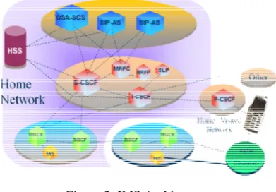
Figure 2: Layered Architecture of IMS
III. IMS A
RCHITECTURED
ESIGNIn the General architecture of IMS, 3GPP standardize functions but not nodes. So we can say that the IMS architecture is a collection of functions linked by standardized interfaces. If any implementer want they can merge two functions into single node as well as they can divide single function into two or more nodes. Figure 3 shows an overview of the IMS architecture as standardized by 3GPP.[1,2] Here we include only most important nodes. The common nodes included in the IMS are as follows:
CSCF is a SIP (Session Initiation Protocol) server which processes SIP signaling in the IMS. CSCFs are dynamically associated, service-independent and standardized access points. It distributes incoming calls to the application services and handles initial subscriber authentication. There are three types of CSCFs depending on the functionality they provide.
P-CSCF (Proxy-CSCF): The P-CSCF is the first point of contact between the IMS terminal and the IMS network. All the requests initiated by the IMS terminal or destined to the IMS terminal traverse the P-CSCF. This node provides several functions related to security. The P-CSCF also generates charging information toward a charging collection node. An IMS usually includes a number of CSCFs for the sake of scalability and redundancy. Each P-CSCF serves a number of IMS terminals, depending on the capacity of the node.
I-CSCF (Interrogating-CSCF): The I-CSCF provides the functionality of a SIP proxy server. It also has an interface to the SLF (Subscriber Location Function) and HSS (Home Subscriber Server). This interface is based on the Diameter protocol (RFC 3588). I-CSCF retrieves user location information and routes the SIP request to the appropriate destination, typically an S-CSCF.
S-CSCF (Serving-CSCF): The S-CSCF is a SIP server that performs session control. It maintains a binding between the user location and the user’s SIP address of record (also known as Public User Identity). Like the I-CSCF, the S-CSCF also implements a Diameter interface to the HSS.
B. SIP AS (Application Server)
The AS is a SIP entity that hosts and executes IP Multimedia Services based on SIP.
C. MGCF (Media Gateway Control Function)
MGCF implements a state machine that does protocol conversion and maps SIP to either ISUP (ISDN User part) over IP or BICC (Bearer Independent Call Control) over IP. The protocol used between the MGCF and the MGW is H.248 (ITU-T Recommendation H.248).
D. MGW (Media Gateway)
The MGW interfaces the media plane of the PSTN (Public Switched Telephone Network) or CS (Circuit Switched) network. On one side the MGW is able to send and receive IMS media over the Real-Time Protocol (RTP). On the other side the MGW uses one or more PCM (Pulse Code Modulation) time slots to connect to the CS network. Additionally, the MGW performs trans-coding when the IMS terminal does not support the codec used by the CS side.
E. HSS (Home Subscriber Server)
It contains all the user related subscription data required to handle multimedia sessions. These data include, among other items, location information, security information (including both authentication and authorization information), user profile information and the S-CSCF allocated to the user. The SLF (Subscription Location Function) is a simple database that maps users’ addresses to HSSs. Both the HSS and the SLF implement the Diameter protocol.
Figure 3: IMS Architecture
IV. S
IGNALINGA main question in integration of circuit switched network and packet switched network is of signaling. Both the networks use different sort of signaling, which requires to be mapped into the form, which used by other network when necessary to navigate the links of that network.[4,6] Following table shows the signals used by both type of networks and their equivalent at either sides:
Table 1: PSTN and SIP equivalent signals
IP PSTN
INVITE TRYING
IAM (Initial Address Message)
RINGING ACM (Answer Complete Message)
OK ANM (Answer Message)
BYE REL (Release)
OK RLC (Release Complete)
The protocol stack shows layer by layer usage of different protocols. At Physical Layer SONET, ATM, V.34 etc are used. Likewise at Network Layer IPv4 & IPv6(not currently) are being used. Transport Layer uses TCP and UDP. Finally at Application Layer for signaling SIP, SDP, MGCP, H.323, RTSP are used. Finally for Quality of Service RSVP and RTCP are used and for video transmission RTP is used.
Figure 3: Protocol Stack
In practice, there are two main protocols used for initiating multimedia sessions viz. H.323 and SIP.
The first one is H.323, specified by ITU-T for the implementation of multimedia services. It is not a single standard but is an umbrella of standards. This protocol was originally created to provide a mechanism for transporting multimedia applications over LANs but it has rapidly evolved to address the growing needs of IP networks. One strength of H.323 was the relatively early availability of a set of standards, not only defining the basic call model, but in addition the supplementary services, needed to address business communication expectations. H.323 was the first VoIP standard to adopt the IETF standard RTP to transport audio and video over IP networks.
B. SIP
Session Initiation Protocol (SIP) [14, 16] is an application-layer signaling protocol that can establish, modify, and terminate multimedia sessions (conferences) such as Internet telephony calls. SIP can also invite participants to already existing sessions, such as multi-cast conferences. Media can be added to (and removed from) an existing session. SIP transparently supports name mapping and redirection services, which supports personal mobility - users can maintain a single externally visible identifier regardless of their network location. SIP supports five facets of establishing and terminating multimedia communications:
• User location: Determination of the end system
to be used for communication.
• User availability: determination of the willingness of the called party to engage in communications.
• User capabilities: Determination of the media
and media parameters to be used.
• Session setup: “Ringing”, establishment of session parameters at both called and calling party.
• Session management: Including transfer and
termination of sessions, modifying session parameters, and invoking services.
V. S
YSTEMD
ESCRIPTIONSeveral works analyzed the subject of SIP signaling from different angles. All these works did not associate any constraints to the access network and assumed an infinite bandwidth over the link between the User Agents, IMS entities and intermediate routers. This assumption is not true and the impact of SIP signaling on the network and its consequences on the SIP nodes must be evaluated. Apart from this, most of the studies were carried out with topology containing either fixed nodes or mobile nodes only; therefore the performance of a hybrid topology can be studied too.
So keeping in mind the drawback of the previous works, we propose a topology consisting of both mobile and fixed nodes with proper specification of suitable links between them. Statistic to be obtained
1. Tunneled Traffic Sent/Received: Amount of traffic tunneled by Agents and de-tunneled by agents and hosts. It is given in packets/sec.
2. Jitter: If two consecutive packets leave the source node with time stamps t1 & t2 and are played back at the destination node at time t3 & t4, then:
Jitter = (t4 - t3) - (t2 - t1)
Negative jitter indicates that the time difference between the packets at the destination node was less than that at the source node. It is given in sec.
3. Packet End to End Delay: The total voice packet delay, called "mouth-to-ear" delay = network delay + encoding delay + decoding delay + compression delay + decompression delay. Specified in seconds.
4. Wireless LAN Delay: Represents the end to end delay of all the packets received by the wireless LAN MACs of all WLAN nodes in the network and forwarded to the higher layer. Specified in seconds.
5. Retransmission Attempts: Total number of retransmission attempts by all WLAN MACs in the network until either packet is successfully transmitted or it is discarded as a result of reaching short or long retry limit. Specified in packets.
6. Registration Traffic Sent/Received: Amount of Mobile IP registration packets sent/received. Mobile IP nodes and router register their addresses with agent nodes (home/foreign) to receive mobile ip service.
7. Throughput: This statistic represents the average number of packets successfully received or transmitted by the receiver or transmitter channel per second.
8. Utilization: This statistic represents the percentage of occupancy of an available channel bandwidth with respect to time period, where a value of 100.0 would indicate full usage.
9. SIP Active Calls: Number of active calls at any given time.
10. Call Setup Time: Time to setup a call in seconds. 11. Calls Connected: It includes calls initiated by this node and also the incoming call requests.
12. Calls Initiated: Number of calls initiated at a particular SIP UAC node.
13. Call Duration: Duration of each call defined as the time at which the node got call connect confirmation to the time at which it got call disconnect confirmation.
VI. C
ONCLUSIONIn this work we have to analyze the impact of different types of traffic load with varying pattern of the SIP signalling carried over the network. We need to configure a hybrid network topology consisting of IMS entities I-CSCF, P-I-CSCF, S-I-CSCF, intermediate routers and SIP enabled fixed and mobile nodes. Then we have to create different scenarios and varied their respective parameters. Other signalling protocol like H.323, etc, do not support mobility but SIP handles this problem because of the Mobile IP support. The IMS is based on Session Initiation Protocol (SIP) which is a text based protocol. The IMS will generally create additional signaling traffic in the IP based networks, so there is a need to take necessary precautions to minimize the signaling overload.
R
EFERENCES[1] 3GPP, TSG SSA, IP Multimedia Subsystem (IMS)–Stage 2 (Release 7), TS23.228 v.7.3.0,2006-03.
[2] 3GPP, Technical Specification Group Services and System Aspects, IP Multimedia Subsystem (IMS) - Stage 2 (Release, TS 23.228 v5.6.0, 2002-09.
[3] 3GPP, Technical Specification Group Services and System Aspects: QoS Concept and Architecture (Release 5), TS 23.207 v5.6.0, 2002-09.
[4] 3GPP, Technical Specification Group Core Network; Signalling flows for the IP multimedia call control based on SIP and SDP; Stage 3 (Release 5), TS 24.228 v5.2.0, 2002-09.
[5] C. Perkins, "IP mobility support for IPv4," RFC 3344, Internet Engineering Task Force,2002.
[6] V. Planat, N. Kara;“SIP Signaling retransmission analysis over 3Gnetwork”,Proceedings of MoMM 2006
[7] Jie Xiao, Changcheng Huang and James Yan;“AFlow- based Traffic Model for SIP Messages inIMS”, 978-1-4244-4148-8/09 IEEE "GLOBECOM" 2009 proceedings.
[8] Arslan Munir, Gordon Ross, “SIP-Based IMS Signaling Analysis for WiMax-3G Interworking Architectures”, 1536-1233/10 IEEE Transactions on mobile computing, Vol. 9, No. 5, May 2010.
[9] 3GPP. TS 24 229“IPMultimedia Call Control Protocol based on Session Initiation Protocol (SIP) and Session Description Protocol (SDP)”V5.16.0, March 2006.
[10] Session Initiation Protocol (SIP), RFC 3261, H. Schulzrinne, J. Rosenberg. June 2002
[11] GPP. TS 24 228 Signalling flows for the IP multimedia call control based on Session Initiation Protocol (SIP) and Session Description Protocol (SDP) V5.14, December 2005.
A
UTHOR’
SP
ROFILE Ashwini Patilpursuing M.Tech from Information Technology Department at Bharati Vidyapeeth Deemed University College of Engineering, Dhankawadi, Pune India. Her areas of interest are Software Engineering and networks.
H. K. Sawant