INTRODUCTION
Cylindrical gears can undergo height cor-rection of the profile which does not cause any change in the distance between their axes or they can be subjected to angular correction of the file, which does. Besides, the coefficients of pro-file correction can have different values. Part 1 of this study reported the results of a study in-vestigating a cylindrical helical gear with height correction of the profile. The investigation was conducted using a new method for determining the wear and durability of toothed gears [1]. This paper reports the results obtained for the cylin-drical gear with angular correction of the profile depending on the type of engagement [3].
SOLUTION TO THE PROBLEM
In the helical cylindrical gears with angular correction of the profile, the correction coeffi-cients are x1 ≠ x2 and the total coefficient of pro-file correction is xΣ = x1 + x2. The real distance
awk between the axes will be higher than the nominal distance aw:
1 2
wk w w w
a
=
r
+
r a
〉
(1)The rolling pressure angle αw will depend on the real distance between the axes of the meshing gears and will be higher than the apparent pres-sure angle αt. When the real distance between the axes is known
arccos w cos
w t
wk a a
α = α (2)
The radii of the pinion and gear:
2 2
cos
cos
α
=
α
t ww
r
r
(3)The radius of the addendum:
1 1
(1
1) ,
2 2(1
2) ,
a a
r
= + + −
r
x K m r
= + +
r
x
−
K m
1 1
(1
1) ,
2 2(1
2) ,
a a
r
= + + −
r
x K m r
= + +
r
x
−
K m
(4)where is the coefficient of addendum reduction. The equations wherein the above pa-rameters of profile correction must be taken into consideration [2]:
1 1
9550 g / w cos w
N = PK r n α (5)
Computer Simulation of the Impact of Optimization of Width
in the Helical Cylindrical Gear on Bearing and Durability.
Part 2. Angular Correction of the Gear Profile
Myron Czerniec
11 Lublin University of Technology, ul. Nadbystrzycka 36, 20-618 Lublin, Poland, e-mail: [email protected]
ABSTRACT
On the basis of the elaborated calculation method, the optimal width in involute helical gears was determined ensuring a constant length of the line of contact between the meshing gears that is based on the novel method for determining the wear and durability of the gears which was employed to measure the maximum contact pressures, linear wear of teeth and durability of the gear with angular correction of the profile. It was possible to determine the variations in the parameters for the optimized gear describing the meshing gears at different values of the profile correction coefficients.
Keywords: block calculation method, cylindrical helical gear, angular correction of engagement, optimal gear width, maximum contact pressures, tooth wear, gear durability
Volume 13, Issue 2, June 2019, pages 1–6
https://doi.org/10.12913/22998624/99038
Research Journal
Accepted: 2019.04.09Advances in Science and Technology Research Journal Vol. 13(2), 2019
(
)
(
)
2 210 1 cos 20 / 2 cos
t w w w
w u
tgα = +u tgα − r r − α
α
(
)
(
)
2 210 1 cos 20 / 2 cos
t w w w
w u
tgα = +u tgα − r r − α
α
(6)
(
)
2 21 1 / 1 cos
t s arctg r rs w w
α = − α
(
)
2 22 2 2 / 2 cos
t j rw r rj w w
ρ = − α (7)
(
)
2 2
2j w 1j
2
w j1cos
w t j1r
=
a
+
r
−
a r
α − α
1j w1cos w/ cos t j1
r =r α α (8)
(
1)
(
)
2 22 1 cos1 1 / 1 cos
t s w s w w
w
tg u tg r r
u
−
α = + α − − α
α
(
1)
(
)
2 22 1 cos1 1 / 1 cos
t s w s w w
w
tg u tg r r
u − α = + α − − α α (9)
(
)
2 arccos 2/ 2 cos
t j r rw j w
α = α (10)
2 2
1 1s b1 w1
sin
we
=
r
−
r
−
r
α
2 2
2 20 b2 w2
sin
we
=
r
−
r
−
r
α
(11)NUMERICAL SOLUTION
The input data included: z1 = 20; z2 80; m = 3 mm; u = 4; n1 = 700 revolutions per min-ute; P = 5 kW; f = 0.05; β = 10o; K
g = 1.6. The fol-lowing materials were used: the pinion was made of 38HМJА steel after nitriding with 58 HRC; Rm = 1040 MPa, C1= 3.5·106m1 = 2; the gear was made of 40H steel after bulk heat treatment with 53 HRC, Rm = 981 MPa, C2= 0.17·106, m2 = 2,5; E = 2.1·105ּ МPа. Lubrication involved the use
of an oil characterized by the kinematic viscos-ity v+50° ≈ 15 сSt; hk* = 0.5 mm; Δφ = 40. The
profile correction coefficients and the geo-metrical parameters of the gear were as fol-lows: x1 = 0 … 0.5, x2= 0 … 0.584; xΣ 0.584;
aw = 152.314 mm; awk = 154 mm; αt = 20.283o; αw = 21.918o. The width of the gear wheels: bw = 54.275 mm while lmin= const and εβ = 1; bw = 30 mm while lmin ≠ const and εβ< 1. The
gear with bw= 54.275 mm is described by triple-double-triple engagement, while the gear with bw = 30 mm by double-single-double engage-ment. The calculations were performed using a block calculation method from the quantity of the interaction block B = 2100000 rpm.
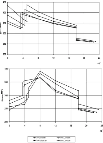
The numerical results are given in the figures below. Figure 1a shows the initial maximum con-tact pressures pjmax which occur during
triple-dou-ble-triple engagement while Figure 1b illustrates the variations in
max
jh
p
due to the wear of gear teeth amounting to 0.5 mm.
The highest contact pressures pjmax can be observed at the start of double engagement. Lat-er on, when the meshing gears are in triple en-gagement, the pressures pjmax decrease by up to
1.7 times. In other cases, the decrease in the pres-sures is smaller and depends on the values of the profile correction coefficients.
Figures 2 and 3 illustrate the linear wear of the gear teeth h2j and the pinion h1j.
The maximum allowable wear is first reached by the gear teeth at different characteristic points of pressure depending on the values of the pro-file correction coefficients – at the start of triple engagement and almost at the start of double engagement (Fig. a) or at the end of double en-gagement (Fig. b). Similar observations can be made with the maximum allowable wear of the pinion teeth.
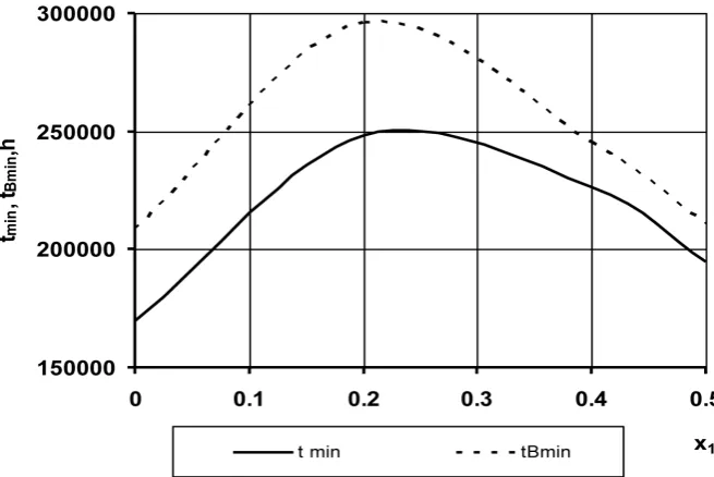
The relationship between the minimum du-rability of the gear and profile correction is shown in Figure 4.
The highest durability can be observed for the gear with profile correction when x1 ≈ 0.2, x2 ≈ 0.384; this value is higher by 1.40 than that of the gear without profile correction.
In order to compare the effect of the gear width on the type of engagement, the results of the contact, wear and durability of two gears are as follows: the gear described by the width r and double-single-double engagement and the gear described by the width bw = 54.275 mm and triple-double-triple engagement. Figure 5 presents the results of the maximum contact pressures pjmax for the two tested gear widths.
Therefore, increasing the gear width by 1.81 times leads to an almost proportionate de-crease (by 1.86 … 1.8 times) in the initial con-tact pressures at the start of engagement and by 1.89 ... 1.92 times at the points of change of the type of engagement. It must be emphasized that the double engagement zone of the gear with the width bw = 54.275 mm is 3–4 times higher than in the case of narrower gears, which is vital from a practical point of view.
Fig. 1. Variations in the pressures pj max during the meshing of the teeth due to their wear
Advances in Science and Technology Research Journal Vol. 13(2), 2019
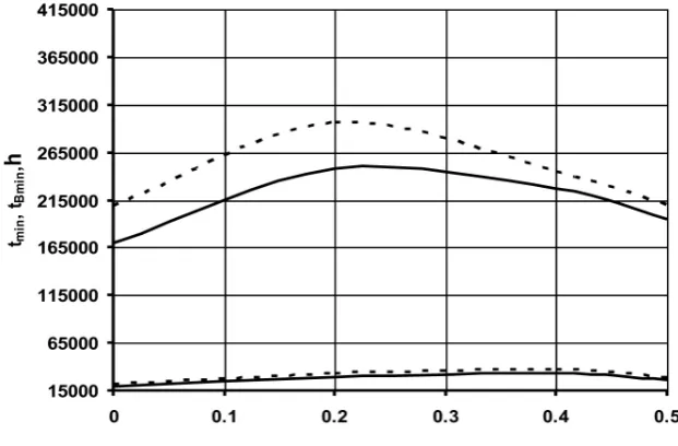
For the gear with the profile correction coeffi-cients x1 ≈ 0, x2 ≈ 0.584, the durability increas-es by 9.2 timincreas-es, and when the optimum profile correction coefficients are applied x1 ≈ 0.2, x2 ≈ 0.384 – by 8.8 times.
A similar effect of gear width can also be observed in the case of the gear with profile correction, as described in Part 1 of the paper. Therefore, it can be concluded that the two tested types of profile correction exert a similar impact on the contact and tribotechnical param-eters of the gear.
CONCLUSIONS
1. A numerical problem concerning the setting of maximum contact pressures, linear wear and durability of cylindrical gears was solved using an original method for determining the wear and durability of gears which takes into account the profile correction and type of engagement. 2. Two types of gear were examined: a gear with
optimized width of the gear wheels ensuring a constant force between the meshing teeth and a gear with a smaller width of the gear wheels. Fig. 4. Minimum durability of the gear versus profile correction: solid line –
tmin when pj max = const, dotted line – tB min when pjh max = var
Fig. 5. Maximum contact pressures (a) and their variations (b) due to wear
of the teeth: bw = 30 mm (top), bw = 54.275 mm (bottom)
Fig. 6. Impact of profile correction on minimum durability of the gear
Advances in Science and Technology Research Journal Vol. 13(2), 2019
3. It was found that the increase in the gear width ranging from 30 to 54.275 mm results in an al-most proportionate decrease in the maximum contact pressures.
4. The increase in the gear width by 1.81 times leads to a considerable increase in the minimum dura-bility of the gear – by 9.2–8.8 times, depending on the value of the profile correction coefficient. 5. Regardless of the type of applied profile
cor-rection (angular or height corcor-rection of the gear profile), the width of the gear wheels has the greatest impact on the contact strength and wear of the gear teeth.
6. The application of suitable values of the cor-rection coefficients of the pinion and the gear lead to a uniform wear of the gear teeth for both engagement zones.
REFERENCES
1. Chernets M.V., Yarema R.Ya., Chernets Yu.M., A method for the evaluation of the influence of correction and wear of the teeth of a cylindri
-cal gear on its durability and strength. Part 1. Service live and wear. Materials Science, 2012, 3, 289–300.
2. Chernets M., Kiełbiński J., Chernets Yu., A study on the impact of teeth meshing conditions and profile correction on the carrying capacity, wear and life of a cylindrical gear. Tribologia, 2016, 2, 25–43.