2D Computational Fluid Dynamic Modeling of Human
Ventricle System Based on Fluid-Solid Interaction and
Pulsatile Flow
Nafiseh Masoumi1*, F. Framanzad2*, Behnam Zamanian3*, A.S. Seddighi4, M.H. Moosavi5, S. Najarian6, Dariush Bastani7
1. Chemical & Petroleum Engineering Department, Sharif University of Technology, Tehran, Iran.
2. Biomechanics Group Faculty, Mechanical Engineering Department, Iranian University of Science and Technology, Tehran, Iran. 3. Department of Chemical Engineering, North Eastern University, Boston, MA,USA.
4. Neurosurgery Department, Shohada-e-Tajrish Hospital, ShahidBeheshti University of Medical Sciences, Tehran, Iran. 5. Biomedical Engineering, Amirkabir University of Technology, Tehran, Iran.
6. Faculty of Biomedical Engineering, Amirkabir University of Technology, Tehran, Iran.
7. Faculty of Chemical & Petroleum Engineering Department, Sharif University of Technology, Tehran, Iran.
* Corresponding Author: Dariush Bastani, PhD
Faculty of Chemical & Petroleum Engineering Department, Sharif University of Technology, Tehran, Iran
1. Introduction
he area around the spinal cord and the brain
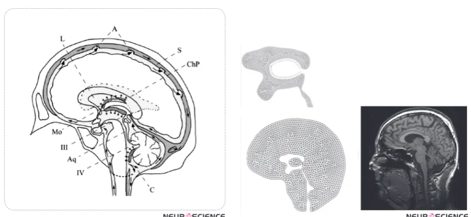
contains the cerebrospinal fluid (CSF) as depicted in figure 1. From the hydrodynam -ic point of view, the circulatory dynam-ics
of cerebrospinal fluid and that of cerebral
blood within brain tissues give rise to intracranial pres-sure (ICP) which can in turn be affected by infectious
diseases. Since the flow pattern of CSF within the Hu -man Ventricular System (HVS) is complicated due to its complex geometry, investigating the CSF and
ce-T
Many diseases are related to cerebrospinal fluid (CSF) hydrodynamics. Therefore, understanding the hydrodynamics of CSF flow and intracranial pressure is helpful for obtaining
deeper knowledge of pathological processes and providing better treatments. Furthermore, engineering a reliable computational method is promising approach for fabricating in vitro models which is essential for inventing generic medicines.
A Fluid-Solid Interaction (FSI)model was constructed to simulate CSF flow. An important problem in modeling the CSF flow is the diastolic back flow. In this article, using both rigid and flexible conditions for ventricular system allowed us to evaluate the effect of surrounding
brain tissue. Our model assumed an elastic wall for the ventricles and a pulsatile CSF input as its boundary conditions. A comparison of the results and the experimental data was done. The
flexible model gave better results because it could reproduce the diastolic back flow mentioned
in clinical research studies. The previous rigid models have ignored the brain parenchyma
interaction with CSF and so had not reported the back flow during the diastolic time. In this computational fluid dynamic (CFD) analysis, the CSF pressure and flow velocity in different
areas were concordant with the experimental data.
A B S T R A C T
Article info:
Received: 2 September 2012
First Revision: 16 October 2012
Accepted: 25 October 2012
Key Words:
Cerebrospinal Fluid, FSI modeling, Pulsatile, Hydrodynamics,
Computational Fluid Dynamics (CFD)
rebral blood hemodynamic, by means of HVS model-ing or simulation, allows the physician to gather ac-curate information about CSF dynamics and provides the opportunity to diagnose effective mechanisms of brain diseases and apply appropriate medical or surgi-cal interventions. Furthermore, it will help diagnosis of diseases such as hydrocephalus in more persist and
efficient manner. Additionally, recent researches show that the fluid dynamic has significant effect on stem cell
early stages. Having models with consistent similarities with in vivo conditions enhances fabrication of in vitro models which is not only essential for lab studies(Whyte et al., 2012), but also plays an important role in custom designed treatments(Whyte et al., 2012) .
Various mathematical models known as lumped pa-rameter models are in place to help establish the com-plex situations leading to ICP alterations in people suf-fering from severe brain diseases(Chopp & Portnoy, 1980; Meier, Zeilinger, & Kintzel, 1999; Ursino, 1988; Ursino & Lodi, 1997). Despite the ability of these mod-els to understand physiology, their complexity and
com-putationally difficulty make it difficult to apply them in
clinical settings.
With the great advance of computational capacities and the widespread use of software simulation during the past decade, building real2D,albeit easy, as well as 3D anatomical geometries has increasingly become easy. Moreover, novel models which rely on CFD simu-lations along with numerical analysis of mechanical structure have been introduced(Jacobson EE, 1996a). Unlike lumped parameter models, the current novel-representations give rise to the CSF pressure as well as velocity distribution. For the purpose of capturing the widest probable range of outcomes of the
regional-ge-ometry on the way of CSF flow, in vivo brain anatomy
information is crucial. Magnetic-resonance-imaging, (MRI) can be used to acquire this information.
We adopted a simplified 2D model to gain insight in to
inclusion of a deformable CSF-parenchyma interaction in the model simulation. So far, all of the present models are based on some simple approximations for their bound-ary conditions or input and output values such as
non-pulsatile CSF flow pattern and rigid condition for HVS.
Except Linninger et al. (Ursino, 1988), none of the
present models consider the real pulsatile flow pattern
and choroid plexus expansion synchronized with the heartbeat, whose importance was described by Davson and Greitz(Ye & Bogaert, 2008). Current models refuse to consider the effect of interaction of the parenchyma
with CSF flow, which keeps the simulation away from
real nature. Although Cheng et al. (Kaczmarek, Subra-maniam, & Neff, 1997) have considered the interaction of surrounding parenchyma as an elastic membrane with different rigidities at different parts, they have not
modeled the CSF inflow as a pulsatile current. In their
model, the pulsatility of CSF is secondary to pulsatile wall motion which is in contrast with the pulsatile na-ture of CSF secretion from the choroid plexus (Jones,
Newell, Lee, Cripton, & Kwon, 9000). A 2D CFD mod-el of the intracranial-CSF system has been published by Linningeret al. based on pulsatile-CSF production.
In their model, CSF flows from rigid HVS towards the
porous structure around the HVS (parenchyma).
How-ever, the CSF flow enters the parenchyma from the ven -tricles and from the subarachnoid space (SAS) in some pathological circumstances like hydrocephalus (Greitz, 2004). Cheng (Kaczmarek et al., 1997)has considered an elastic membrane as the CSF parenchyma boundary condition with varying standards of elasticity allocated at a range of regions of the membrane.
In addition, clinical experiments (Ursino, 1988), (Nitz
et al., 1992)-(Zhu, Xenos, Linninger, & Penn, 2006) have confirmed the reversal of CSF stream starting from
the fourth ventricle back into the3rdventricles during the diastolic time. This is an important incident that has not been observed in previous modeling, except Lin-ninger's model (Ursino, 1988) which was obtained from a pulsatile CSF production. In his work, he considered the minus value while there is always a positive charge of CSF from choroid plexuses. We can assume several
hypotheses for CSF diastolic back flow. One is the be -lief that the pulsatile CSF production stems from arte-riolar pulsation in the choroid plexus (Nitz et al., 1992; Ursino, 1988). Another idea is that arteriolar pulsation in the parenchyma causes ventricular wall displace-ment (Marmarou, Shulman, & Rosende, 1978; Ursino & Lodi, 1997). This in turn, leads to pressure drop in lateral ventricles and pulsatile CSF motion.
In the two hypotheses, the anticipated means of ven-tricular displacement depends on the arterioles’ pulsa-tion and the interacpulsa-tion between the CSF and the
sur-rounding brain tissue. In the first idea, the arteriolar
pulsation has an impact on the CSF generation in cho-roid plexuses and in the second one it causes ventricular
wall pulsation which leads to the CSF pulsatile flow pat
-tern. In this study, we have considered the first approach
and we believe that FSI analysis of HVS-CSF boundary yields more realistic results evidenced by Cine-phase MRI (Goldsmith, 2001; Gu et al., 2012; Nitz et al., 1992; Yoo et al., 2012; Zhu et al., 2006).
2. Materials
We aim at applying the physical ideology of fluid flow
and solid material to computeintracranial CSF hydrody-namics with the interaction of surrounding brain tissue. Three stages are involved in performing the procedure.
two, the MR image is converted into accurate two-di-mensional planar model with CATIA (version 5 R13) software. The accuracy of the model was checked by
selection of definite anatomical points in MRI section
and obtaining the distances with the help of MRI scan-ner workstation software and comparing these data with the similar distances between corresponding points in CATIA model. On this basis, mean error estimates in different direction ranged from 1 to 2 %. The computa-tional model is imported into Automatic-Dynamic-In-cremental-Nonlinear-Analysis, a software abbreviated as ADINA; version 8.2 of the software is considered appropriate. Mesh generation is later applied in
parti-tioning the spaces into a big number of minute finite
elements. In the third step, ADINA handles numerically
the mathematical equations of the fluid motion based on first principles and constitutive equations over the HVS
and brain tissue.
2.1. Geometry of Model
The geometry of the ventricular space of a healthy 21-year-old male volunteer was obtained from the mid-sagittal images with a 1.5-Tesla MR scanner. Images were acquired using T2WI technique. In this work, for simplicity we did not model the SAS and also the effect of CSF absorption into arachnoids villi was not consid-ered (See Fig.2 a-b).
3. Methods
In order to understand the nature of CSF-motion, a
computational model to be used to predict the CSF flow
pattern in the cranial vault was thus designed. The CSF spaces in the brain were removed from the MR-images. The mathematical model underlies maintenance laws of accumulation and impetus for CSF and constitutive re-lations for brain tissue.
3.1. Physical Properties of Material
CSF fluid is quite similar to water. Thus it was mod -eled like a Newtonian solution with constant material properties including the CSF viscosity (µ) and the den-sity (ρ). These values were used both in Rigid and FSI models.
The brain parenchyma has been modeled like a linear stretchy material in FSI model. The essential parameters for this model comprise the Young’s modulus (E), the Poisson proportion(ν)as well as the solid mass(ρw). These parameters are listed in Table I.
3.2. The Equations
Due to the pulsatile flow pattern in the ventricular sys
-tem, the analysis for solid and fluid considered
steady-state dynamics in the results.
3.2.1 Fluid
In both the rigid and the FSI models, the stream is implicit to be laminar, along with CSF is considered Newtonian, viscous and incompressible. The conserva-tion balances result to a structure of biased differential equations referred to as continuity as well as the
Navi-er-Stokes equations. The main equations for CSF-flow
are provided in vector type by equations (1) and (2) as shown below:
ū= 0 (Conservation of mass) (1)
(Conservation of momentum) (2)
Where stands for flow velocity, stands for mesh veloc -ity while stands for pressure
3.2.2. Solid
In the FSI model, brain parenchyma is modeled like
a linear elastic substance in contact with CSF fluid and
for mathematical modeling the Arbitrary-Lagrangian-Eulerian (abbreviated as ALE) formulation is applied to be like the prevailing rule. This leads to equation (3):
(Lagrangian-Eulerian formulation) (3)
Where stands for Cauchy stress tensor, stands for solid-displacement component and stands for the solid tissue density.
3.2.3. Fluid-Structure Interaction in the FSI Model
Regarding this formulation, the coupling-conditions of
the fluid as well as the solid interaction has to be con -tent. The kinetic coupling conditions which denote the no-slip situations at the boundary are:
(4)
The kinetic coupling situation denotes the balance of forces as shown below:
(6)
Where is the displacement and is the stress ten-sor and the superscript s and f represent the brain tissue and CSF, respectively. Here, n is the unit vector ordi-nary to the boundary of the solution and solid regions. Equation (6) gives the equilibrium of forces sandwiched between the solution and the solid at the border interface
3.3. Boundary Conditions and Simplified Approximation
The inflow is the CSF production from choroid plexus lateral ventricle and the third ventricles. The outflow
is from the Luschka and Magendie foramina and con-sidered to have zero pressure to obtain the pressure distribution. The immense production is as a result of CSF production in the choroid plexus which is a pul-satile generation due to the arterioles pulsation in cho-roid plexus synchronized with the heartbeat. The rate of recurrence of the pulsatile movement is put to 1 Hz (approximating kin to the usual cardiac cycle)
(Sivalo-ganathan, Tenti, & Drake, 1998). For simplification, we
considered a relative pressure (zero value) at the end of Magendie foramina, i.e.,
(7)
(8)
Where Q is flow rate from choroid plexuses in lateral
ventricle and the 3rd ventricle, is the CSF pulsatile gen-eration, s the pressure and is outlet pressures. CSF generation in choroid plexus is as below(Ursino, 1988):
(9)
= constant (10)
(11)
Where represents amplitude of the pulsation and is the heart beat rate. The bulk CSF production, , is
con-sidered to be 600 ml/day.
In addition, regarding to the two different modeling that we are proposing in our study (rigid wall and de-formable wall) for HVS system (FSI) a set of border line circumstances requires to be precise. For solving the problem with rigid condition, the kinematic com-patibility declares the non-slip velocity on ventricular
wall while for solving the problem with Fluid-Solid interaction in deformable model, both the compatible
kinematic and dynamic conditions in solid–fluid bound
-ary should be defined. The kinematic compatibility de -clares the non-slip velocity on brain tissue in the bound-ary with skull. The dynamic compatibility described as equilibrium equations on ventricular wall. The two models were compared from a hydrodynamics point of view.
Boundary condition for the rigid model is:
(12)
Where is flow velocity on ventricular wall. The fluid
wall considered non-slip and no solid were considered around the ventricular wall.
Based on the equations of the Solid-Fluid interaction, below is a set of boundary conditions which will be ap-plied in our model.
Equilibrium equations and boundary conditions for deformable (FSI) model are:
(13)
(14)
(15)
The above equations put into effect that the figures of displacement and that of velocity the two fluids and the
solid be the same at the border. In the FSI model, the
boundary circumstances for the fluids are: (1) a pulsatile
state beside the wall, (2) the outlet pressure is equivalent to zero to obtain a relative distribution of pressure in HVS and (3) FSI condition between the CSF and the surrounding brain parenchyma. Also, the boundary cir-cumstances for the solid domain are: (1) outside of the
parenchyma is fixed to the skull, therefore, no displace -ment is considered for this region and (2) as for the liq-uid model the FSI circumstances are distinct between the tissue and CSF in the ventricles.
3.3. Simulation Process
8.2). Solid components have been constructed in
ADI-NA and the fluid segment in ADIADI-NA-F domain.
To inflict the loads, we well thought-out 30 steps of
1s in addition to growing the inlet velocity as well as outlet pressure with a ramp-function. For the purpose of reaching a steady-state resolution with the recognized
inlet velocity and, more significantly, the accurate pres -sure drop, 300 instance steps of 0.001s with the set
de-finitive load are well thought-out.
Newtonian iteration technique and FSI situations are applied in solving the process for deformable model. The restricted element equations for the structure as
well as the fluid were handled using the Newton-Raph -son iterative-technique. Convergence for solutions is realized when:
(16)
where represents the variables to be solved (flow-ve -locity, pressure along with wall displacement), denotes iteration as well as index is a little number in case is close to zero. TOL is a particular tolerance that is put to
have a figure of 0.0005 in the current paper. The figure
of iterations is set to 100.
3.3.1. Computational Mesh Generation
Fluid-domain is meshed with 3060 2D Fluid Planar
kind elements. All fluid-elements are triangular in shape
and have 3 nodes. 3665 2D Solid Plane strain-type ele-ments are applied for the solid areas. All solid-eleele-ments are triangular in shape and have 4 nodes. All the
ele-ments are first-order-eleele-ments. The eleele-ments are pol
-ished where a composite flow-domain is predictable as revealed in Fig. 2(a). The figures of the elements for
the solution and solid-models are established by repeat-ing the result usrepeat-ing diverse mesh sizes, and so the best mesh size in which the self-regulating of the solution is availed. The overall result time was approximately 2 hours on a 3.2 GHZ Intel-Pentium-four (4.0 GB-RAM) processor.
4. Results
The outcomes of the CSF-analysis are the flow-rate,
velocities, as well as ICP-gradients of CSF in the tricular-system. In addition, obtaining the lateral ven-tricular displacement and stress distribution in solid part are the parameters which were calculated in the deform-able model.
After solving the model equations within the defined boundary conditions, we first obtained the CSF flow velocity and pressure field inside the cranial vault in the rigid model. In the flexible model, considering FSI
condition not only helped us to present the LV displace-ment and stress distribution in solid part but also led to
the observation of additional details in CSF flow pattern such as an upward flow through HVS(Zhu et al., 2006).
Fig. 3 displays the pressure field, (a) shows the pres -sure contour for the rigid HVS and (b) for the FSI
model. Fig.4 plots the pre-expected CSF-flow velocity
pattern inside the ventricles. As observed in here, there
was no significant difference between the two FSI and rigid boundary conditions in terms of velocity profile.
Additionally, it is seen that the highest CSF velocity oc-curs within the cerebral aqueduct. The results of pres-sure gradient in HVS and velocity magnitude for both conditions are provided in Table II. Comparing the out-comes of rigid and FSI models indicates that velocity magnitude and pressure drop decline up to two times when the tissue interaction is included. Consequently, the pressure drop in HVS of the rigid model declines from 3.5 Pa to 2.4 Pa in FSI model. Also, the maximum
velocity magnitude decreases from 11 mm/s in the rigid model to 8 mm/s in the FSI model. Moreover, in the
FSI model, we obtained the maximum displacement of 0.09 mm for lateral ventricles. This displacement was responsible for the 1.5%- 2.5% LV size change.
As listed in Table III, the maximum values of CSF-velocity plus pressure drop occur in the aqueduct. In the FSI model, the maximum CSF velocity is in aqueduct
region, reported as -6 in diastolic time to +8 mm/s in
systolic time. Also, the pressure drop along this region went up to 1.5 Pa during systole. Fig. 5 shows the pres-sure distribution in different times of a cardiac cycle in HVS in the FSI model. It is observed that the pressure drop varies from -0.2 Pa in diastole to 2.4 Pa in systole in HVS.
Assuming a pulsatile inflow leads to flow pattern in
HVS as presented in Fig. 6 (a)-(b). It displays a
pri-marily caudal-flow in the early on systole of the car -diac sequence (Fig. 6(a)). In the mid-systole, the scale
of the CSF-flow velocities goes to its peak. This flow
prototype goes on up to the closing stages of the systole.
During the diastole, the outflow stops and the CSF-flow
changes its course as indicated in Fig. 6 (b). The CSF
ascends from the fourth ventricle and also flows reverse
Figure 1. Schematic median sagittal cut of the human brain
displaying CSF circulation. Arrows indicate flow direc -tion. L: lateral ventricles, Mo: foramen of Monro, III: third ventricle, Aq: aqueduct of Sylvius, IV: fourth ventricle, A: arachnoid villi, C: cerebellomedullary cistern, ChP: choroid plexus of lateral ventricles, S: superior sagittal sinus. Based on: Putz/Pabst: Sobotta, Atlas der Anatomie des Menschen, 21th ed. 2000, © Elsevier, Urban & Fischer München
Figure 2. (a) Brain tissue geometry with finite-element mesh -ing, (b) Brain MRI scan of the volunteer.
Figure 3. Pressure distribution in HVS (Pa), (a) in rigid
model, (b) in flexible model. As depicted,pressure drop in aqueduct is increased in the flexible model.
Figure 4. CSF flow and velocity(m/s) vectorsin HVS (in FSI model). The figure shows the flow pattern in lateraland the
Figure 5. Pressure distribution during a cardiac cycle; (a) Early systole, (b) Mid systole, (c) Late systole, (d) Diastole. The results show that the maximum pressure drop in HVS occurs in mid systole. Negativeamounts for pressure drop in diastol account
for the back flow in diastole.
Figure 6. CSF flow in aqueduct and 4th Ventricle; (a) flow in systolic time, (b) flow reverses in diastolic time known as back
-flow in aqueduct.
The result of strain distribution and tissue displace-ments are indicated in Fig 7-8. As can be seen in Figure 7, the highest strain takes place around the lateral ven-tricle. Also, in Fig. 8 the parenchyma around the HVS is the most displaced area during a cardiac cycle which is about 0.006 mm and the tissue near the skull has no observable displacement.
The pulsatile plot of pressure in a region of LV has been depicted in Fig. 9 (a). The values below the zero
account for the backflow of CSF in HVS during dias -tole. Ventricular expansion of 1.5%-2.5% was observed due to the LV wall displacement as depicted in Fig. 9
(b). Moreover, an approximate π/4 phase difference
could be observed in Fig. 9 (c) between the CSF veloc-ity cycle and CSF Pressure cycle.
For comparison, the results of previous modeling at the aqueduct region are presented in Table IV.
5. Discussions
Our study not only considered rigid boundary
condi-tion but also the surrounding flexible brain tissue inter
-action effect with pulsatile inflow. The previous simula -tion results were based on rigid boundary condi-tion for the walls of ventricles. Linninger(Ursino, 1988) mod-eled the brain effects as a rigid porous media. His inves-tigation showed the necessity of considering
surround-ing tissue interaction with CSF flow pattern. The brain
tissue is a solid material and in some research works has been modeled as an elastic material (Balédent et al., 2004). Also, Fin compared the rigid and deformable models for aqueduct. However, his model considered a solid thickness for the aqueduct wall instead of whole parenchyma interaction without considering the
pulsa-tile in flow. In later publications, Cheng et al. (Yoo et al.,
2012) considered the effect of parenchyma as an elastic membrane with different elastic properties and different portions and applying the arbitrary load and
reproduc-ing the pulsatile nature of CSF flow.
Table 1. Parameters used for CSF fluid and brain tissue
Parameters Value References
E Young modulus 10-30 kPa [31,34]
v Poisson’s ratio 0.49 [28]
µ CSF Viscosity (Pa.s)0.001003 [13]
P CSF Density 1000-1007 kg/m3 [13]
[8]
Pa Brain Tissue Density Specific gravity: 1.02 [30]
Table 2. Results of maximum CSF pressure and velocity in HVS for rigid and flexible models.
Parameter Rigid FSI
Aqueduct Velocity mm/s 11 mm/s8
Magendie Velocity mm/s5 mm/s3.2
Monro Velocity mm/s3.5 2 mm/s
AS (Aqueduct Sylvian) Pressure Drop Pa 2.1 Pa1.3
Total Pressure Drop 3.5 Pa -0.2 - 2.4Pa
Ventricular Expansion - 1.5-2.5%
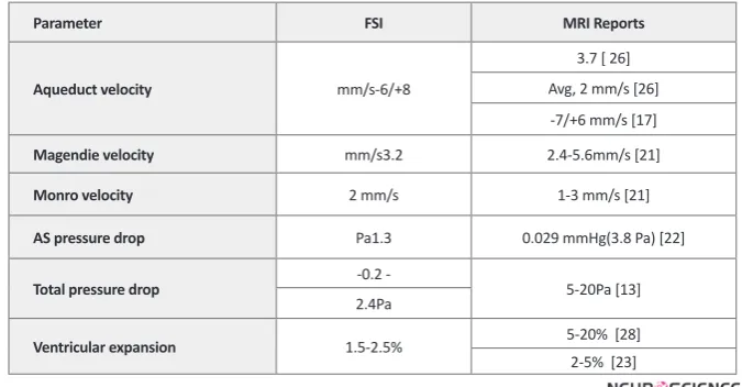
Table 3. Comparison of the results of FSI model and MRI experiments.
Parameter FSI MRI Reports
Aqueduct velocity mm/s-6/+8
3.7 [ 26] Avg, 2 mm/s [26] -7/+6 mm/s [17]
Magendie velocity mm/s3.2 2.4-5.6mm/s [21]
Monro velocity 2 mm/s 1-3 mm/s [21]
AS pressure drop Pa1.3 0.029 mmHg(3.8 Pa) [22]
Total pressure drop -0.2 - 5-20Pa [13]
2.4Pa
Ventricular expansion 1.5-2.5% 5-20% [28]
2-5% [23]
Table 4. Comparison of the results between our FSI model and published model
(for positive the flow is toward outlet and negative in reverse).
Models Aqueduct Velocity As Pressure Drop Total Pressure Drop
Linninger [13] +12.8/-12.9 mm/s - 6 Pa
Jacobson [6] +23 mm/s 2 Pa 3-10 Pa
Fin [8] 22 mm/s 0.6-10 Pa
-Kurtcuoglu [11] -25/+11 mm/s 20 Pa
The pulsatile CSF motion is induced by the CSF gen-eration from the choroid-plexus in the ventricles. The importance of CSF pulsatile behavior has been dis-cussed in previous studies (Miyati et al., 2007; Ye & Bogaert, 2008).Zhuhave indicated that the growth of the vascular bed in the systole resultsinsolidity of the lateral ventricle andswelling of the choroid-plexus
lead-ing to CSF-flow out of the ventricles (Hofmann, War -muth-Metz, Bendszus, & Solymosi, 2000). In a recent study,Linningerdeveloped the CSF pulsatile formation equation considering underlying arterial pulsation syn-chronized with heart beat(Ursino, 1988). Regarding his
idea, we have studied the influence of pulsation in our
model by considering a CSF pulsatile formation.
The objective of the current study was to ascertain the velocity characteristics of CSF and CSF pressure dis-tribution in HVS. In fact, the pressure in HVS region is ICP. However,in our modeling we considered zero pres-sure at the passage of the fourth-ventricle. Therefore, the pressure distribution in HVS was obtained relative to actual outlet pressure. The publishedMRI results are also included in Table IVfor comparison.
Comparing the results of rigid and FSI conditions shows that velocity magnitude and pressure drop is about half time when the tissue effects were included. As the CSF passes through the HVS, a portion of its kinetic energy will be consumed to deform the elastic ventricular walls and consequently the surrounding tis-sue and will be saved there as a potential energy. This is also the reason for velocity differences in rigid and deformable models in contact with solid. Moreover, our FSI model is capable of predicting the LV wall displace-ment obtained in cine MRI studies. In our modeling, the lateral ventricle enlargement is in good agreement with the published MRI results (Nitz et al., 1992)(Hofmann et al., 2000) (Table III).The pressure drop of not more than 10Pa obtained by Jacobson and later by Aroussiis in good agreement with our results. However, the veloc-ity results show an observable difference. 2D modeling of Linninger(Ursino, 1988) declares the velocity
mag-nitude of 12mm/s in aqueduct and 4 mm/s in Magendie
foramina. Our FSI model showsa relatively smaller ve-locity.
As can be seen from the pressure contour, the pressure varies through the HVS with the greatest pressure drop occurring through the aqueduct, due to higher dynamic pressure caused by large CSF velocity in this region.
In the FSI model we obtained 8 mm/s for maximum
velocity value and 1.2Pa for pressure drop of the
aq-ueduct region, which is consistent with the findings of
Jacobson who showed that a pressure drop of 1.1 Pa is
necessary to drive the flow of higher CSF production
through the aqueduct. Not only the velocity and
pres-sure distribution magnitude but also the flow diagram is
in good agreement with the MRI observation. As seen
in Fig. 6, the flow reverses from the 4th ventricle toward
the 3rd ventricle in diastolic time. Clinical evidence also validates that the CSF-motion in the AS reverses with each cardiac sequence(Ursino, 1988)(Nitz et al., 1992) (Zhu et al., 2006)(Hofmann et al., 2000) whilst the arte-rial as well as venous-blood pressure disparity is for all
time positive. The event can be justified with the en -ergy storage in brain tissue. The outcome is the return of
elastic tissue twist of the ventricular-wall so fluid-flow
reverses (Ursino, 1988)(Hofmann et al., 2000). As the cardiac-cycle goes through diastole, pressure falls in the
cranium leading to flow of CSF from the spinal-SAS up
into the cerebral-SAS and backside into the ventricles (Sivaloganathan et al., 1998).
There is a hypothesis that arteriolar pulsation in the parenchyma is the main cause for ventricular wall dis-placement and this disdis-placement induces the CSF pul-satile motion (Balédent et al., 2004). In this article, we consider the effect of arteriolar pulsation responsible for
the pulsatile CSF flow in HVS (Ursino, 1988)(Nitz et
al., 1992) This fact, in addition to elastic brain tissue
interaction on CSF flow, produces the diastolic back flow and causes the ventricular wall displacement in the
boundary of Solid-Fluid. We have shown that the ven-tricular wall displacement could be a passive result due to the pulsatile motion. As Grietz and Egnor(Nitz et al., 1992) and also the famous Bering (Miller, 1999) experi-ments have shown the pulsation should be applied to the CSF formation process from the choroid. This phe-nomenon was called “a kind of fourth circulation” by Madson. .
Also, the MRI results show that there is a phase dif-ference between the CSF velocity which is considered synchronized with heart beat and the LV wall displace-ment (Ursino, 1988)(Gu et al., 2012). This fact, which is observable in our result as well(Fig. 9 (b,c)), validates our hypothesis which is based on CSF pulsatile genera-tion as a driving force and the LV displacement as a pas-sive result for the incident.
Mezrich, 1989)(Gu et al., 2012) or the theoretical mod-el of Linninger(Ursino, 1988) which obtained 4-4.5% ventricular expansion for lateral ventricles. This large difference was perhaps due to their approximation of brain tissue effect while our modeling includes the real
effect of elastic tissue. Our work confirms the impor
-tance of pulsatility of inflow and also the interaction
of solid phase by comparing the FSI model and a rigid one with real MRI data (Ursino, 1988)(Nitz et al., 1992) (Hofmann et al., 2000).
Though 2D models provide a quantitative simulation
of CSF flow in the ventricles, the qualitative results pro -vided through such models are more reliable. A more realistic 3D model of HVS geometry though seems to yield more accurate results, is a complex and cumber-some task which has not been seen in recent literature.
We propose that CSF flow and interaction of the paren -chyma to be modeled in a 3D pattern for future studies. Another shortcoming in our modeling is that the brain parenchyma is treated as an elastic material, causing the ventricular walls to return to their previous position af-ter each pulsation. However, as the work of Miller and coworkers (Yoo et al., 2012) has shown, the mechani-cal behavior of the brain tissue is more appropriately explained with visco-elastic or non-linear hyper elastic models. Another probable pitfall in our 2D model is that the SAS chamber and diffusion of CSF into the venous sinuses has not been considered, which does not seem to be a major obstacle considering the recent advances in CFD software package. Efforts are underway to ex-tend the model presented here in to a 3D model of brain ventricle, SAS and parenchyma, capable of describing the absolute pressure in HVS system. Also we have not considered brain arterial pulsations in our model. The effect of this can be considered for future study.
References
Balédent, Olivier, Gondry-Jouet, Catherine, Meyer, Marc-Etienne, De Marco, Giovanni, Le Gars, Daniel, Henry-Feu-geas, Marie-Cécile, & Idy-Peretti, Ilana. (2004). Relation-ship Between Cerebrospinal Fluid and Blood Dynamics in Healthy Volunteers and Patients with Communicating Hy-drocephalus. Investigative Radiology, 39(1), 45-55.
Benitah, Salvador Aznar. (2012). Defining an epidermal stem
cell epigenetic network. Nat Cell Biol, 14(7), 652-653.
Chopp, Michael, & Portnoy, Harold D. (1980). Systems analysis of intracranial pressure. Journal of Neurosurgery, 53(4), 516-527. doi: doi:10.3171/jns.1980.53.4.0516
Goldsmith, W. (2001). The state of head injury biomechanics: past, present, and future: part 1. Critical reviews in biomedi-cal engineering, 29(5-6), 441-600.
Greitz, Dan. (2004). Radiological assessment of hydrocephalus: new theories and implications for therapy. Neurosurgical Review, 27(3), 145-165. doi: 10.1007/s10143-004-0326-9
Gu, Ben J., Duce, James A., Valova, Valentina A., Wang, Bruce, Bush, Ashley I., Petrou, Steven, & Wiley, James S. (2012). The P2X7-mediated scavenger activity of mononuclear phago-cytes towards non-opsonized particles and apoptotic cells is inhibited by serum glycoproteins but remains active in
cerebrospinal fluid. Journal of Biological Chemistry. doi:
10.1074/jbc.M112.340885
Hofmann, Erich, Warmuth-Metz, Monika, Bendszus, Martin, & Solymosi, Lászlò. (2000). Phase-Contrast MR Imaging of the Cervical CSF and Spinal Cord: Volumetric Motion Anal-ysis in Patients with Chiari I Malformation. American Jour-nal of Neuroradiology, 21(1), 151-158.
Jacobson EE, Fletcher DF, Morgan MK, Johnston IH. (1996a). Fluid Dynamics of the Cerebral Aqueduct. Pediatr Neuro-surg, 996;24:229–236(10.1159/000121044).
Jacobson EE, Fletcher DF, Morgan MK, Johnston IH. (1996b). Fluid Dynamics of the Cerebral Aqueduct. Pediatr Neuro-surg, 1996;24:229(236).
Jones, Claire F., Newell, Robyn S., Lee, Jae H.T., Cripton, Pe-ter A., & Kwon, Brian K. (9000). The Pressure Distribution of Cerebrospinal Fluid Responds to Residual Compression and Decompression in an Animal Model of Acute Spi-nal Cord Injury. Spine, Publish Ahead of Print, 10.1097/ BRS.1090b1013e31826ba31827cd.
Kaczmarek, Mariusz, Subramaniam, Ravi, & Neff, Samuel. (1997). The hydromechanics of hydrocephalus: Steady-state solutions for cylindrical geometry. Bulletin of Mathematical Biology, 59(2), 295-323. doi: 10.1007/bf02462005
Lee, E, Wang, J Z, & Mezrich, R. (1989). Variation of lateral ventricular volume during the cardiac cycle observed by MR imaging. American Journal of Neuroradiology, 10(6), 1145-1149.
Marmarou, Anthony, Shulman, Kenneth, & Rosende, Roberto
M. (1978). A nonlinear analysis of the cerebrospinal fluid
system and intracranial pressure dynamics. Journal of Neu-rosurgery, 48(3), 332-344. doi: doi:10.3171/jns.1978.48.3.0332
Meier, U., Zeilinger, F. St, & Kintzel, D. (1999). Diagnostic in Normal Pressure Hydrocephalus: A Mathematical Model for Determination of the ICP-Dependent Resistance and Com-pliance. Acta Neurochirurgica, 141(9), 941-948. doi: 10.1007/ s007010050400
Miller, Karol. (1999). Constitutive model of brain tissue
suit-able for finite element analysis of surgical procedures.
Journal of Biomechanics, 32(5), 531-537. doi: 10.1016/s0021-9290(99)00010-x
Nitz, W R, Bradley, W G, Watanabe, A S, Lee, R R, Burgoyne, B, O'Sullivan, R M, & Herbst, M D. (1992). Flow dynamics of
cerebrospinal fluid: assessment with phase-contrast velocity
MR imaging performed with retrospective cardiac gating. Radiology, 183(2), 395-405.
Patrachari, Anirudh R., Podichetty, Jagdeep T., & Madihally,
Sundararajan V. (2012). Application of computational fluid
dynamics in tissue engineering. Journal of Bioscience and Bio-engineering, 114(2), 123-132. doi: 10.1016/j.jbiosc.2012.03.010
Sivaloganathan, S., Tenti, G., & Drake, J. M. (1998).
Mathemati-cal pressure volume models of the cerebrospinal fluid. Ap -plied Mathematics and Computation, 94(2–3), 243-266. doi: 10.1016/s0096-3003(97)10093-5
Ursino, Mauro. (1988). A mathematical study of human in-tracranial hydrodynamics part 2—Simulation of clinical tests. Annals of Biomedical Engineering, 16(4), 403-416. doi: 10.1007/bf02364626
Ursino, Mauro, & Lodi, Carlo Alberto. (1997). A simple math-ematical model of the interaction between intracranial pres-sure and cerebral hemodynamics. Journal of Applied Physi-ology, 82(4), 1256-1269.
Whyte, Warren A., Bilodeau, Steve, Orlando, David A., Hoke, Heather A., Frampton, Garrett M., Foster, Charles T., . . . Young, Richard A. (2012). Enhancer decommis-sioning by LSD1 during embryonic stem cell differentia-tion. Nature, 482(7384), 221-225. doi: http://www.nature. com/nature/journal/v482/n7384/abs/nature10805. html#supplementary-information
Ye, Yuxiang, & Bogaert, Jan. (2008). Cell therapy in myocardial infarction: emphasis on the role of MRI. European Radiol-ogy, 18(3), 548-569. doi: 10.1007/s00330-007-0777-9
Yoo, Kyung, Kim, Seok, Chung, Sung, Jeong, Cheol, Jeong, Seong, Curia, Luciana, . . . Murthy, Hanuman K. (2012). CLINICAL NEUROSCIENCES / Paper No:
40.00Dose-re-lated Reduction of Sevoflurane Requirements to Block Auto
-nomic Hyperreflexia by Remifentanil During Transurethral
Litholapaxy in Patients with High Complete Spinal Cord In-jury / Paper No: 79.00DIC and Venous Air Embolism during surgical resection of a Giant Meningioma. A case report / Paper No: 155.00Anaesthetic implications for intraoperative
high field magnetic resonance imaging in neurosurgery: our
experience / Paper No: 296.00Intrathecal baclofen for spas-ticity and pain / Paper No: 297.00Arixtra (Fondaparinux) as Part of Treament for Patients with Stroke / Paper No: 340.00Cerebral Desaturation Events During Beach Chair Position Shoulder Surgery: Regional Versus General Anes-thesia / Paper No: 403.00The relationship between shivering and opioid-induced hyperalgesia induced by high doses of remifentanil in patients undergoing single port gynecologic surgeries / Paper No: 514.00Respiratory support in acute brain injury / Paper No: 542.00To study the incidence and characteristics of postoperative complications during hos-pital stay in patients undergoing transsphenoidal removal of pituitary tumors / Paper No: 841.00Respiratory compli-cations in the early postoperative period following elective craniotomies / Paper No: 926.00Diagnostic and prognostic importance disoders purine metabolism in acute cerebral ischemia / Paper No: 936.00Early extubation after pro-longed intracraneal tumour surgery in children / Paper No: 1090.0Thalamocortical networks participate in propofol-in-duced unconsciousness: a functional imaging study / Paper No: 1092.0Comparison of preexisting cognitive impairment, amnestic mild cognitive impairment, and multiple domain
mild cognitive impairment in men scheduled for coronary artery surgery / Paper No: 1192.0Meta-Analysis on the Ac-curacy of Neuromonitoring in Awake Patients undergoing Carotid Endarterectomy / Paper No: 1222.0 Glasgow Coma Score in Patients with Severe Traumatic Brain Injury with or without Intracranial Pressure Monitoring / Paper No: 1234.0 Clonidine vs dexmeditomidine in intracranial tumor surger-ies: comparison of haemodynamic stability, brain relaxation and emergence. British Journal of Anaesthesia, 108 (suppl 2), ii65-ii74. doi: 10.1093/bja/aer476
Zhu, David C., Xenos, Michalis, Linninger, Andreas A., & Penn, Richard D. (2006). Dynamics of lateral ventricle and
cerebrospinal fluid in normal and hydrocephalic brains.