Research Journal
Volume 11, Iss. 1, March 2017, pages 212–219
DOI: 10.12913/22998624/68458 Research Article
CNG INJECTOR RESEARCH FOR DUAL FUEL ENGINE
Adam Majczak1, Grzegorz Barański1, Ksenia Siadkowska1, Rafał Sochaczewski2
1 Lublin University of Technology, Faculty of Mechanical Engineering, Lublin, Poland, e-mail: a.majczak@pollub. pl, g.baranski@pollub.pl, k.siadkowska@pollub.pl
2 Pope John Paul II State School of Higher Education in Biała Podlaska, Biała Podlaska, Poland, e-mail: r.sochaczewski@pollub.pl
ABSTRACT
The article presents the tests results of the prototype design of hydraulically assisted injector that is designed for gas supply into diesel engines. The construction of the injector allows for its positioning in the glow plug socket, so that the gas is injected directly into the combustion chamber. The cycle analysis of the four-cylinder Andoria ADCR engine with a capacity of 2.6 dm3 for different crankshaft rotational speeds allowed to determine the necessary time for fuel injection. Because of that, it was
pos-sible to determine the required mass flow rate of the injector, for replacing as much of the original fuel by gaseous fuel. To ensure a high value of flow inside the injec -tor, supply pressure equal to 1 MPa was applied. High gas supply pressure requires high value of valve opening forces. For this purpose a injector with hydraulic control system, using a liquid under pressure for the opening process was designed. On the
basis of air pressure measurements in the flow line after the injector, the analysis of opening and closing of the valve was made. Measurements of outflow mass of the
injector were also carried out. The results showed that the designed injector meets the requirements necessary to supply ADCR engine with CNG fuel.
Keywords: CNG, diesel, gas flow, gas injector, dual fuel.
INTRODUCTION
Constantly rising oil prices and environmen-tal considerations necessitate the search for new energy sources. One of the available solutions is a partial replacement of diesel fuel by compressed natural gas (CNG) in the compression ignition engines. This type of the engines is used mainly in vans and trucks. These units are also gaining more and more popularity in the passenger car market. In Europe, this part of the market share reaches 50%. Diesel engines are also used in in-dustry in such means of transport as ship or loco-motives. Diesel engines have higher emissions of nitrogen oxides in comparison to spark ignition engines. This can be currently limited by optimiz-ing the combustion process and the use of addi-tional systems, such as exhaust gas recirculation
or AdBlue technology. As a result of the combus-tion process of diesel fuel also particulate mat-ter (PM) that are harmful to the human health are emitted. Their emission is limited by the use of a
particulate filter.
One of the method for reducing toxic compo-nents emission may be the use of liquid gas fuel, such as propane and butane (LPG) or compressed natural gas (CNG). In addition to the environ-mental aspects, there are also economic reasons for the use of gaseous fuels to power diesel en-gines [1, 4, 6]. A total or partial replacement of diesel gas is possible. Depending on the used technology and the percentage of diesel fuel re-placement it is possible to reduce the content of nitrogen oxides in the exhaust gas even by 30%, particulate matter (PM) by 95% carbon monoxide and by 20%, in relation to original diesel fuel [3]. Received: 2016.12.15
The use of gas fuel in the diesel engine is much more complicated than in spark-ignition engines. For engines with indirect fuel injec-tion, which currently represent the majority of the market, the installation of gas injectors in the inlet manifold and system calibration is only necessary for the conversion. Currently, engines with direct petrol injection are becoming more and more popular. In such engines it is much
more difficult to carry out the conversion process
to supply engine with the gas fuel, due to lack of space for gas injectors mounted in the cylinder head. Originally mounted gasoline fuel injectors also require cooling process which forces them to work from time to time.
Adaptation of the diesel engine for supply with the gas fuel is associated with similar prob-lems. Additionally, because diesel engines are not equipped with an ignition device (spark plug in the spark ignition engine), when the lack of gas self-ignition ability occurs, there is a need to mount additional components such as spark plugs or to use a pilot dose of diesel fuel in order to ini-tiate the combustion of the mixture [5]. In diesel engines there is also a no quantitative adjustment of injection, which causes the situation that for small engine loads the mixture is too lean, which prevents it from burning while for a high engine loads to rich mixture can leads to a knock combus-tion. Thus, from the technical point of view, the conversion of the diesel engine and its adaptation for gas fuel supply can be expensive and compli-cated. Nowadays, diesel engines are most often
converted in two different ways. The first way is
to adapt the engine to the process which occurs in a spark-ignition engine. In place of diesel fuel in-jectors, spark plugs are mounted, the compression ratio must be changed and the intake system must be equipped with a throttle. To ensure toxic emis-sions at an appropriately low level, three way cat-alytic converter must be mounted in the exhaust system. With this kind of changes the diesel en-gine becomes a spark-ignition enen-gine. Changing
the thermodynamic cycle results in a significant
decrease in engine performance. The moderniza-tion carried out in such a way is very expensive
and economically unjustified.
The diesel engine conversion may be also carried out without interfering with the structure of the engine. In this case, the gas fuel is burned together with original diesel fuel in the dual fuel mode. Indirect gas injection into the intake manifold or in the more sophisticated systems,
direct injection into the combustion chamber can be used. Indirect injection system is consider-ably less complicated, unfortunately, it has some disadvantages, such as the occurrence of knock combustion and high emissions of exhaust tox-ic components resulting from the fact that part of the fuel entered into the exhaust pipe during the induction process. This is due to a long time of valves overlap, that is used in compression ignition engines. The best option in terms of economic, environmental and technical is the direct injection of gas fuel into the combustion chamber of the engine. In such systems, the gas is injected at high pressure at the end of the in-duction phase. This makes it possible to remove the remain exhaust gases from the cylinder and
to obtain a high degree of cylinder filling with
fresh air. Ignition is initiated by the pilot diesel fuel injected dose to the combustion chamber at the end of the compression stroke, while the main fuel is a gas. In the bibliography you can
find many research results describing the opera -tion of the diesel engine in dual fuel mode. The
influence of the percentage use of the gas to the
change of performance and toxic components emissions is described [4]. There are also stud-ies showing the impact of pilot dstud-iesel fuel dose angle injection on the engine performance [1]. Due to the change in the type of fuel, diesel fuel injection angle correction, which initiates air-gas mixture combustion is required.
The article presents the concept of the injec-tor for the direct injection of compressed natural gas (CNG).
RESEARCH OBJECT
The research object is a prototype gas injector designed for direct injection of compressed natural gas (CNG) in compression ignition engines. The design of the injector allows to place it in the glow
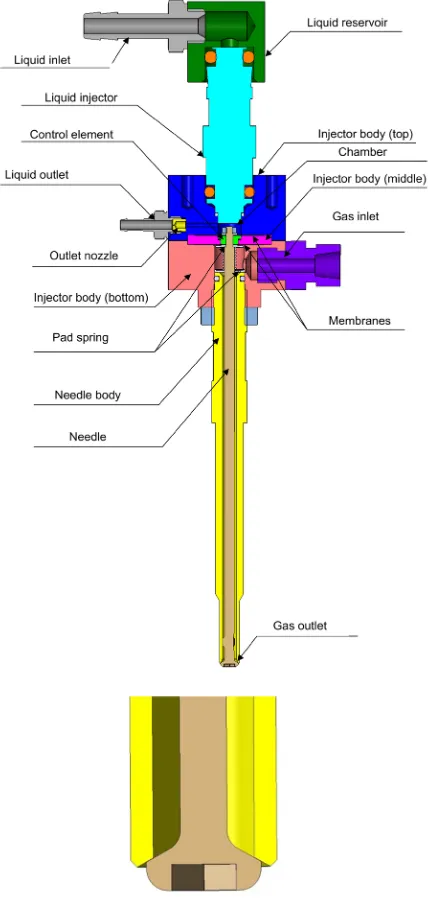
plug socket which significantly simplifies installa -tion, so it is unnecessary to change the engine com-ponents. In order to ensure proper engine start-up parameters after removal of the glow plugs it is necessary to equip the engine with a device to heat the intake air. Other systems mounted in the engine do not require any changes. The presented injector conception is based on a hydraulic controlling of opening and closing process of the injector valve. Injector needle is the element that controls the gas
-tion of the engine valve. When the injector valve is closed the needle is contacting with the needle
body thereby blocking the gas flow. Contact area
of the needle and the body must be made with the accuracy ensuring tightness of connection. The needle body and the needle has been designed in such a way that it was possible to mount the injec-tor in a standard glow plug socket. The glow plugs normally are located in the combustion chamber located in the piston which cause that the glow
plugs have a significant length.
Developed construction of the injector allows screwing it into the socket of the glow plug while the injector body is located out of the cylinder
head, what enables the free flow of gas from the
injector into the combustion chamber. For better illustration of the location of the injector, the en-gine head model is presented in Figure 1. The nee-dle in its upper part is connected with the control element. Opening of the injector is performed by
filling the chamber located above the control ele -ment with a liquid. Increasing liquid pressure in the chamber causes the control element movement in the direction of the valve which leads to the needle movement from the needle body and the
gas flow from the injector. The liquid flow from a
chamber located above the control element is pro-vided by a calibrated nozzle located in the injector body. The nozzle diameter determines velocity of
opening and closing of the injector. For filling the
liquid chamber a commercially available Bosch PFI liquid injector that is electromagnetically-controlled was used. Gas and liquid injectors are separated from each other by a rubber membrane which provides seal and allows for movement of
the injector needle along its axis. Designed injec-tor is characterized by the possibility of obtaining a large needle lift, and the generation a high valve opening forces, which depends on the control ele-ment surface from the liquid chamber. The value of the injector opening force can be adjusted by changing the control element diameter. In addi-tion, spring assisting valve closing is mounted in the injector body. A complete model of the injector and inceptor tip is shown in Figure 2. The control element, and the maximum height of the needle lift are shown in Figure 3. Needle lift regulation is provided by the regulation of distance between needle body and injector body. All the compo-nents of the actual injector are shown in Figure 4. Fig. 1. The injector location in the cylinder head
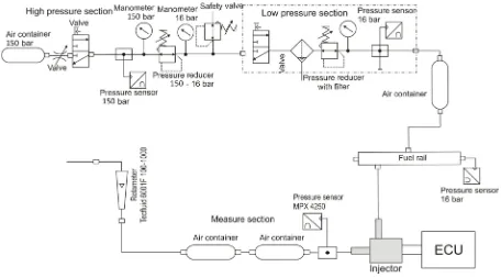
TEST STAND
Tests were performed on a test stand de-signed to determine the characteristics of the gas injectors shown in Figure 5. The test stand consisted of air preparation system which in-cludes: compressed air cylinders (15 MPa), the initial pressure reducer (1.6 MPa), the second
stage pressure regulator with filter allowing
for precise adjustment of air pressure and air
accumulator limiting pressure pulsations. Air preparation system is connected to the fuel rail and then to the tested injector. At each of the air preparation stages, pressure value registra-Fig. 3. Control element, maximum stroke and
calibrated nozzle
Fig. 4. Components of the injector
tion is possible. At the outlet of the injector, a MPX 4250 pressure sensor with a measuring range from 0 to 0.25 MPa of absolute pressure is mounted. This sensor is designed for fast changing measurements, which allows to spec-ify the time of opening and closing of the
injec-tor. Injector mass flow measurement is carried
out in section consisting of the rotameter and two air accumulators to restrict the air pressure pulsations. Control of the injector is realized by the control unit which allows for control of the liquid injector with any frequency and duration of the injection pulse. In addition, the test stand was equipped with a Tektronix TCP305 current
probe with TCPA300 amplifier for determining
the current value in the liquid injectors coil. All sensors and measuring elements were supplied with stabilized energy sources.
RESEARCH OBJECTIVE AND SCOPE
The aim of this study was to determine the
flow characteristics of the hydraulically assisted
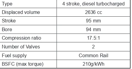
injector. An analysis was conducted on the time available for injection in a 4-cylinder, Andoria ADCR turbocharged compression ignition en-gine equipped with a diesel common rail fuel in-jection system. The manufacturer of the engine is a Polish company Andoria-Mot Sp. with o.o. The main engine parameters are: displacement 2636 cm3, maximum power of 85kW at 3700 rpm and
torque of 250 Nm at 1800-2200 rpm. The engine meets the Euro 4 emissions standards.
Basic engine parameters are presented in ta-ble 2. Engine was originally equipped with glow plugs placed in the engine head so that it was pos-sible to replace them by specially designed injec-tors. In order to accurately determine the time at which the gas will be injected it was necessary to determine the valve timing of the engine. Timing diagram is shown in Figure 6. To fully realize di-rect injection into the cylinder, the injection must begin after the closing of the exhaust valve, after the end of valves overlap. In this way, the phe-nomenon of fuel entry into the exhaust manifold was eliminated. Maximum time in which the gas can be injected depends on the engine crankshaft rotational speed. This engine is characterized by a crankshaft rotational speed within a range from 750 rpm (idle speed) to 3800 rpm. Because of that, the duration of a complete cycle is between 12.5 ms and 68 ms.
The maximum fuel injection time according to the engine rotational speed is shown in Figure 7. This calculation allowed the determination of the required gas amount needed for the imple-mentation of the engine working cycle, depend-ing on the degree of substitution of the original fuel. For Andoria ADCR engine adopted to the supply by a gas, 31mg must be provided for a 20% and 165.6 mg for a 100% replacement of the original diesel fuel. It means that the gas fuel need
to be injected with the mass flow rate in the range
of 0.87-12.38 mg/ms. Due to prototype version of the gas injector tests were carried out at a pressure value equal to 1 MPa.
Higher pressure values could lead to the de-struction of the membrane separating the spaces
filled with liquid and gas. Injection time was de -termined from the minimum value for which it was possible to observe the valve opening pro-cess, up to 8ms. Measurements were taken for
four different liquid calibrated nozzles which diameters ranged from 0.2-0.5 mm. Injector flow rate was measured as air flow by using a rotame -ter and then this value was converted to a mass
flow rate of the one injection process. Using the calculation coefficients, these values were calcu -lated on the mass of the injected fuel in the case of
Table 1. Test conditions
Injection pressure (gas) 1 MPa (diff.)
Liquid injector PFI BOSCH
Liquid injection pressure 0,6 MPa
Injector needle stroke 0,3 mm
Outlet nozzle diameter 0,2 – 0,5 mm
Injection time 2 – 8 ms
Operating voltage (PFI Injector) 12 V Operating current (PFI Injector) constant Back pressure after injector 0,1 MPa
Injection frequency 15 Hz
Table 2. ADCR engine parameters
Type 4 stroke, diesel turbocharged
Displaced volume 2636 cc
Stroke 95 mm
Bore 94 mm
Compression ratio 17.5:1
Number of Valves 2
Fuel supply Common Rail
CNG using. Also, the time of opening and closing was analyzed, based on the pressure at the outlet of the injector. In the described case, it is not pos-sible to measure the opening time of the injector by a vibration sensor [2]. Due to a completely dif-ferent character of the valve opening as compared to a solenoid controlled injectors, it is not possi-ble to determine the vibration characteristics and thereby the moment of full opening of the valve.
RESEARCH RESULTS
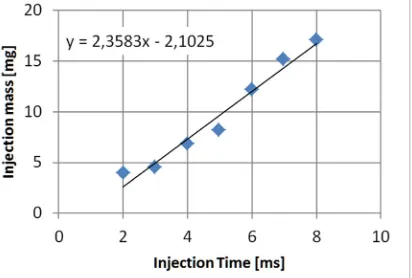
The research results were the injector flow
characteristics as a function of injection time. During the study very large valve opening delay more than 3 ms was found. This is due to the long
time of filling the pressure chamber and a contin
-uous liquid outflow through the outlet calibrated nozzle. The flow rate characteristics of the injec -tor was also made. The needle lift was set at 0.3 mm (3,42 mm2 opening area). The characteristics
of the injector depending on the used nozzle are
shown in Figures 8-11.The injection mass was
measured by calculating volume flow during the
injections with constant frequency to one injec-tion. Increasing of the nozzle diameter results in a lengthening of the injector opening time and
a decrease in mass flow. The flow rate analysis
of the injector showed a decrease with increase of nozzle diameter (Fig. 12). The analysis of the valve opening time and the closing time was pos-sible due to the fast registration of the air pres-sure value after the injector. In Figure 13 an ex-emplary characteristics of pressure measurement
after the injector outflow, current in the circuit
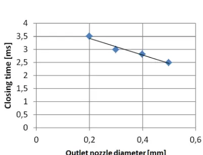
of the liquid injector and a method for determin-ing the delay of the valve opendetermin-ing and closdetermin-ing were shown. Time dependence of opening and closing of the valves, depending on the diameter of the outlet nozzle is shown in Figures 14-15. The nozzle diameter increasing extends the valve opening time, but decreases its closing time. The method of determining opening and closing time was described by [2].
Fig. 6. ADCR engine valve timing
Fig. 7. Cycle duration and the maximum injection time
Fig. 8. Injector mass flow characteristics for 0.2 mm
outlet nozzle (Injection pressure 1 MPa)
Fig. 9. Injector mass flow characteristics for 0.3 mm
Fig. 10. Injector mass flow characteristics for 0,4mm
outlet nozzle (Injection pressure 1MPa)
Fig. 11. Injector mass flow characteristics for 0,5mm
outlet nozzle (Injection pressure 1 MPa)
Fig. 12. Relation between injection flow rate and
outlet nozzle diameter (Injection pressure 1 MPa)
Fig. 13. Mean time course of measured values and
method of definitions of opening
and closing delay time
Fig. 14. Relation between injection opening delay time and outlet nozzle diameter
(Injection pressure 1 MPa)
Fig. 15. Relation between injection closing delay time and outlet nozzle diameter (Injection pressure 1 MPa) In none of the examined cases, the opening
time is equal to the closing time, this is why the intersection point of the injector characteristics does not intersect with the X axis in the zero point. In the use of a nozzle with a diameter of
0.2 mm, a significant delay in valve closing can
be observed, what is caused by the small intensity
liquid outflow. The difference between the time
CONCLUSIONS
As a result of bench tests and comparing the results obtained from the analysis of the require-ments for the gas supply in the presented en-gine, it can be held that, an injector is not able to provide a partial replacement of diesel fuel in the whole range of engine operation
condi-tions, because a large mass flow is required to in
-ject necessary dose of gas. Mass flow reduction
through the injector nozzle is caused by the small nozzle cross-section area which results from the needle lift. The construction of the injector does not allows to increase the maximum needle lift more than 0.3 mm. Long time of valve opening
is caused by a delay of filling the liquid cham
-ber caused by too little fluid injector flow. Both,
the times of opening and closing of the valve
de-pends on the fluid injector nozzle diameter. De -veloped injector design that takes into account the changes to reduce the delay of valve opening and
closing, and to increase outflow, can be used for
further research both on the test bench and in the real world condition in the engine test bench. The described construction of the gas injector due to the very wide range of control parameters such as the force acting on the needle or needle lift , after
the necessary modifications, can be used to sup -ply diesel engines with compressed natural gas or other similar fuel.
Acknowledgments
This work has been financed by the Polish
National Centre for Research and Development, under Grant Agreement No. PBS1/A6/4/2012.
REFERENCES
1. Barata J.M.M. Performance and Emissions of a Dual Fueled DI Diesel Engine. SAE Technical Pa-per, Series 952364, 1995.
2. Czarnigowski J., Barański G., Wendeker M., Duk
M., Zyska T. Method to measure injector opening and closing lag times. Combustion Engines, 2011, 50 (1), 20–28.
3. Kajiwara M., Sugiyama K., Sagara M., Mori M., Goto S., Alam. M. Performance and Emissions Characteristics of an LPG Direct Injection Diesel Engines. SAE Technical Paper, Series 2002-01-0869, 2002.
4. Saleh H.E. Effect of variation in LPG composition
on emissions and performance in a dual fuel diesel engine. Fuel 87, 2008, 3031–3039.
5. Stelmasiak, Z. Selected problems of application of natural gas to CI engine. Archiwum Motoryzacji, 2006.