CHAPTER 1 INTRODUCTION 1
INTRODUCTION
1
1.1 Overview
Computer architecture deals with the functional behavior of a computer system as viewed by a programmer. This view includes aspects such as the sizes of data types (e.g. using 16 binary digits to represent an integer), and the types of opera-tions that are supported (like addition, subtraction, and subroutine calls). Com-puter organization deals with structural relationships that are not visible to the programmer, such as interfaces to peripheral devices, the clock frequency, and the technology used for the memory. This textbook deals with both architecture and organization, with the term “architecture” referring broadly to both architec-ture and organization.
There is a concept of levels in computer architecture. The basic idea is that there are many levels, or views, at which a computer can be considered, from the high-est level, where the user is running programs, or using the computer, to the low-est level, consisting of transistors and wires. Between the high and low levels are a number of intermediate levels. Before we discuss those levels we will present a brief history of computing in order to gain a perspective on how it all came about.
1.2 A Brief History
Mechanical devices for controlling complex operations have been in existence since at least the 1500’s, when rotating pegged cylinders were used in music boxes much as they are today. Machines that perform calculations, as opposed to simply repeating a predetermined melody, came in the next century.
con-2 CHAPTER 1 INTRODUCTION
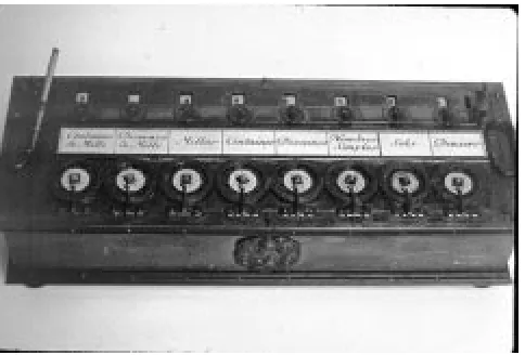
nect to a drum (Figure 1-1), with an innovative linkage that causes a dial to
rotate one notch when a carry is produced from a dial in a lower position. A win-dow is placed over the dial to allow its position to be observed, much like the odometer in a car except that the dials are positioned horizontally, like a rotary telephone dial. Some of Pascal’s adding machines, which he started to build in 1642, still exist today. It would not be until the 1800’s, however, until someone would put the concepts of mechanical control and mechanical calculation together into a machine that we recognize today as having the basic parts of a digital computer. That person was Charles Babbage.
Charles Babbage (1791 – 1871) is sometimes referred to as the grandfather of the computer, rather than the father of the computer, because he never built a practi-cal version of the machines he designed. Babbage lived in England at a time when mathematical tables were used in navigation and scientific work. The tables were computed manually, and as a result, they contained numerous errors. Frus-trated by the inaccuracies, Babbage set out to create a machine that would com-pute tables by simply setting and turning gears. The machine he designed could even produce a plate to be used by a printer, thus eliminating errors that might be introduced by a typesetter.
Babbage’s machines had a means for reading input data, storing data, performing calculations, producing output data, and automatically controlling the operation of the machine. These are basic functions that are found in nearly every modern computer. Babbage created a small prototype of his difference engine, which evaluates polynomials using the method of finite differences. The success of the
CHAPTER 1 INTRODUCTION 3
difference engine concept gained him government support for the much larger
analytical engine, which was a more sophisticated machine that had a mecha-nism for branching (making decisions) and a means for programming, using punched cards in the manner of what is known as the Jacquard pattern-weav-ing loom.
The analytical engine was designed, but was never built by Babbage because the mechanical tolerances required by the design could not be met with the technol-ogy of the day. A version of Babbage’s difference engine was actually built by the Science Museum in London in 1991, and can still be viewed today.
It took over a century, until the start of World War II, before the next major thrust in computing was initiated. In England, German U-boat submarines were inflicting heavy damage on Allied shipping. The U-boats received communica-tions from their bases in Germany using an encryption code, which was imple-mented by a machine made by Siemens AG known as ENIGMA.
The process of encrypting information had been known for a long time, and even the United States president Thomas Jefferson (1743 – 1826) designed a forerunner of ENIGMA, though he did not construct the machine. The process of decoding encrypted data was a much harder task. It was this problem that prompted the efforts of Alan Turing (1912 – 1954), and other scientists in England in creating codebreaking machines. During World War II, Turing was the leading cryptographer in England and was among those who changed cryp-tography from a subject for people who deciphered ancient languages to a subject for mathematicians.
The Colossus was a successful codebreaking machine that came out of Bletchley Park, England, where Turing worked. Vacuum tubes store the contents of a paper tape that is fed into the machine, and computations take place among the vac-uum tubes and a second tape that is fed into the machine. Programming is per-formed with plugboards. Turing’s involvement in the various Collosi machine versions remains obscure due to the secrecy that surrounds the project, but some aspects of his work and his life can be seen in the Broadway play Breaking the Code which was performed in London and New York in the late 1980’s.
4 CHAPTER 1 INTRODUCTION
18,000 vacuum tubes, which make up the computing section of the machine. Programming and data entry are performed by setting switches and changing cables. There is no concept of a stored program, and there is no central memory unit, but these are not serious limitations because all that the ENIAC needed to do was to compute ballistic trajectories. Even though it did not become opera-tional until 1946, after the War was over, it was considered quite a success, and was used for nine years.
After the success of ENIAC, Eckert and Mauchly, who were at the Moore School at the University of Pennsylvania, were joined by John von Neumann (1903 – 1957), who was at the Institute for Advanced Study at Princeton. Together, they worked on the design of a stored program computer called the EDVAC. A con-flict developed, however, and the Pennsylvania and Princeton groups split. The concept of a stored program computer thrived, however, and a working model of the stored program computer, the EDSAC, was constructed by Maurice Wilkes, of Cambridge University, in 1947.
1.3 The Von Neumann Model
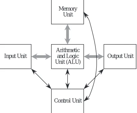
Conventional digital computers have a common form that is attributed to von Neumann, although historians agree that the entire team was responsible for the design. The von Neumann model consists of five major components as illus-trated in Figure 1-2. The Input Unit provides instructions and data to the
sys-Input Unit
Arithmetic and Logic Unit (ALU)
Output Unit Memory
Unit
Control Unit
CHAPTER 1 INTRODUCTION 5
tem, which are subsequently stored in the Memory Unit. The instructions and data are processed by the Arithmetic and Logic Unit (ALU) under the direction of the Control Unit. The results are sent to the Output Unit. The ALU and control unit are frequently referred to collectively as the central processing unit (CPU). Most commercial computers can be decomposed into these five basic units.
The stored program is the most important aspect of the von Neumann model. A program is stored in the computer’s memory along with the data to be pro-cessed. Although we now take this for granted, prior to the development of the stored program computer programs were stored on external media, such as plug-boards (mentioned earlier) or punched cards or tape. In the stored program com-puter the program can be manipulated as if it is data. This gave rise to compilers and operating systems, and makes possible the great versatility of the modern computer.
1.4 The System Bus Model
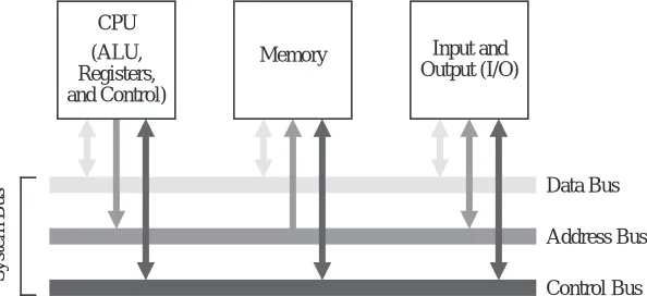
Although the von Neumann model prevails in modern computers, it has been streamlined. Figure 1-3 shows the system bus model of a computer system. This
model partitions a computer system into three subunits: CPU, Memory, and Input/Output (I/O). This refinement of the von Neumann model combines the ALU and the control unit into one functional unit, the CPU. The input and out-put units are also combined into a single I/O unit.
Most important to the system bus model, the communications among the
com-System Bus
Data Bus
Address Bus
Control Bus (ALU,
Registers, and Control)
Memory Input and Output (I/O) CPU
Figure 1-3 The system bus model of a computer system. [Contributed by Donald Chiarulli, Univ.
6 CHAPTER 1 INTRODUCTION
ponents are by means of a shared pathway called the system bus, which is made up of the data bus (which carries the information being transmitted), the
address bus (which identifies where the information is being sent), and the con-trol bus (which describes aspects of how the information is being sent, and in what manner). There is also a power bus for electrical power to the components, which is not shown, but its presence is understood. Some architectures may also have a separate I/O bus.
Physically, busses are made up of collections of wires that are grouped by func-tion. A 32-bit data bus has 32 individual wires, each of which carries one bit of data (as opposed to address or control information). In this sense, the system bus is actually a group of individual busses classified by their function.
The data bus moves data among the system components. Some systems have sep-arate data buses for moving information to and from the CPU, in which case there is a data-in bus and a data-out bus. More often a single data bus moves data in either direction, although never both directions at the same time.
If the bus is to be shared among communicating entities, then the entities must have distinguished identities: addresses. In some computers all addresses are assumed to be memory addresses whether they are in fact part of the computer’s memory, or are actually I/O devices, while in others I/O devices have separate I/O addresses. (This topic of I/O addresses is covered in more detail in Chapter 8, Input, Output, and Communication.)
A memory address, or location, identifies a memory location where data is stored, similar to the way a postal address identifies the location where a recipient receives and sends mail. During a memory read or write operation the address bus contains the address of the memory location where the data is to be read from or written to. Note that the terms “read” and “write” are with respect to the CPU: the CPU reads data from memory and writes data into memory. If data is to be read from memory then the data bus contains the value read from that address in memory. If the data is to be written into memory then the data bus contains the data value to be written into memory.
CHAPTER 1 INTRODUCTION 7
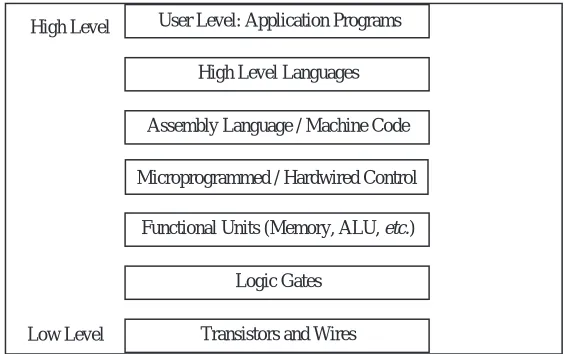
1.5 Levels of Machines
As with any complex system, the computer can be viewed from a number of per-spectives, or levels, from the highest “user” level to the lowest, transistor level. Each of these levels represents an abstraction of the computer. Perhaps one of the reasons for the enormous success of the digital computer is the extent to which these levels of abstraction are separate, or independent from one another. This is readily seen: a user who runs a word processing program on a computer needs to know nothing about its programming. Likewise a programmer need not be con-cerned with the logic gate structure inside the computer. One interesting way that the separation of levels has been exploited is in the development of upwardly-compatible machines.
1.5.1 UPWARD COMPATIBILITY
The invention of the transistor led to a rapid development of computer hard-ware, and with this development came a problem of compatibility. Computer users wanted to take advantage of the newest and fastest machines, but each new computer model had a new architecture, and the old software would not run on the new hardware. The hardware / software compatibility problem became so serious that users often delayed purchasing a new machine because of the cost of rewriting the software to run on the new hardware. When a new computer was purchased, it would often sit unavailable to the target users for months while the old software and data sets were converted to the new systems.
In a successful gamble that pitted compatibility against performance, IBM pio-neered the concept of a “family of machines” with its 360 series. More capable machines in the same family could run programs written for less capable machines without modifications to those programs—upward compatibility. Upward compatibility allows a user to upgrade to a faster, more capable machine without rewriting the software that runs on the less capable model.
1.5.2 THE LEVELS
8 CHAPTER 1 INTRODUCTION
User or Application-Program Level
We are most familiar with the user, or application program level of the computer. At this level, the user interacts with the computer by running programs such as word processors, spreadsheet programs, or games. Here the user sees the com-puter through the programs that run on it, and little (if any) of its internal or lower-level structure is visible.
High Level Language Level
Anyone who has programmed a computer in a high level language such as C, Pascal, Fortran, or Java, has interacted with the computer at this level. Here, a programmer sees only the language, and none of the low-level details of the machine. At this level the programmer sees the data types and instructions of the high-level language, but needs no knowledge of how those data types are actually implemented in the machine. It is the role of the compiler to map data types and instructions from the high-level language to the actual computer hardware. Pro-grams written in a high-level language can be re-compiled for various machines that will (hopefully) run the same and provide the same results regardless of which machine on which they are compiled and run. We can say that programs are compatible across machine types if written in a high-level language, and this kind of compatibility is referred to as source code compatibility.
High Level
High Level Languages User Level: Application Programs
Low Level
Functional Units (Memory, ALU, etc.)
Logic Gates
Transistors and Wires Assembly Language / Machine Code
Microprogrammed / Hardwired Control
CHAPTER 1 INTRODUCTION 9
Assembly Language/Machine Code Level
As pointed out above, the high-level language level really has little to do with the machine on which the high-level language is translated. The compiler translates the source code to the actual machine instructions, sometimes referred to as
machine language or machine code. High-level languages “cater” to the pro-grammer by providing a certain set of presumably well-thought-out language constructs and data types. Machine languages look “downward” in the hierarchy, and thus cater to the needs of the lower level aspects of the machine design. As a result, machine languages deal with hardware issues such as registers and the transfer of data between them. In fact, many machine instructions can be described in terms of the register transfers that they effect. The collection of machine instructions for a given machine is referred to as the instruction set of that machine.
Of course, the actual machine code is just a collection of 1’s and 0’s, sometimes referred to as machine binary code, or just binary code. As we might imagine, programming with 1’s and 0’s is tedious and error prone. As a result, one of the first computer programs written was the assembler, which translates ordinary language mnemonics such as MOVE Data, Acc, into their corresponding machine language 1’s and 0’s. This language, whose constructs bear a one-to-one relationship to machine language, is known as assembly language.
As a result of the separation of levels, it is possible to have many different machines that differ in the lower-level implementation but which have the same instruction set, or sub- or supersets of that instruction set. This allowed IBM to design a product line such as the IBM 360 series with guaranteed upward com-patibility of machine code. Machine code running on the 360 Model 35 would run unchanged on the 360 Model 50, should the customer wish to upgrade to the more powerful machine. This kind of compatibility is known as “binary compatibility,” because the binary code will run unchanged on the various family members. This feature was responsible in large part for the great success of the IBM 360 series of computers.
10 CHAPTER 1 INTRODUCTION
The Control Level
It is the control unit that effects the register transfers described above. It does so by means of control signals that transfer the data from register to register, possi-bly through a logic circuit that transforms it in some way. The control unit inter-prets the machine instructions one by one, causing the specified register transfer or other action to occur.
How it does this is of no need of concern to the assembly language programmer. The Intel 80x86 family of processors presents the same behavioral view to an assembly language programmer regardless of which processor in the family is considered. This is because each future member of the family is designed to exe-cute the original 8086 instructions in addition to any new instructions imple-mented for that particular family member.
As Figure 1-4 indicates, there are several ways of implementing the control unit. Probably the most popular way at the present time is by “hardwiring” the control unit. This means that the control signals that effect the register transfers are gen-erated from a block of digital logic components. Hardwired control units have the advantages of speed and component count, but until recently were exceed-ingly difficult to design and modify. (We will study this technique more fully in Chapter 9.)
A somewhat slower but simpler approach is to implement the instructions as a
microprogram. A microprogram is actually a small program written in an even lower-level language, and implemented in the hardware, whose job is to interpret the machine-language instructions. This microprogram is referred to as firmware
because it spans both hardware and software. Firmware is executed by a micro-controller, which executes the actual microinstructions. (We will also explore microprogramming in Chapter 9.)
Functional Unit Level
CHAPTER 1 INTRODUCTION 11
Logic Gates, Transistors, and Wires
The lowest levels at which any semblance of the computer’s higher-level func-tioning is visible is at the logic gate and transistor levels. It is from logic gates that the functional units are built, and from transistors that logic gates are built. The logic gates implement the lowest-level logical operations upon which the computer’s functioning depends. At the very lowest level, a computer consists of electrical components such as transistors and wires, which make up the logic gates, but at this level the functioning of the computer is lost in details of voltage, current, signal propagation delays, quantum effects, and other low-level matters.
Interactions Between Levels
The distinctions within levels and between levels are frequently blurred. For instance, a new computer architecture may contain floating point instructions in a full-blown implementation, but a minimal implementation may have only enough hardware for integer instructions. The floating point instructions are
trapped† prior to execution and replaced with a sequence of machine language instructions that imitate, or emulate the floating point instructions using the existing integer instructions. This is the case for microprocessors that use optional floating point coprocessors. Those without floating point coprocessors emulate the floating point instructions by a series of floating point routines that are implemented in the machine language of the microprocessor, and frequently stored in a ROM, which is a read-only memory chip. The assembly language and high level language view for both implementations is the same except for execu-tion speed.
It is possible to take this emulation to the extreme of emulating the entire instruction set of one computer on another computer. The software that does this is known as an emulator, and was used by Apple Computer to maintain binary code compatibility when they began employing Motorola PowerPC chips in place of Motorola 68000 chips, which had an entirely different instruction set.
The high level language level and the firmware and functional unit levels can be so intermixed that it is hard to identify what operation is happening at which level. The value in stratifying a computer architecture into a hierarchy of levels is not so much for the purpose of classification, which we just saw can be difficult at times, but rather to simply give us some focus when we study these levels in
12 CHAPTER 1 INTRODUCTION
the chapters that follow.
The Programmer’s View—The Instruction Set Architecture
As described in the discussion of levels above, the assembly language programmer is concerned with the assembly language and functional units of the machine. This collection of instruction set and functional units is known as the instruc-tion set architecture (ISA) of the machine.
The Computer Architect’s View
On the other hand, the computer architect views the system at all levels. The architect that focuses on the design of a computer is invariably driven by perfor-mance requirements and cost constraints. Perforperfor-mance may be specified by the speed of program execution, the storage capacity of the machine, or a number of other parameters. Cost may be reflected in monetary terms, or in size or weight, or power consumption. The design proposed by a computer architect must attempt to meet the performance goals while staying within the cost constraints. This usually requires trade-offs between and among the levels of the machine.
1.6 A Typical Computer System
Modern computers have evolved from the great behemoths of the 1950’s and 1960’s to the much smaller and more powerful computers that surround us today. Even with all of the great advances in computer technology that have been made in the past few decades, the five basic units of the von Neumann model are still distinguishable in modern computers.
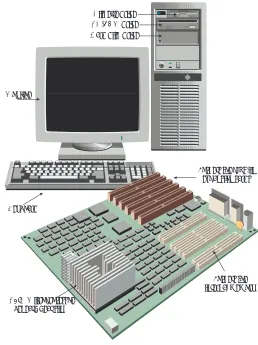
Figure 1-5 shows a typical configuration for a desktop computer. The input unit is composed of the keyboard, through which a user enters data and commands. A video monitor comprises the output unit, which displays the output in a visual form. The ALU and the control unit are bundled into a single micropro-cessor that serves as the CPU. The memory unit consists of individual memory circuits, and also a hard disk unit, a diskette unit, and a CD-ROM (compact disk - read only memory) device.
CHAPTER 1 INTRODUCTION 13
input, output, memory, and ALU/control sections are highlighted as shown. (We will cover motherboard internals in later chapters.)
1.7 Organization of the Book
We explore the inner workings of computers in the chapters that follow. Chapter 2 covers the representation of data, which provides background for all of the chapters that follow. Chapter 3 covers methods for implementing computer arithmetic. Chapters 4 and 5 cover the instruction set architecture, which serves as a vehicle for understanding how the components of a computer interact. Chapter 6 ties the earlier chapters together in the design and analysis of a control
Monitor
CD-ROM drive Hard disk drive
Keyboard
Sockets for internal memory CPU (Microprocessor
beneath heat sink)
Sockets for plug-in expansion cards Diskette drive
14 CHAPTER 1 INTRODUCTION
unit for the instruction set architecture. Chapter 7 covers the organization of memory units, and memory management techniques. Chapter 8 covers input, output, and communication. Chapter 9 covers advanced aspects of single-CPU systems (which might have more than one processing unit). Chapter 10 covers advanced aspects of multiple-CPU systems, such as parallel and distributed architectures, and network architectures. Finally, in Appendices A and B, we look into the design of digital logic circuits, which are the building blocks for the basic components of a computer.
1.8 Case Study: What Happened to Supercomputers?
[Note from the authors: The following contribution comes from Web page http://www.paralogos.com/DeadSuper created by Kevin D. Kissell at [email protected]. Kissell’s Web site lists dozens of supercomputing projects that have gone by the wayside. One of the primary reasons for the near-extinction of
Memory
Input / output
Battery Plug-in expansion card slots
Power supply connector Pentium II processor slot
(ALU/control)
CHAPTER 1 INTRODUCTION 15
supercomputers is that ordinary, everyday computers achieve a significant frac-tion of supercomputing power at a price that the common person can afford. The price-to-performance ratio for desktop computers is very favorable due to low costs achieved through mass market sales. Supercomputers enjoy no such mass markets, and continue to suffer very high price-to-performance ratios.
Following Kissell’s contribution is an excerpt from an Electrical Engineering Times article that highlights the enormous investment in everyday microproces-sor development, which helps maintain the favorable price-to-performance ratio for low-cost desktop computers.]
The Passing of a Golden Age?
From the construction of the first programmed computers until the mid 1990s, there was always room in the computer industry for someone with a clever, if sometimes challenging, idea on how to make a more powerful machine. Com-puting became strategic during the Second World War, and remained so during the Cold War that followed. High-performance computing is essential to any modern nuclear weapons program, and a computer technology “race” was a logi-cal corollary to the arms race. While powerful computers are of great value to a number of other industrial sectors, such as petroleum, chemistry, medicine, aero-nautical, automotive, and civil engineering, the role of governments, and partic-ularly the national laboratories of the US government, as catalysts and incubators for innovative computing technologies can hardly be overstated. Private industry may buy more machines, but rarely do they risk buying those with single-digit serial numbers. The passing of Soviet communism and the end of the Cold War
16 CHAPTER 1 INTRODUCTION
brought us a generally safer and more prosperous world, but it removed the rai-son d'etre for many merchants of performance-at-any-price.
Accompanying these geopolitical changes were some technological and economic trends that spelled trouble for specialized producers of high-end computers. Microprocessors began in the 1970s as devices whose main claim to fame was that it was possible to put a stored-program computer on a single piece of silicon. Competitive pressures, and the desire to generate sales by obsoleting last year’s product, made for the doubling of microprocessor computing power every 18 months, Moore's celebrated “law.” Along the way, microprocessor designers bor-rowed almost all the tricks that designers of mainframe and numerical supercom-puters had used in the past: storage hierarchies, pipelining, multiple functional units, multiprocessing, out-of-order execution, branch prediction, SIMD pro-cessing, speculative and predicated execution. By the mid 1990s, research ideas were going directly from simulation to implementation in microprocessors des-tined for the desktops of the masses. Nevertheless, it must be noted that most of the gains in raw performance achieved by microprocessors in the preceding decade came, not from these advanced techniques of computer architecture, but from the simple speedup of processor clocks and quantitative increase in proces-sor resources made possible by advances in semiconductor technology. By 1998, the CPU of a high-end Windows-based personal computer was running at a higher clock rate than the top-of-the-line Cray Research supercomputer of 1994.
It is thus hardly surprising that the policy of the US national laboratories has shifted from the acquisition of systems architected from the ground up to be supercomputers to the deployment of large ensembles of mass-produced micro-processor-based systems, with the ASCI project as the flagship of this activity. As of this writing, it remains to be seen if these agglomerations will prove to be suf-ficiently stable and usable for production work, but the preliminary results have been at least satisfactory. The halcyon days of supercomputers based on exotic technology and innovative architecture may well be over.
[...]
Kevin D. Kissell [email protected] February, 1998
Engi-CHAPTER 1 INTRODUCTION 17
neering Times, source:
http://techweb.cmp.com/eet/news/98/994news/invest.html.]
Invest or die: Intel’s life on the edge
By Ron Wilson and Brian Fuller
SANTA CLARA, Calif. -- With about $600 million to pump into venture companies this year, Intel Corp. has joined the major leagues of venture-capital firms. But the unique imperative that drives the microprocessor giant to invest gives it influence disproportionate to even this large sum. For Intel, venture investments are not just a source of income; they are a vital tool in the fight to survive.
Survival might seem an odd preoccupation for the world's largest semiconductor company. But Intel, in a way all its own, lives hanging in the balance. For every new generation of CPUs, Intel must make huge investments in process development, in buildings and in fabs-an investment too huge to lose.
Gordon Moore, Intel chairman emeritus, gave scale to the wager. "An R&D fab today costs $400 million just for the building. Then you put about $1 billion of equipment in it. That gets you a quarter-micron fab for maybe 5,000 wafers per week, about the smallest practical fab. For the next generation," Moore said, "the minimum investment will be $2 billion, with maybe $3 billion to $4 billion for any sort of volume produc-tion. No other industry has such a short life on such huge investments."
Much of this money will be spent before there is a proven need for the microprocessors the fab will pro-duce. In essence, the entire $4 billion per fab is bet on the proposition that the industry will absorb a huge number of premium-priced CPUs that are only some-what faster than the currently available parts. If for just one generation that didn't happen-if everyone judged, say, that the Pentium II was fast enough, thank you-the results would be unthinkable.
18 CHAPTER 1 INTRODUCTION
■
SUMMARY
Computer architecture deals with those aspects of a computer that are visible to a programmer, while computer organization deals with those aspects that are at a more physical level and are not made visible to a programmer. Historically, pro-grammers had to deal with every aspect of a computer – Babbage with mechanical gears, and ENIAC programmers with plugboard cables. As computers grew in sophistication, the concept of levels of machines became more pronounced, allow-ing computers to have very different internal and external behaviors while man-aging complexity in stratified levels. The single most significant development that makes this possible is the stored program computer, which is embodied in the von Neumann model. It is the von Neumann model that we see in most conventional computers today.
■
Further Reading
The history of computing is riddled with interesting personalities and mile-stones. (Anderson, 1991) gives a short, readable account of both during the last century. (Bashe et. al., 1986) give an interesting account of the IBM machines. (Bromley, 1987) chronicles Babbage’s machines. (Ralston and Reilly, 1993) give short biographies of the more celebrated personalities. (Randell, 1982) covers the history of digital computers. A very readable Web based history of computers by Michelle A. Hoyle can be found at http://www.interpac.net/~eingang/Lec-ture/toc.html. (SciAm, 1993) covers a readable version of the method of finite differences as it appears in Babbage’s machines, and the version of the analytical difference engine created by the Science Museum in London.
(Tanenbaum, 1999) is one of a number of texts that popularizes the notion of levels of machines.
Anderson, Harlan, Dedication address for the Digital Computer Laboratory at the University of Illinois, April 17, 1991, as reprinted in IEEE Circuits and Sys-tems: Society Newsletter, vol. 2, no. 1, pp. 3–6, (March 1991).
CHAPTER 1 INTRODUCTION 19
Bromley, A. G., “The Evolution of Babbage’s Calculating Engines,” Annals of the History of Computing, 9, pp. 113-138, (1987).
Randell, B., The Origins of Digital Computers, 3/e, Springer-Verlag, (1982).
Ralston, A. and E. D. Reilly, eds., Encyclopedia of Computer Science, 3/e, van Nostrand Reinhold, (1993).
Tanenbaum, A., Structured Computer Organization, 4/e, Prentice Hall, Engle-wood Cliffs, New Jersey, (1999).
![Figure 1-6 A Pentium II based motherboard. [Source: TYAN Computer, http://www.tyan.com.]](https://thumb-us.123doks.com/thumbv2/123dok_us/615402.2061735/14.612.193.511.125.412/figure-pentium-based-motherboard-source-tyan-computer-http.webp)

