University of Padova University of Trieste University of Udine University IUAV of Venezia
Carlo Zanoni
D R A G - F R E E S PA C E C R A F T
T E C H N O L O G I E S : C R I T I C A L I T I E S I N
T H E I N I T I A L I Z AT I O N O F G E O D E S I C
M O T I O N
prof. Daniele Bortoluzzi (tutor)
Structural Systems
Cycle XXVII
24
th— M83. ”Outro.” Hurry up! We’re dreaming.
Sing yourself with fife and drum, sing yourself to overcome the thought that someone’s lost
Present and future space missions rely on systems of increasingly de-manding performance for being successful. Drag-free technology is one of the technologies that is fundamental for LISA-Pathfinder, a European Space Agency mission whose launch is planned for the end of September 2015.
A purely drag-free object is defined by the absence of all external forces other than gravity. This is not a natural condition and therefore a shield has to be used in order to eliminate the effect of undesired interactions. In space, this is achieved by properly designing the space-craft that surrounds the object, usually called test mass (TM). Once the TM is subjected to gravity alone its motion is used as a reference for the spacecraft orbit. The satellite orbit is controlled by measuring the relative TM-to-spacecraft position and feeding back the command to the propulsion system that counteracts any non gravitational force acting on the spacecraft. Ideally, the TM should be free from all forces and the hosting spacecraft should follow a pure geodesic orbit. How-ever, the purity of the orbit depends on the spacecraft’s capability of protecting the TM from disturbances, which indeed has limitations.
According to a NASA study, such a concept is capable of decreasing operation and fuel costs, increasing navigation accuracy. At the same time, a drag-free motion is required in many missions of fundamental physics.
eLISA is an ESA concept mission aimed at opening a new window to the universe, black holes, and massive binary systems by means of gravitational waves. This mission will be extremely challenging and needs to be demonstrated in flight. LISA-Pathfinder is in charge of proving this concept by demonstrating the possibility of reducing the non-gravitational disturbance below a certain demanding threshold. The success of this mission relies on recent technologies in the field of propulsion, interferometry, and space mechanisms.
In this frame, the system holding the TM during launch and releas-ing it in free-fall before the science phase represents a sreleas-ingle point of failure for the whole mission. This thesis describes the phenom-ena, operations, issues, tests, activities, and simulations linked to the release following a system engineering approach. Great emphasis is given to the adhesion (or cold welding) that interferes with the re-lease. Experimental studies have been carried out to investigate this
the housing of the TM in the frame for a low-cost mission conceived at Stanford (USA). Analysis and results are through out presented and discussed.
The goal of this thesis is a summary of the activities aimed at a successful LISA-Pathfinder mission. The ambition is to increase the maturity of the technology needed in drag-free projects and therefore provide a starting point for future fascinating and challenging missions of this kind.
S O M M A R I O
Il successo di missioni spaziali sempre più ambiziose richiede tecno-logie sempre più avanzate. Una di queste tecnotecno-logie è la cosiddetta tecnologia drag-free, la cui traduzione letterale in italiano sarebbe li-bera da resistenza areodinamica (riferito ad un orbita o traiettoria), che può essere generalizzata come libera da effetti non gravitazionali. Tale tecnologia è la base su cui si fonda la missione LISA-Pathfinder dell’Agenzia Spaziale Europea (ESA), il cui lancio è previsto per la fine di settembre 2015.
Un oggetto drag-free è caratterizzato dal fatto che la gravità è l’unica forza agente su di esso. Perchè ciò sia possibile, uno schermo opportuno deve essere costruito attorno all’oggetto che si desidera essere drag-free. Un satellite drag-free è progettato per eseguire questa funzione schermando una massa di riferimento (TM, dall’inglese test mass) dalle forze che non siano gravità e minimizzando i disturbi che esso stesso genera. Una volta che la TM si comporta come un oggetto drag-free, può essere utilizzata a sua volta come riferimento per la traiettoria del satellite. Infatti, la posizione della TM all’interno del satellite è misurata ed analizzata attraverso un algoritmo di controllo con cui si comandano i propulsori facendo sì che il satellite segua la TM. Idealmente, la TM dovrebbe risultare in volo libero, che è un altro modo per definire il moto drag-free, così come dovrebbe esserlo il satellite, che ne segue la traiettoria. Come è facile intuire, invece, non esiste lo schermo perfetto e quindi delle forze di disturbo non-gravitazionali, seppur mitigate, continuano ad agire perturbando il moto ideale.
Secondo uno studio della NASA, questo schema di funzionamento può portare significative economie sia nell’uso del carburante che nei
scientifiche finalizzate allo studio della gravità e alla parte di fisica fondamentale in cui la gravità ricopre un ruolo primario.
eLISA è una proposta di missione dell’ESA con l’ambizione di aprire un intero nuovo campo della fisica basato sulle onde gravitazionali per studiare fenomeni quali buchi neri e sistemi binari. Lo studio delle on-de gravitazionali è già stato approvato per uno slot per una missione a budget elevato. Il concetto di eLISA è laborioso e complesso e richie-de un’intera missione spaziale perché ne sia dimostrata la fattibilità. Lo scopo primario di LISA-Pathfinder è quindi dimostrare che l’idea alla base di eLISA è realizzabile provando che è possibile mitigare i disturbi non gravitazionali al di sotto di una certa soglia. Il successo di questa missione dipende da sviluppi tecnologici anche nell’ambito della propulsione, dell’interferometria e dei meccanismi spaziali.
Nell’ambito di LISA-Pathfinder, il meccanismo incaricato di vinco-lare le TM durante il lancio e rilasciarle in volo libero una volta in orbita è particolarmente critico. Il suo fallimento determinerebbe il fallimento di tutta la missione. Questa tesi descrive i fenomeni, le operazioni, i problemi, i test, le attività e le simulazioni realizzate nel-l’ambito del rilascio. Particolare attenzione è dedicata al fenomeno adesivo che si oppone alla separazione della TM dal meccanismo di rilascio. Una sostanziale attività sperimentale è stata portata avanti per caratterizzare questo fenomeno nelle condizioni di interesse per LISA-Pathfinder.
L’ultima parte della tesi è dedicata alla progettazione dell’alloggia-mento della TM nell’ambito di una missione low-cost ideata a Stanford (USA). Le analisi e i risultati sono presentati e discussi.
Nel complesso, questa tesi si prefigge di riassumere un insieme di attività di qualifica della fase di rilascio, finalizzate alla buona riu-scita di LISA-Pathfinder. Parallelamente, ha l’ambizione di ampliare la maturità tecnologica necessaria a realizzare un satellite drag-free, fungendo quindi da punto di partenza per affascinanti ed ambiziosi progetti futuri con problematiche simili, tra cui, appunto, eLISA.
Some paragraphs, figures and ideas have appeared previously in the following publications:
C. Zanoni and D. Bortoluzzi. Experimental-analytical qualification of a piezo-electric mechanism for a critical space application. IEEE/ASME Transactions on Mechatronics. 20: 427-437. 2015.
D. Bortoluzzi, C. Zanoni, and S. Vitale.Improvements in the mea-surement of metallic adhesion dynamics. Mechanical Systems and Sig-nal Processing. 52-53: 600-613. 2014.
C. Zanoni, D. Bortoluzzi, J.W. Conklin, I. Köker, C.G. Marirro-driga, P.M. Nellen, and S. Vitale. Testing the injection of the LISA-Pathfinder Test Mass into geodesic conditions. In Proceedings of the 15th ESMATS conference. 2013.
C. Zanoni, A. Alfauwaz, A. Aljadaan, et al. The design of a drag-free CubeSat and the housing for its gravitational reference sensor. In 2nd IAA Conference On University Satellite Missions And Cubesat Workshop. 2013.
D. Bortoluzzi, S. Vitale, and C. Zanoni. Test mass release testing - release test summary. Technical report. ESA. 2013.
D. Bortoluzzi, J.W. Conklin, and C. Zanoni. Prediction of the LISA-Pathfinder release mechanism in-flight performance. Advances in Space Research. 51:1145–1156. 2013.
D. Bortoluzzi, M. Benedetti, C. Zanoni, J.W. Conklin, and S. Vi-tale. Investigation of dynamic failure of metallic adhesion: a space-technology related case of study. In Proceedings of the SEM Inter-national Conference & Exposition on Experimental and Applied Me-chanics. 2013.
C. Zanoni, D. Bortoluzzi, and J.W. Conklin.Simulation of a critical task of the LISA release mechanism: the injection of the Test Mass into geodesic. In The 9th LISA Symposium. 2012.
D. Bortoluzzi, M. Benedetti, C. Zanoni, and J.W. Conklin. Test mass release testing extended preload test campaign. Technical report. ESA. 2012.
M. Benedetti, D. Bortoluzzi, C. Zanoni, and J.W. Conklin. Mea-surement of metallic adhesion force-to-elongation profile under high separation-rate conditions. In Proceedings of the SEM International
Test-mass release testing summary of criticalities of the test-mass release. Technical report. ESA. 2010.
1 introduction 1
1.1 Scientific Motivation 2 1.2 Technological Motivation 4
1.2.1 Examples of space projects with key drag-free technologies 6
1.2.2 Pushing new technologies: the hold-down and release case 7
1.2.3 Object Injection in Geodesic Conditions 8 1.3 Thesis Structure 10
2 the lisa pathfinder space mission 13 2.1 eLISA overview 13
2.2 LISA Pathfinder 15
2.3 Caging and Releasing of the Test Mass 20 2.3.1 Caging and Vent Mechanism: CVM 25 2.3.2 Grabbing, Positioning and Release
Mecha-nism: GPRM 27
2.3.3 Drag-Free and Attitude Control System: DFACS 29 3 release mechanism: model and
identifi-cation 35
4 adhesion between metals: a quick overview 41
4.1 Basic Theories: JKR and DMT 42
4.1.1 Johnson-Kendall-Roberts (JKR) 42 4.1.2 Derjaguin-Muller-Toporov (DMT) 44 4.1.3 JKR vs. DMT 45
4.2 The Large Uncertainty on Adhesion 46
5 adhesion: facility and results 49
5.1 The Transferred Momentum Measurement Facility 49 5.2 Test Campaigns with Low Residual Load 57
5.2.1 Results 59
5.3 Test Campaign with High Residual Load 68 5.4 Surface Analysis Before and After the Tests 77 5.5 Estimation of Analytical Force-to-Elongation
Func-tions 80
6 simulations and discussion 85
6.1 Simulation of the Release and Results 85 6.2 Lesson Learned 89
7 after the release: critical factors 93
7.1 Capturing the TM with the DFACS 93
7.1.1 TM-Plunger voltage and its effect on the TM motion 94
7.1.2 DFACS worst-case initial conditions 98 7.2 Electrification of the TM during the Release 100 8 the drag-free cubesat and its housing 103
8.1 Overview of the Project 104
8.1.1 CubeSat Main Components 105 8.2 Preliminary Design of the Housing 108
8.2.1 Final Geometry 110 8.2.2 Mechanical Analysis 112
9 conclusion 119
a mitigation of non linear motion of the
ground release tip 121
a.1 MATLAB script 124
b post-acquisition removal of the
inter-ferometer noise 127
c surfaces matching 131
c.1 MATLAB scripts 131
d mathematica notebooks 137
Figure 1 Debris concentration as a function of the perigee of their orbit [58]. 5
Figure 2 Free mass vs. free-path in several space missions.1without caging,2without caging, but with gaseous or liquid damping,3with caging 9
Figure 3 Left: eLISA constellation. Right: spacecraft concept. [92] 14
Figure 4 LISA Pathfinder core, schematic view. 16
Figure 5 LISA Pathfinder in Thermal Vacuum Cham-ber, courtesy of Airbus Defence and Space. 16
Figure 6 LISA Pathfinder chassis, courtesy of Air-bus Defence and Space. 17
Figure 7 Sources of acceleration noise (design re-quirements), [8]. 18
Figure 8 LISA Pathfinder chassis, courtesy of Air-bus Defence and Space. 19
Figure 9 LISA Pathfinder Inertial Sensor Head. The optical windows for the laser light are sub-stituted by plane flanges, courtesy of CGS Italy. 20
Figure 10 LISA Pathfinder Electrode Housing, cour-tesy of CGS Italy. 21
Figure 11 LISA Pathfinder Electrode Housings after thermal-vacuum testing, courtesy of CGS Italy. 22
Figure 12 LISA Pathfinder Test Mass, courtesy of CGS Italy. 23
Figure 13 LISA Pathfinder optical bench during in-tegration, courtesy of University of Glas-gow. 24
Figure 14 Caging and Vent Mechanism concept [101]. 26
Figure 15 Caging and Vent Mechanism (in drafted form) and Grabbing, Positioning and Re-lease Mechanism (solid model) 26
Figure 16 Views and details of the GPRM, courtesy of RUAG Schweiz AG, RUAG Space and MAGNA International Europe. 27
Figure 17 Caging Mechanism during thermal test, up-per view. The system in the center with blue and red wires is the GPRM, courtesy of CGS Italy. 28
Figure 18 View of the GPRM during alignment tests at Magna. 29
Figure 19 Extraction and retraction of RT and plunger. 30
Figure 20 Electrodes surrounding the TM. 31
Figure 21 Sliding mode control applied to a free 2 kg mass. 33
Figure 22 Timing of plunger retraction and DFACS initialization. 34
Figure 23 Cut view of the GPRM plunger with the TM pyramidal recess. 36
Figure 24 Lumped-element diagram of the GPRM release mechanism. 36
Figure 25 Mesured retractions of the FM RT. The sub-frame shows a comparison with a best-fit. 38
Figure 26 Contact forces between TM and release tip during the release phase. The tip a is assumed to be quicker and its adhesion with the TM stronger. The sum of the 2 areas is the momentum transferred to the TM. 40
Figure 27 Force-to-penetration law in the JKR model. 44
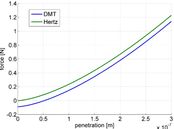
Figure 28 Force-to-penetration law in the DMT model. 45
Figure 29 View of a TM-like surface as measured by a profilometer. 46
Figure 31 From the top left: turbo-molecular pump, ionic pump, ionic and scroll pumps, plasma, 2 views of the interferometer, electronics rack, support system (needles), RTmu and the actuators that allow to change its posi-tion/attitude, support system together with the RTmu, actuators of the pivot of the pendulum with a detailed view. 51
Figure 32 Rendered view of the RT mock-up and the ultrasonic piezo actuator that moves it. 52
Figure 33 View of a TM mock-up (0.0096 kg). The central part is the Au/Pt gold coated in-sert. 52
Figure 34 View of the inside of the TMMF. 53
Figure 35 Contact forces between TMmu, release tip (a’) and blocking needles (b’) in the TMMF. Dotted lines represent force profiles in the in-flight release (Fig. 26) 53
Figure 36 Rendered view of the core of the TMMF, as used in the repeated light TM and high-load test campaigns. 58
Figure 37 Histograms of transferred momentum. 59
Figure 38 Histograms of peak pull-off force. 60
Figure 39 Angular dependence of transferred momen-tum. 60
Figure 40 Angular dependence of the pull-off force. 61
Figure 41 SEM images of the release tip after the measurement campaign showing spots of gold (points 1, 95% top, 89% bottom), whereas its bulk concentration (points 2) is 78% and 80%. 65
Figure 42 Microscope view of the contact areas be-tween the release tip and the TM. Left a native contact. Right the area of contact after two measurement campaigns. The radius of the damaged surface is on the order of that expected from the Hertzian contact ( 35µm). 67
Figure 43 Momentum calculated from Eq. 43 as a function of the measured momentum. 67
Figure 45 Local misalignment angle. This angle is or-thogonal to that of Fig.44 69
Figure 46 Example of TM acceleration as measured and after correction in the high preload test campaign. 71
Figure 47 Model of the system supporting the TM. 72
Figure 48 TM/needles measured and identified mo-tion. 73
Figure 49 Needles push derived from the model. The contact behaviour between TMmu and RTmu is derived by the difference between the push and the measured force. 73
Figure 50 Detail. Needles push derived from the model. The contact behaviour between TMmu and RTmu is derived by the difference between the push and the measured force. 74
Figure 51 Set of forces measured on the TM. The datasets are synchronized with respect to the first peak. 75
Figure 52 Peak force as a function of the test exe-cution order. 76
Figure 53 Force-to-elongation functions (3 out of the 107 available). Both force and elongation signals are filtered with a Blackman with a 3 kHz cut-frequency. 76
Figure 54 Surface profile before the experimental cam-paign. 77
Figure 55 Difference between the surfaces profiles. 78
Figure 56 Section of the surfaces along a line that highlights the differences. 79
Figure 57 Surface coordinates distributions. The num-ber of points is very high (1286575), thus even a small visual difference determines a failure of the hypothesis test. 80
Figure 58 Contact forces between TM, release tip (a’) and blocking needles (b’) in the TMMF. Dotted lines represent force profiles in the in-flight release (Fig. 26) 81
Figure 60 Adhesion force-to-elongation curves esti-mated from 3 best-fits and their covari-ance matrix with uncertainty (±σ). More than 40 are available. 84
Figure 61 Release velocity probability distribution ob-tained from Montecarlo simulations. 87
Figure 62 Release velocity distributions. (a) adhesion effect (b) other effects (mechanism and initial load) 87
Figure 63 a) Simulated release velocity as a function of A1 and λ, b) best fit error. 88 Figure 64 Estimation of the worst case velocity as a
function of the tip radius. The two curves are an upper and bottom estimation of the worst-case. 91
Figure 65 Electrodes surrounding the TM and stan-dard reference system (courtesy of Airbus Defence and Space). 94
Figure 66 Electrical field around the TM, with the Plungers retracted. 95
Figure 67 TM velocity along z with different volt-ages. The 2 V line singularity is the effect of the contact and does not have physical sense. 97
Figure 68 Minimal distance between TM and Plunger estimation. The small picture shows the closest couple of points. 98
Figure 69 Open View of the CubeSat 105
Figure 70 Caging and housing (with a DOSS board). The ruler is in inches. 106
Figure 71 Housing model for shaking test. The hemi-spherical recess on the bottom is here con-nected to a load cell. 110
Figure 72 CAD model of the housing disassembled. 111
Figure 73 Von Mises stress and the deformation (en-hanced) of the housing in caged static sta-tus. 113
difference inside the housing (legend from top to bottom). 116
Figure 77 Example of frame captured by the high speed camera. 122
Figure 78 Trajectory of the RTmu in the very first instants. 122
Figure 79 Rendered view of the core of the experi-ment as improved for mitigation of shear motion. 123
Figure 80 Trajectory of the RTmu in the very first instants. 124
Figure 81 Example of TM acceleration as measured and after correction in the high preload test campaign. 128
Figure 82 TM motion without the linear trend. The distortion of the signal is represented by the saw-tooth behaviour. 129
L I S T O F TA B L E S
Table 1 Applications of Drag-free Technology 3
Table 2 LISA Technology Package Contributions [70] 22
Table 3 TM state requirement 24
Table 4 Example of estimated model parameters 39
Table 5 Key parameters values for the light TM (old campaign) 59
Table 6 Key parameters values for the light TM (2014) 62
Table 7 Key parameters values for the intermedi-ate TM 62
Table 8 Key parameters values for the heavy TM 62
Table 9 Contribution of the effect of the residual preload 63
Table 11 Results of the test campaign with high residual preload. 75
Table 12 Surfaces Standard Deviation and Noise 79
Table 13 Force Contributions 96
Table 14 DFACS: disturbances and actuation, [38] 97
Table 15 Modal analysis results 112
A C R O N Y M S
CMV Caging and Vent Mechanism
DFACS Drag Free and Attitude Control System EH Electrode Housing
GPRM Grabbing, Positioning and Release Mechanism ISS Inertial Sensor Subsystems
LISA Lisa Interferometer Space Antenna RT Release Tip
RTmu Release Tip mock-up TM Test Mass
TMmu Test Mass mock-up
TMMF Transferred Momentum Measurement Facility
1
I N T R O D U C T I O NA purely free-falling object is defined by the absence of all external forces other than gravity. Such a motion is also called geodesic or drag-free, as a reference to the main source of non-gravitational interactions in Low Earth orbits.
In drag-free space missions, a free-floating object, usually called test mass (TM), is enclosed into a satellite. The spacecraft acts as a shield and protects the object from disturbances, due to forces other than gravity. These disturbances are the result of external interac-tions (air drag, solar pressure, Earth magnetic field) and spacecraft-generated effects (gravitational attraction, mechanical, electrical and thermal noise). The core of a drag-free satellite is the Gravitational Reference Sensor (GRS). This device is constituted by a housing and a set of sensors that measures the TM position. The TM trajectory is used as a reference for the orbit through a control system that commands the actuation of the thrusters and counteracts the non-gravitational forces applied on the spacecraft. Unfortunately, as seen later, a small fraction of forces, other than gravity, will always act also on the TM.
The drag-free trajectory is of great interest for both fundamen-tal physics experiments and spacecraft navigation technologies. That is why drag-free missions have been conceived since the early 60s, [80, 61]. However, since DISCOS flight on TRIAD in 1972, [1], only few of them have been actually flown, because of the technical chal-lenges. One of the main critical factors in obtaining drag-free motion is the transient between the launch phase and normal operations. As a matter of facts, in most of these missions the need arises to constrain the TM during launch. Such a constraint has then to be removed leaving the TM in a proper state for operation.
The phase between the constrained and free-floating motion is calledrelease. The importance of this phase has been recognized since the early times of drag-free technology, [51]. A good performance of the release depends on the impulse transferred to the test mass in this phase, which has to be as close to zero as possible. One of the main obstacles in obtaining this result is the adhesion phenomenon that makes difficult the removal of mechanical constraints without applying a force on the test mass.
An example of the criticality of drag-free projects is the LISA-Pathfinder mission, whose launch is planned for the end of September 2015.
The content of this thesis is the summary of activities aimed at assessing the release phase for drag-free missions. Particular emphasis is given to the LISA-Pathfinder case, that constitutes the state of the art, up to now.
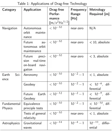
The next sections of the Introduction will highlight the motivation for drag-free technology for both scientific and technological reasons. A first overview of such motivations is given in Tab. 1, presented in [31]. Such a table summarizes all the applications and scientific fields of drag-free technology and provides an estimate of the required level of purity of the gravitational action (i.e. the amount of other interactions) and the frequency range of interest. In some cases the measurement requires the presence of more than a single drag-free object, such that a relative quantity is sensed.
In the last section of this Introduction a summary of the thesis content is finally provided.
1.1 scientific motivation
Space is a privileged environment for fundamental physics experiments [100]. It allows -for instance- long distances, long interaction times, large velocity changes and absence of seismic noise. Among all, the noise free environment with sometime harsh, but stable thermal, elec-tric and magnetic conditions is extremely precious for most experi-ments [35]. It is well known how the human space age began under the push of military needs. Both the first rockets and the moon race were in truth weapons or strongly linked to weapons and to matters of geopolitical power.
Table 1: Applications of Drag-free Technology Category Application Drag-free
Perfor-mance [m/s2Hz1/2]
Frequency Range [Hz] Metrology Required [m] Navigation Autonomous orbit mainte-nance
< 10−10 near-zero N/A
Future au-tonomous orbit maintenance
< 10−10 near-zero < 10, absolute
Future preci-sion real-time on-board navi-gation
< 10−10 near-zero < 3, absolute
Earth Sci-ence
Aeronomy < 10−10 10−2−1 < 1, absolute
Geodesy < 10−10 10−2−1 < 10−6, dif-ferential Future Earth
Geodesy
< 10−12 10−2−1 < 10−9, dif-ferential Fundamental
Physics
Equivalence principle tests
< 10−10 10−2−1 < 10−10, dif-ferential Tests of general
relativity
< 10−10 near-zero < 1, absolute
Astrophysics Gravitational waves
< 10−14 10−4−1 10−11, differ-ential
purposes”1. All this proves the increasing importance of the space environment for science.
Unfortunately, space missions have also peculiar disadvantages: • long time for preparation and development;
• no access to the payload during operation;
• no access to the payload for a post-experiment analysis. At the same time, the complex and long development as well as the search for an ideal 100% reliability have a negative impact on the costs that often become huge.
In the frame of space-based experiments, drag-free technology is proven to be fundamental in a wide range of scientific fields [93]. Examples of them are:
• aeronomy;
• study of the Earth’s geoid; • study of gravity;
• detection and analysis of gravitational waves.
Indeed, these studies have very different essence, from short-term ap-plication to fundamental research. As example, the knowledge of the Earth’s geoid would allow the prediction and study of catastrophic events due to scale change in water distribution and, at the same time, the detection and study of gravitational waves ”has the poten-tial to transform much of physics and astronomy [...] and to reshape the science questions of the future” 2.
Independently from the type of study, drag-free concept promises to open a whole new type of measurements promising for both a better knowledge of our planet and the understanding of the foundations of the universe.
1.2 technological motivation
Drag-free technology is not only a requirement for several physics space missions, but also a path to autonomous orbit control and main-tenance and fuel and operational cost savings [62].
Such a NASA study analyzes the possibilities and the challenges of drag free technology. It highlights that missions whose drag is contin-uously compensated provide the following advantages:
1. a 50% fuel savings for satellites in LEO with altitude smaller than 350 km. The savings are computed with a comparison to a spacecraft whose orbit is corrected once every month; 2. a 30%-50% reduction in navigation error;
3. substantial cost savings for a constellation of satellites in LEO. The 350 km figure depends on the capability of reducing the non gravitational noise generated on the TM by the spacecraft itself. Such a noise must be a negligible fraction of the other interactions. Up to now, this appears to be economically convenient in low orbits where
drag is a substantial effect. On top of the technological advantage, the use of drag-free makes the need of correcting satellite orbits3 less and less important. The operational costs would then be further reduced. It is interesting to link this analysis with one of the main issues in modern space engineering: space debris. Fig. 1 (from [58]) shows that the concentration of debris is limited below 400 km. This hap-pens because atmospheric drag is able to naturally clean space in a reasonable time below that altitude. As a consequence, an increased economic profitability of orbits lower than 350 km would also have benefits for the risks of this missions, with additional savings, and for the cleanliness of space.
Figure 1: Debris concentration as a function of the perigee of their orbit [58].
Lastly, the core of drag-free missions can be either a GRS or an accelerometer. In facts, the structure and functioning of a GRS is very similar to that one of precise accelerometers [63], in which the TM is electrostatically constrained -or suspended- to the spacecraft and the measurement of the actuation needed on it is an estimate of the acceleration. The development of drag-free technology is then also a push for more accurate and precise accelerometers.
1.2.1
Examples of space projects with key drag-free
tech-nologies
As described above, the drag-free concept relies on a spacecraft fol-lowing a TM, with no forces applied on the TM by the control system. The same concept can be inverted such that the TM is kept centered in its housing by the control loop while the spacecraft follows a certain trajectory. In such a case the force applied on the TM is the output, instead of the force applied on the spacecraft. The name of this con-cept is accelerometer mode and has already been implemented on flown space missions.
A few examples of projects relying on the drag-free or accelerometer concept are listed in the following. It is worth noting that the drag free mode can be implemented in slightly different ways (i.e. the force on the TM is not zero, but is only minimized according to a certain criterion) as is well summarized in [48].
triad . Goal: extend the time between ephemeris updates4 to 10 days, [1, 33]. This means the residual acceleration has to be below 10−10ms−2. TRIAD achieved an impressive 5× 10⁻¹¹ms−2.
gravity probe-b, gp-b . Goal: test of two unverified pre-dictions of general relativity: the geodetic effect and frame-dragging. It was a combined effort of NASA and Stanford Uni-versity and it was launched in 2004. The final results were shown in 2011, [41].
satellite test of the equivalence principle, step
. Goal: test of the weak equivalence principle, [78]. This mis-sion is in the preliminary design phase at Stanford, but the funding for a further completion is not secured yet.
grace .Goal: measure Earth’s gravity field anomalies. Gravity Re-covery and Climate Experiment is a mission launched in 2002. It consists of 2 spacecraft in the same polar orbit. GRACE uses microwave ranging and an accelerometer in each satellite in order to accurately measure the relative change in speed and distance of the two spacecraft, [91].
goce . Goal: map the Earth’s geoid with the highest accuracy and precision up to now, [36]. The Gravity Field and Steady-State
Ocean Circulation Explorer main instrument was a highly sen-sitive gradiometer, consisting of an array of accelerometers (three pairs). The mission was launched in 2009, was extremely successful and ended its life in November 2013. The LEO had a 250 km altitude and, in order to minimize drag force, the spacecraft had an aerodynamic shape.
microscope . Goal: test of the weak equivalence principle with an accuracy of one hundred times better than the one obtained with experiments realized on Earth, [94, 54]. Launch planned for 2016.
1.2.2
Pushing new technologies: the hold-down and release
case
Successful drag-free missions require the further development of sev-eral novel technologies, that are already used in space projects, but are not able to guarantee the challenging performance needed for a drag-free satellite. Among them, reliable and long-life micro-N thrusters are indeed critical for an accurate control of the spacecraft orbit. Laser interferometry provides the mean for precise measurement of the TM position, especially if the relative distance between many TM is required. Finally the minimum impulse release of the TM must be guaranteed at the beginning of science or navigation operation, af-ter LEOP5. This need represents well the transition from pyrotechnic to precise separation, that is happening in these days for safety and reliability reasons that go beyond the drag-free scope.
Space mechanisms are very often among the most critical systems in a spacecraft. They are so critical that the European Union lists the Space qualification of low shock Non-Explosive Actuators among the urgent actions in the scope of its Horizon 2020 programme. This fact is of course true also in the drag-free missions case where the hold-down and release of the TM is a single-point of failure for the entire project.
In general, the systems of this kind can be classified in one of the following categories:
• Pyrotechnics: the separation is produced by the firing of an explosive. Such systems are very energy efficient, quick and reliable, thanks to the long experience of use. However, they determine a shock on the spacecraft that may not be
pliant with the payload. At the same time, the use of explo-sives always raises some concerns on the safety and testing on-ground.
• High Energy Paraffin actuators: that are based on the large ex-pansion of paraffin wax from the solid to the liquid state. These systems can generate very high forces and can be repeatedly actuated. However, they are not reliable when a simultaneous action of more devices is needed.
• Burn wire mechanisms: the separate parts of the mechanism are kept together by a wire. The ignition of the release is triggered by the melting of this wire. These devices can be operated in a very quick time (order of magnitude: ms). LISA-Pathfinder release mechanism has some analogies with the paraffin actuator in terms of performance. However, on top of that a very quick time of action is needed as well as a certain control of the position. For this reason the LISA-Pathfinder case represents also a first in the field of hold-down and release devices and a mission critical function [37].
1.2.3
Object Injection in Geodesic Conditions
The need to bring a test mass from the Earth environment to free-fall or suspended conditions requires the development of challenging technologies and deep studies. During launch, the forces applied to the TM are several orders of magnitude higher than during the science phase in space. At the same time, the TM and its housing electronics need to be properly protected from the harsh launch environment.
[16] highlights two different strategies for facing the launch issue: leave the TM free of moving inside the housing or design a caging system. In the first case, the main advantage is the simplicity. On the other hand, the safety of both TM and housing must be verified and guaranteed by careful design of the housing. In the second case, the development of a caging-dedicated system reduces the reliability of the project, but is more applicable in general as it leaves more freedom in the design of the housing. A quantity that suggests which strategy is better in each case is the impact kinetic energy that the TM would have during launch [30]:
Kimpact = 1 2mv
2
impact = 1 2m(
√
where m is the TM mass,a the launcher mean acceleration while the TM moves, d the potential free motion distance (in absence of any caging). Assuming the launcher performance is roughly the same, the main quantity is then the product between mass and free distance. Fig. 2shows the value of mass and free space in a few missions, [16]. The threshold value appears to be about a mass-distance product of 10−4 kg m.
Figure 2: Free mass vs. free-path in several space missions. 1 without caging, 2 without caging, but with gaseous or liquid damp-ing, 3 with caging
during launch, the loads and vibrations of that phase will break any adhesive contact that may have arisen in earlier test, integration or storage phases. A small joining force may be eventually present and an electrostatic system must be designed in order to provide a detaching force. On the other hand, the use of a caging system means that a constant high load is applied onto the TM during launch. Such a load may determine high adhesion. The caging system has to be designed accordingly.
Most of this thesis describes the LISA-Pathfinder example. In this mission, a caging system is needed and electrostatic actuation is very limited, compared to adhesion. The object injection strategy has then to deal with one of the most critical cases.
1.3 thesis structure
The main topic of this thesis is an example of the technical devel-opments pushed by drag-free technology and represents a small step forward in space-mechanism tribology and release devices. The release mechanism conceived for LISA-Pathfinder is a first in space history. As every separation device, it has a dual purpose: secure the payload (or part of it) against the launch loads and cleanly release it once in orbit.
The core of this work follows a system engineering approach, em-phasizing all the different aspects of the release, and is organized in 7 chapters:
1. The second chapter provides an introduction to eLISA, LISA-Pathfinder and the main systems involved in the release. 2. The third chapter describes more in detail the release
mecha-nism, presents an electro-mechanical model and the procedure followed for the identification of the model’s parameters. 3. The forth chapter overviews the adhesion phenomenon and
some basic theory.
4. In the fifth chapter a detailed description of the experimental facility and procedure is provided. Together with this descrip-tion particular care emphasis is given to the presentadescrip-tion and preliminary discussion of the results.
6. The seventh chapter broadly summarizes the working principle and the performance of the systems and procedures involved in the release in a more general sense. That means the systems with an interaction with the TM after the mechanical release. 7. The last part provides information on the preliminary design on the housing for the Test Mass in a Stanford-UFL6 -NASA-KACST7 proposed Drag-Free CubeSat.
6 University of Florida
2
T H E L I S A PAT H F I N D E R S PA C E M I S S I O NThis chapter overviews the eLISA and LISA-Pathfinder goals, main features and critical points as well as an introduction to the TM release issue, which is intimately linked to the success of both missions.
2.1 elisa overview
The evolving Laser Interferometer Space Antenna, eLISA, is an ESA Large class mission conceived to measure gravitational waves. In 2013, the science theme ”The Gravitational Universe” [92] has been selected by ESA for an L3 launch slot, but the history of this mission begins long before this milestone. Among all, it has been the object of several technological and scientific studies, a candidate for combined efforts of both ESA and NASA [32] and for the just-European L1 slot (under the name of New Gravitational Observatory, [12]). Unfortunately, budget constraints have often delayed the project, but this long process is not fully negative as it has allowed decades of intensive technological studies and preparation.
Almost the entirety of the space missions observe the Universe by means of electromagnetic radiation. However, most of the Universe is not visible electromagnetically and must be sensed in a different way. We can listen ([10]) to the Universe by means of gravitational waves that, thanks to their weak interaction with matter, can transport in-formation for very long distances. Unfortunately, this weak interaction is also the reason why the detection of gravitational waves is so chal-lenging.
The goals of eLISA are summarized in the following, [92,97]: 1. observe the merging of massive black holes and study their
mass, spin and redshift. This will allow, for the first time, the exploration of the low-mass part of the black-hole population (104−107Msun).
2. analyze EMRI1 especially those happening in black holes with masses about the mass of the black hole that sits at the center of our galaxy.
1 Extreme Mass Ratio Inspiral, that is a compact start (neutron star...) pulled in a highly relativistic spiral orbit by a massive black hole
3. test General Relativity with un-precedent sensitivity, that could allow measuring even small deviations from Einstein’s theory. 4. observe compact binaries systems. Only a small fraction of the
stars are companion-less, the majority is part of a binary or even multiple system. If the orbit separation is small, these systems evolve into compact systems.
5. provide precious information on the nature of gravity and help the development of a physics theory capable of taking into ac-count both particle and quantum elements and large scale ef-fects. eLISA is a corner element of a larger picture of fundamen-tal physics experiments that already includes high-energy par-ticle accelerators, such as LHC [40], and cosmological probes, [100].
These targets will be reached measuring the waves in the 0.1 mHz -1 Hz range, which is not accessible on Earth due to phenomena such as seismic noise and tides and therefore justifies the need of a space mission.
Figure 3: Left: eLISA constellation. Right: spacecraft concept. [92]
Thanks to the 20-year work on LISA, eLISA mission concept is already well defined. eLISA will be a 3 spacecraft mission shaped as a triangular constellation in heliocentric orbit.
The technical limits on the interferometer are the constraint on the triangle side length. The laser link will sense the relative positions of the free falling test masses, that are affected by gravitational waves.
The last concept provides 4 identical payloads, 2 mounted on the mother and 1 on each daughter. Each of these units consists of a Gra-vitational Reference Sensor (GRS) that hosts a 46 mm Au/Pt cubic TM, a UV discharge system, an electrostatic suspension controller and a caging and release mechanism (see next section for further details). Beside the GRS, each payload hosts a 2 W telescope, for spacecraft-to-spacecraft sensing, and an optical bench for the spacecraft-to-TM position. Indeed, the road towards a gravitational telescope is still long and challenging and the final concept may have differences from this overview.
2.2 lisa pathfinder
Several of the technologies mentioned in the previous section are very critical for the mission success and are also hard to be tested on-ground. An entire space mission has then been conceived in order to facilitate technological development and demonstrate the eLISA con-cept. This mission is called LISA-Pathfinder and it is an ESA/NASA space probe to be launched in September 2015 [15, 5, 6, 97].
The basic idea is to reduce the arm length between a pair of TM from106 km to 35 cm. The two TM are then enclosed and shielded by the same spacecraft. In the main science experiment, one of the TM is drag-free along one linear DoF while the other DoF are controlled by the electrodes. The second TM is electrostatically actuated on all the DoF at low frequencies in order to follow the first TM and assess the residual acceleration. See Fig. 4 for a visual explanation.
The goals of LISA Pathfinder (Fig. 5) are summarized in the fol-lowing points:
1. demonstrate the possibility of reducing the non-gravitational disturbance acceleration below:
∆a 63×10−14
" 1+ f 3mHz 2#
ms−2Hz−1/2 (2)
Figure 4: LISA Pathfinder core, schematic view.
Figure 5: LISA Pathfinder in Thermal Vacuum Chamber, courtesy of Airbus Defence and Space.
It is worth noting that such an approach is conservative as the suspension noise of the non drag-free TM is not present in a full LISA configuration, [8].
2. demonstrate that the laser interferometer is capable of a reso-lution below:
∆x69×10−12
"
1+
f 3mHz
2#
Figure 6: LISA Pathfinder chassis, courtesy of Airbus Defence and Space.
3. assess a large set of critical technologies such as discharging system, micro-newtonian thrusters, drag-free control system and caging and release mechanism.
Beside this objective, LISA-Pathfinder (Fig. 8) will also be a space laboratory for testing the model of several non-gravitational forces in interplanetary space.
Traditional Space Science distinguishes clearly between payload and spacecraft systems, in LISA-Pathfinder this distinction is hardly appli-cable: spacecraft and payload act much more like a unique unit.
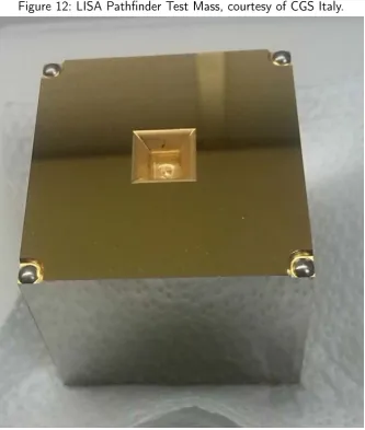
The most important subsystem is the Inertial Sensor Subsystem (ISS), Fig. 9. It includes the electrode housing (in charge of hosting the TM and sense/actuate its position, Fig. 10and11), the front-end electronics, the vacuum system2, charge management (in charge of avoiding the accumulation of charge on the TM, due to cosmic rays and solar particles), the caging and release system and of course the TM (Fig. 12). Each TM is a 1.96 kg 30% Pt-70 % Au 46 mm side cube. It must have a very high density homogeneity (<< 1µm pores) and the center of gravity must be closer than 2µmto the geometrical
Figure 7: Sources of acceleration noise (design requirements), [8].
center. The magnetic properties are also very challenging (magnetic susceptibility: –(2.3±0.2)×10−5).
The sensing of the TM position is performed both with the housing electrodes (part of the ISS) and the interferometer (part of the OMS, see later).
As far as the electrodes are concerned, a trade off has to be found between sensing and actuation authority and the disturbances due to uncontrolled electric fields inside the housing. These fields are due to localized time-varying changes in the charge density on the surface of both electrodes and TM. Indeed, such an effect applies disturbance forces and is particularly critical as every force on the TM reduces the purity of the drag-free motion, which is the main goal of the mission. Both the uncontrolled fields and the authority increase when the TM-to-Housing gap becomes small. A gap of about 4 mm has then been chosen. Indeed, such a choice has consequences also on other devices, as will be shown later.
Finally, the ISS is also in charge of minimizing the TM-to-spacecraft gravitational attraction by means of a set of compensation masses [7] and guarantee proper temperature stability.
Figure 8: LISA Pathfinder chassis, courtesy of Airbus Defence and Space.
the main sensor, for science purposes. Fig.13shows the optical bench during integration.
Finally, in order to maintain the spacecraft in a drag-free orbit compliant with the requirement, a micro-propulsion system is needed. The thrusters initially designed to this purpose were the Field Emis-sion Electric Propulsors (FEEP). However, due to bad performance in terms of lifetime, a cold-gas system was eventually preferred. Such a system has also the advantage of being flight-proven, as it is the same mounted aboard the GAIA spacecraft.
It can be easily shown that all these sub-systems are intimately interlinked. The division is made for management purposes and for allowing the geographical distribution of tasks, as usually performed by ESA.
Figure 9: LISA Pathfinder Inertial Sensor Head. The optical windows for the laser light are substituted by plane flanges, courtesy of CGS Italy.
2.3 caging and releasing of the test mass
Figure 10: LISA Pathfinder Electrode Housing, courtesy of CGS Italy.
the high loads of launch to the extreme conditions of vacuum. At the same time their reliability must be maximized, for obvious reasons.
Mechanism have to be designed such that their performance are compliant with the requirement defined at system and subsystem level. On-ground environment is clearly different from space. The qualifica-tion and validaqualifica-tion before flight are therefore always challenging.
Figure 11: LISA Pathfinder Electrode Housings after thermal-vacuum testing, courtesy of CGS Italy.
Table 2: LISA Technology Package Contributions [70]
Country Responsibility
France Laser Modulator
Germany Co-PI, Interferometer design, LTP architect, Reference laser unit Italy PI, Inertial sensor design, Inertial
sensor subsystem, Test Mass, Elec-trode housing
The Netherlands Inertial sensor check-out equipment Spain Data management unit, Data
diag-nostic system
Switzerland Inertial sensor front-end electronics UK Phasemeter assembly, Optical bench interferometer, charge management system
ESA Coordination, Caging & release mechanism
Figure 12: LISA Pathfinder Test Mass, courtesy of CGS Italy.
LISA-Pathfinder release device sums these criticalities as it has to both separate the TM from the spacecraft with a very limited relative velocity and also to face a tribological phenomenon that has never been studied in real dynamic conditions: adhesion.
Figure 13: LISA Pathfinder optical bench during integration, courtesy of University of Glasgow.
produce serious damages [16]. Second, not only the TM but also any other surrounding device must be either gold-based or gold-coated, in order to limit non-uniformity of surface work function and related uncontrolled stray force. Third, due to the large gaps to the electrodes the actuation authority is very weak (5×10⁻⁷ N), such that after the release the capacitive control system is able to stabilize the TM only if its initial state is limited by very demanding upper bounds as listed in Tab. 3.
Table 3: TM state requirement
State Value
offset along x, y and z ± 200 µm linear velocity along x, y and z ± 5 µm/s angle around x, y and z ± 2 mrad angular rate around x, y and z ± 100 µrad/s
As already experienced in space mechanisms [72, 82, 53, 39], ad-hesive interactions between the TM and a lock/release device are expected, enhanced by many boundary conditions such as vacuum, fretting and inhibition of surface oxydes formation. Moreover, the presence of gold coating on the TM surface and the exclusion of anti-adhesive coatings on any surface exposed to the TM limit any design reduction of adhesion in vacuum. The estimation of the ad-hesive interactions between the TM and a lock/release device makes it possible to rule out any static disengagement of the two bodies performed by the capacitive actuation, as they result orders of mag-nitude larger than the force authority. The most promising strategy is therefore to split the launch lock and in-flight release functions, that require forces of different orders of magnitude.
2.3.1
Caging and Vent Mechanism: CVM
The Caging and Vent Mechanism is in charge of: • hold the TM during launch.
• hand-over the TM to the Grabbing, Positioning and Release Mechanism (GPRM) as a first step of the release.
Such a system has to complain the following design constraints: • survive and sustain launcher vibrations
• no magnetic materials • no liquid lubricants
• low-shock during hand-over ( < 200 g SRS3)
In the resulting design, the TM is held by a set of 8 fingers grasping the 8 TM corners.
Eventually, the CVM (Fig. 14 and 15) consists of two equal and opposed subsystems, which are assembled to firmly constrain the TM with a set of 8 fingers, engaging the cube on its corners with a force of about 300 N each [101,102]. A preloaded toggle mechanism performs a single-shot spiral cam driven retraction of the fingers in order to break the strong adhesive interactions produced at the contacts by the high pressure. The strength of adhesion (on the order of N) and its asymmetry on the 8 contacts makes it possible to exclude that this retraction can release the TM with the requirements listed in Tab. 3. The mechanism chosen is not able to perform multiple strokes.
Figure 14: Caging and Vent Mechanism concept [101].
2.3.2
Grabbing, Positioning and Release Mechanism: GPRM
Figure 16: Views and details of the GPRM, courtesy of RUAG Schweiz AG, RUAG Space and MAGNA International Europe.
The Grabbing, Positioning and Release Mechanism [68, 67, 60,
75] is conceived for completing the CVM action and release the TM with limited contact load (≈ 1 N). In order to meet the expected performance, the GPRM must:
• Grab the TM from all the positions/configurations possible inside the housing.
• Avoid damaging the TM.
• Allow multiple caging and release operations. • Avoid magnetic materials.
Figure 17: Caging Mechanism during thermal test, upper view. The system in the center with blue and red wires is the GPRM, courtesy of CGS Italy.
by means of opposite plungers, which are actuated by a long stroke (on the order of 10 mm) piezo-walk actuator. This actuator gener-ates motion through succession of coordinated clamp/unclamp and expand/contract cycles of a set of smaller piezo stages. Conversely, the release phase is performed by two release tips, which are com-manded by piezo-stack actuators.
The Release Tip (RT) is the system included inside the plunger and is the last device mechanically constraining the TM. After the plunger has engaged the pyramidal recesses, starts the hand-over phase. In this phase the plunger is cyclically retracted of small amounts (≈ µm) while the RT is extracted. This coordinated movement allows a continuous contact between the TM and the GPRM and a load below 0.4 N.
Figure 18: View of the GPRM during alignment tests at Magna.
Summarizing, the release procedure consists of the following phases, Fig. 19:
1. the TM is constrained by the CVM during LEOP4. 2. the CVM hands the TM over to the GPRM.
3. the GPRM plunger engages the TM pyramidal recesses. 4. the plunger is slightly retracted while the RT touches the TM
on the bottom of the recesses with a contact load below 0.4 N. The plunger looses contact with the TM by about 10 µm. 5. the RT is quickly (≈ 40mm/s) retracted leaving the TM
freed of all the mechanical constraints.
2.3.3
Drag-Free and Attitude Control System: DFACS
The Drag Free and Attitude Control System (DFACS, [43]) is in charge of all the spacecraft actuation, that includes the two TMs indeed. It is therefore responsible of controlling TM attitude and position such that each TM is aligned and centered in the housing after the release. The DFACS is also responsible of all the control activities during the science phase.
Figure 19: Extraction and retraction of RT and plunger.
Figure 20: Electrodes surrounding the TM.
with the robust control concept are shown here. More on the DFACS and the actuation of the TM during the science phase is reported in [43, 42]. Besides, useful insight in the drag-free control concept and in the flight-proven GOCE case is given in [26,27].
The mode in which the control system actuates the TM after the RT retraction is called Accelerometer Control Mode and is aimed at:
• providing 3 axis attitude control of the spacecraft. • capture the 2 TM after the GPRM release.
• move the TM to their nominal position and attitude. • compensate the disturbances.
As a consequence, in this phase, the spacecraft is not drag-free and the TM are forced to follow its trajectory.
The actuation is provided by a set of 18 electrodes (Fig. 20) at a roughly 4 mm distance from the TM. Once again this gap is a trade-off between the actuation authority and the disturbance rejection. 12 of these electrodes are dedicated to actuation. The other 6 provide a voltage bias and for sensing. The frequency of the bias voltage is much higher than the actuation. A detailed model of the electrostatic actuation is described in [23, 38,24].
In general the force between two bodies with a voltage difference is expressed as:
Fel = 1 2
∂C ∂q∆V
where C is the capacitance and q is the axis (that is, if the force along x is desired, the partial derivative is computed with respect to x). The formula for the torques is equal. This same equation can be generalized to several bodies. The force along a certain axis q of a body is then:
Fel,N = N X
j=1 N X
i=1 1 2 ∂Ci,j ∂q ∆V 2 i,j (5)
Eq. 4 makes it possible to easily understand the weakness of the authority. Assuming a planar capacitor of area 5 cm2, gap 3 mm and excitation voltage about 50 V the force between the 2 plates is ≈ 0.5 µNbecause of the vacuum permittivity (8.854×10⁻¹²) at the numerator.
2.3.3.1
The Sliding Mode Control
The sliding mode controller is a non-linear control algorithm. Sliding mode approach guarantees robust control and, with respect to a clas-sical PID it provides a reduced TM overshoot, a fast convergence and a better steady-state accuracy [73]. Besides, sliding mode control al-lows a more general design while PID has to be specified for a single case (the worst one).
The following paragraphs provide a qualitative introduction to the topic, in order to put a frame around the mechanical release. For the details on this algorithm, the reader can refer to [86].
Let’s consider the system:
x(n) =f(x) +b(x)u (6)
where x = [x,x, . . . , x˙ n−1]T and b(x) is bounded bmin < b(x) <
bmax.
Now, ifex is the tracking error, the function s is then defined:
s(ex, t) =
λ+ d dt
n−1
(7)
This becomes a sliding function once:
s(ex, t) =0 (8)
A Lyapunov function can be defined as:
V = 1 2s
2
Figure 21: Sliding mode control applied to a free 2 kg mass.
whose derivative is:
V = d dt
1 2s
26
∀s 6=0 (10)
which means that the system trajectories point towards s=0.
In the case of a free floating mass the sliding surface is:
s =λx1+x2 (11)
where x1 is the position and x2 the velocity.
The derivation of the control law in the DFACS is described in [38]. The basic idea is to constrain the TM trajectory on s = 0 with a discontinuous control such as:
udisc(s) = −ksign(s) (12)
Once ons=0, the system evolution will be something like Fig.21, where one can easily distinguish the reaching phase and the sliding one. Of course the actual system acts in a more complex way and in several degrees of freedom simultaneously.
What is of interest, in the scope of this thesis, is that the TM motion will have an overshoot, that depends on the initial position and velocity, the actuation authority is non-linear and becomes weaker when the TM is far from the housing center and an unknown distur-bance continuously acts on the TM in this phase. On top of the weak average authority of a single electrode at the mm range, there are several other aspects that limit the state the TM can have right after the mechanical release.
1. t = 0+: RT retraction;
2. 0 < t < 15 s: the Plungers move from the initial distance (equal to the Tip length, 15 µm) to 500 µm;
3. t = 15 s: start of observation and control;
4. 15 s < t < 25 s: the Plungers remain at their position; 5. t = 25 s: first estimation of the TM velocity with a less than
5 % error;
6. t > 25 s: if the velocities are assumed controllable the Plungers move in a safe position and the control keeps guiding the TM. Indeed, the observation of the TM velocity is not instantaneous. This adds extra challenges that, together with what has been described before, determine the requirement of Tab. 3.
3
R E L E A S E M E C H A N I S M : M O D E L A N DI D E N T I F I C AT I O N
Piezo-electric devices are widely used for precise positioning both in on-ground and space applications [71, 9]. Several mathematical mod-els are available in the literature to describe their dynamical behaviour. The focus here is on linear models [55], in which relevant quantities like elastic, piezoelectric and dielectric coefficients are considered con-stant. [50] proposes a modelization for control purposes. Similarly to what is proposed in [2], the piezo stack electro-mechanical dynam-ics is here described by means of a lumped element model. Such a model is introduced in [18], where the transfer function from com-manded voltage to RT position is estimated by fitting the predicted dynamic behaviour of the mechanism to the measured one. In the following step, the physical constants defining the system dynamics (which are implicit in the transfer function coefficients) are found and the validated mathematical model is used to simulate the overall re-lease phase by adding the TM dynamics and the effect of adhesion [21]. This last reference represents the first step of the simulation and prediction activity that sees here a substantial advance.
The GPRM release actuator is constituted by a 3×3×18 mm piezo-stack commanding the small release tip, which has a spherical edge with 10 mm radius of curvature. The stack actuator is preloaded by a set of washer springs, as depicted in Fig.23and is commanded by a voltage applied to its ends. The voltage is increased during the pass-over phase from 0 V up to 120 V, at which the tip is fully extracted, and is short-circuited to 0 V through a resistor at the release, [74]. Nominally, the voltage drops from 120 V to 0 V with an inverse-step function. In order to perform the release, the tip is extended and retracted, after few seconds, and no repetition of this action is foreseen. In the absence of a cyclic actuation, it is assumed sufficient to introduce a linear viscous element (labeled b in Fig. 24) to model the overall dissipation of the system. The GPRM release mechanism electro-mechanical model is based on the lumped element scheme of Fig. 24.
Fc is the contact force between RT and TM and can be either compressive, when the tip is initially holding the mass, or tractive, when the tip is retracted from the adhesive contact. A compressiveFc
Figure 23: Cut view of the GPRM plunger with the TM pyramidal recess.
Figure 24: Lumped-element diagram of the GPRM release mecha-nism.
and of the TM, the bonds are elongated. As a consequence, back-action of adhesion is considered because in principle it may limit the quickness of the retraction of the RT and affect the impulse developed. The equations describing the piezo electro-mechanical dynamics are the following:
R Caq˙(t) +q(t) −TemxT(t) =CaE(t) (13)
Mg¨l(t) +Kgl˙(t) −b x˙T(t) −l˙(t)
−
k+T 2 em Ca
(xT(t) −l(t)) + Tem
Ca
q(t) =0 (14)
m¨xRT(t) +b
˙
xRT(t) −l˙(t)
+
k+ T 2 em Ca
(xRT(t) −l(t)) − Tem
Ca
q(t) +Fc =0 (15)
where q(t) is the charge accumulated on the piezo, xRT(t) is the release tip position,R is the resistance of the electrical circuit,Cathe capacitance of the piezo-stack,Tem the electromechanical transducer (or the piezo effect), m the mass of the release tip and half piezo-stack,kthe combined stiffness of the preloading washer spring and of the piezo , b the combined damping, Fc the contact force acting on the mechanism (that is 0 during identification) and E(t) the voltage input.
Differently from [18,21], the mass discretization here adopted con-siders the whole plunger (Mg) constrained to ground by a load cell (stiffness Kg) and the RT attached to the plunger by the preloaded piezo. Similarly to [21], the physical parameters are estimated by means of dedicated tests performed on the mechanism, where the RT is retracted from the extended configuration in the absence of contact forces. The theoretical motion profile of the RT is fit to the measured motion profiles of the mechanism Flight Model (FM) [69], and a covariance matrix is associated to each set of best fit parameters to describe their uncertainty.
The uncertainty is expressed in terms of a covariance matrix. Such a matrix is associated to a best-fit set of parameters with the formula:
where J is a Jacobian matrix, defined as:
Ji,j = ∂xi ∂pj
(17)
withxi the retraction at theithtime sample andpjthejthparameter of the model. The matrixΣis a diagonal matrix, built with the square of the residuals for each sample.
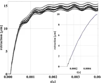
The measurement on 8 different mechanisms are available. They correspond to the 4 GPRM FM equipped with 2 piezo-stacks each (main and redundant). Since the in-flight release will be performed by a pair of such mechanisms, the parameter space can be restricted to the estimated physical quantities, still considering their uncertainty. Fig. 25 shows the measured retractions and in the sub-frame an ex-ample of best fit, whose parameters are reported in Tab. 4. The data are measured by a SIOS SPS 2000 vibrometer at 1 MHz sampling frequency.
If two mechanisms must be commanded synchronously, the need arises to estimate additional asymmetry of the retraction profiles pro-duced by different voltage commands at the output channels of the control unit.
Table 4: Example of estimated model parameters
Name Best Fit Units
R 371.2 Ω
m 9×10⁻⁴ kg Ca 2.3×10⁻⁷ F
k 4.91×10⁷ N/m Kg 2.15×10⁶ N/m
b 9.77 N s/m
Mg 0.019 kg
Tem 5.73 C/m
The actual voltage time profile E(t) commanded by the two chan-nels of the FM control unit has been measured and differs from the nominal inverse-step assumed in [18,21,19]. A drop time on the order of microseconds is required to null the voltage and a limited repeata-bility characterizes the voltage time profile. For this reason E(t) is expressed as:
E(t) =
120−em t :t < 120/em
0 :t>120/em (18)
whereemis the slope of the dropping voltage. The set of measured profiles is limited, therefore the uncertainty onem, whose distribution is assumed normal, is large. The mean value is estimated in 5×10⁷ V/s with a standard deviation equal to 1.02×10⁷ V/s.
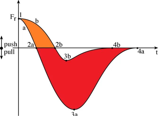
The mathematical model of the release mechanism makes it possi-ble to predict asymmetrical retractions of the RTs, in the limit of the uncertainty of the relevant parameters estimated. The asymmetry of retraction of the two tips is critical because it can affect both the mo-mentum transferred by pushing contact forces between RT and TM (i.e. without adhesion, light gray area in Fig.26) and that transferred by adhesion at the two contacts (dark gray area in Fig. 26). This means that:
Figure 26: Contact forces between TM and release tip during the re-lease phase. The tip a is assumed to be quicker and its adhesion with the TM stronger. The sum of the 2 areas is the momentum transferred to the TM.
• even with equal adhesion strength and elongation at the two contacts, asymmetry of retraction can convert symmetric ad-hesion into momentum.
4
A D H E S I O N B E T W E E N M E TA L S : A Q U I C KO V E R V I E W
Adhesion or cold-welding is a phenomenon that takes places between two metallic objects in contact. As a consequence the two objects remain attached even if a certain external force pulls them apart.
Adhesion is a recognized issue in space applications [72, 85, 82]. It can be high enough to hinder the deployment of even large sys-tems. A famous example is the high gain antenna in Galileo, that was only partially opened during operation around Jupiter. This antenna was shaped as an umbrella. Despite several attempts and different strategies, a few of the antenna ribs did not pop out of the holding cup during the deployment [82,76]. Galileo had to rely its success on a secondary antenna, with a much lower gain, making the result of the whole mission much harder than planned. This example highlights once again the criticality of adhesion and the need of proper studies and tests for each case.
In most applications, adhesion can be limited by a wise material or coating choice, by proper cleaning and lubrication and by minimizing the contact areas. But indeed, all this features have to be a trade off between several opposed needs.
Due to its poor repeatability, adhesion between the rough metallic surfaces of the RT and the TM is expected to be a relevant source of net force on the TM during the release. Unfortunately, in such a case, material, coating and lubrication design choices are constrained by the need of minimizing the non-gravitational force acting on the TM. Only the area of contact has been kept limited in light of adhesion and results in the design of a set of actuators, with gradual reduced area, operated in sequence (CVM, GPRM, RT).
In the following, a basic overview of the standard theories on adhe-sion is given . Although the real behaviour is different because of the use of real engineering surfaces, these theories can provide an initial understanding of the phenomenon, its main parameters and the main references. After this short overview, a detailed description of the ex-perimental facility is provided. Such a facility was designed specifically for part of the qualification of the LISA-Pathfinder mechanism. The main results are also summarized.
![Figure 1: Debris concentration as a function of the perigee of theirorbit [58].](https://thumb-us.123doks.com/thumbv2/123dok_us/539496.2053478/27.595.98.430.261.498/figure-debris-concentration-function-perigee-theirorbit.webp)
![Fig. 2 shows the value of mass and free space in a few missions, [16].](https://thumb-us.123doks.com/thumbv2/123dok_us/539496.2053478/31.595.113.392.220.559/fig-shows-value-mass-free-space-missions.webp)