International Doctorate School in Information and Communication Technologies
DIT - University of Trento
Modeling and Compostion of
Environment-as-a-Service
Tao Peng
Advisor:
Prof. Marco Ronchetti
Universit`a degli Studi di Trento
I owe my greatest debt of gratitude to my advisor, Prof. Marco Ronchetti, who has constantly given me guidance and help. He has provided me invaluable advices on defining the research topic, developing the solution, and formalizing manuscripts. His dedication and enthusiasm to scientific research has encouraged me. He also cares about my student life besides doing research, which makes me feel backed up.
I would like to thank Centro Ricerche GPI for financially supporting my Ph.D. study and giving me the opportunity to experience the real health-care IT system development. Our “capo” (head) Giampaolo Armellin has created an environment for us to focus on research related activities. Anna-maria Chiasera gave me great advices on research and manuscript writing. I often miss the days working on interesting projects with great colleagues: Cristina, Dario, Jovan, Tefo, Manuella, Cesare...
I am grateful to Prof. Fabio Casati for advising me since my master study, and for bringing in the connections to academy and industry outside. Florian Daniel gave me great advices on doing research and formalizing manuscripts, with the expertise on web engineering and business process management and experiences of serving as scientific editorial committees. The senior Ph.D. students also helped me a lot through discussions.
decentralized architecture, and other colleagues.
Wireless-enabled electronic devices are becoming cheaper, more powerful
and thus more popular. They include sensors, actuators, smartphones,
tablets, wearable devices, and other complex devices. They can carry out
complex tasks, cooperating with their “neighbors”. However, it is difficult
to develop mobile applications to exploit the full power of available resources
because the computational capabilities on devices are not homogeneous, and
their connectivity changes with physical movement. We propose a mobile
environment model to describe the connected devices and study the
struc-tural and behavioral characteristics of the environments. Based on the
model, we design the routing protocols and a language to support the
com-position of environments. We propose a framework to provide a unified,
flexible and scalable service for task/process deployment and execution on
top of the heterogeneous and dynamic mobile environments. We compare
different architectures, and discuss the optimization of resources discovery
and routing algorithm. A proof-of-concept framework is implemented and
shows the feasibility of our Environment-as-a-Service approach. Finally,
we explore the theoretical principles and practical techniques for
perfor-mance optimization, including a data prefetching technique and a dynamic
process/task allocation algorithm.
Keywords
1 Introduction 1
1.1 Scenarios . . . 2
1.2 State of the Art . . . 5
1.3 Our Approach: Environment-as-a-Service . . . 7
1.4 Contributions . . . 9
1.5 Structure of the Thesis . . . 9
2 Modeling Environment-as-a-Service 11 2.1 Modeling an Environment . . . 12
2.1.1 Capability . . . 14
2.1.2 Computational Capacity . . . 14
2.1.3 Connection Topology . . . 15
2.1.4 Atomic Environment as a Service . . . 16
2.2 Composition of Environments . . . 16
2.2.1 Aggregation of Computational Capacities and Capa-bilities . . . 17
2.2.2 Three Types of Environment Composition . . . 18
2.2.3 Routing in Composite Environment . . . 19
2.3 Environment Description Language . . . 33
2.4 Implementation . . . 34
3.1 Three Architectures . . . 38
3.2 Centralized Architecture . . . 41
3.2.1 Resources Management . . . 41
3.2.2 Routing . . . 42
3.3 Peer-to-Peer Architecture . . . 42
3.3.1 Resources Management . . . 43
3.3.2 Routing . . . 43
3.4 Hybrid Architecture . . . 44
3.5 Comparison . . . 44
3.6 Justification of Adopting Hybrid Architecture . . . 46
4 Deploying Processes and Tasks onto Mobile Devices 49 4.1 Scenario . . . 51
4.2 Mobile Process Management Approach . . . 55
4.2.1 Services Preparation . . . 55
4.2.2 Process Design . . . 58
4.2.3 Activity Assignment . . . 59
4.2.4 Activity Execution on Mobile Devices . . . 61
4.3 An Extension of BPMN . . . 62
4.3.1 Context constraints for activity assignment and ex-ecution . . . 62
4.3.2 Services provided on mobile devices . . . 63
4.3.3 Example usage of extension . . . 64
4.4 Mobile Process Engine and UI Framework . . . 65
4.4.1 Mobile Process Engine . . . 66
4.4.2 UI Framework . . . 68
4.4.3 Controller of Atomic Environment . . . 68
5.1 Constraint Satisfaction . . . 71
5.1.1 Optional Requirement . . . 72
5.1.2 Satisfaction Factor . . . 73
5.2 Approximate Allocation vs. Optimal Allocation . . . 75
5.3 Algorithm Complexity . . . 76
5.4 Optimization Technique: Data Prefetching . . . 76
5.4.1 Scenario and Challenges . . . 79
5.4.2 Model of Data and Operations . . . 81
5.4.3 Markov Chain based Prefetching Algorithm . . . . 83
5.4.4 Dependency Graph based Prefetching Algorithm . . 88
5.4.5 Simulation . . . 93
5.4.6 Work Related with Data Prefetching . . . 95
5.4.7 Conclusion on Data Prefetching . . . 98
5.5 Task Allocation in Resource-limited Environments . . . 99
5.5.1 Task Allocation Optimization for Resource-limited Environments . . . 100
5.5.2 Task Allocation Optimization for Dynamically In-coming Tasks . . . 103
5.5.3 Conclusion on Task Allocation Optimization . . . . 104
6 Related work 105 6.1 Model . . . 105
6.1.1 Service on Devices . . . 106
6.1.2 Service Discovery . . . 108
6.1.3 Service Composition in Pervasive Environment . . . 109
6.1.4 Distributed Application Processing on Mobile Devices 109 6.2 Architecture . . . 110
7.1 Conclusion . . . 113 7.2 Limitations . . . 115 7.3 Future Work . . . 116
Bibliography 117
2.1 Examples of Routing Tables . . . 20 2.2 Type of Routing Records . . . 25
2.1 An Environment composed by Three Atomic Environments 14
2.2 A more complex composition of Environments . . . 21
2.3 The top level Composite Environment . . . 21
2.4 Tree of Environments . . . 23
2.5 Algorithm: Discover a satisfying Environment . . . 24
2.6 Algorithm: Find the next hop to route a message . . . 26
2.7 Initialization an Environment with no Controller . . . 28
2.8 Join an Environment with Controller . . . 29
2.9 Console of a controller . . . 34
2.10 Barcode task received . . . 34
2.11 Console of a child . . . 34
2.12 SMS task received . . . 34
3.1 Centralized Architecture. All devices form an Environment. A controller (thick circle) manages resources and routings of all devices. . . 41
3.2 Hierarchical P2P Architecture. No controller. Children of an Environment manage resources and routing together. Children can connect to outside and expose aggregated in-formation. . . 41
4.2 Process Design Phase . . . 58
4.3 Activity Assignment . . . 60
4.4 Activity Execution on Mobile Device . . . 61
4.5 Mobile Process Engine . . . 66
4.6 Subset of classes in Mobile Process Engine . . . 67
4.7 Measure blood pressure . . . 68
4.8 Give medicine . . . 68
4.9 Send response . . . 68
5.1 Algorithm: calculate the Satisfaction Factor . . . 74
5.2 Operation Dependency Graph. A vertex represents an op-eration oi, with specified priority oi.priority labeled in the circle. An arrow represents a transition, with probability oi.probability calculated by the framework labeled on the arrow. The number below the vertex is the value of opera-tion oi.value. . . 84
5.3 Incremental Prefetching (step 1) (The number below the vertex is the value of operation): B and C are one hop reachable and B has the highest value, so the prefetch B; then C and D are one hop reachable and D has the highest value, so prefetch D; prefetch the last one - C. . . 87
arrows - dependencies; probabilities under vertices - initial
/ accumulated / normalized. . . 90 5.6 Priority Passing in DG. Number in vertices - priority / max
dependent priority; number under vertices - probability /
Introduction
With the development of electronic and telecommunication technologies, devices are becoming smart and inter-connected. These connected devices (including sensors, actuators, smartphones, tablets, domestic electronics, smart vehicles, and other complex devices) are playing more and more im-portant roles in our daily lives and industrial environment. According to CISCO [19], 8.7 billion objects were connected by 2012, and the number is expected to reach 50 billion by 2020. These devices provide very diverse capabilities and connect with each other via wired or wireless connections (Wi-Fi, Bluetooth, etc.). They assist us to monitor and interact with the environment, and carry out complex tasks. For example, devices such as smartphones are emerging as working equipments for workers in different industries [43]. Although each device provides a limited set of capabil-ities, integrated together, they have high potential in different domains, including healthcare, industry automation, emergency response, and many others.
1.1
Scenarios
Healthcare applications, application integration on smartphones and location-aware services are some example scenarios facing this challenge.
Mobile devices are more and more used to provide sophisticated per-sonal healthcare assistance, such as in [61]. A simpler example scenario is: a patient can have monitoring devices such as blood pressure meter, and a clinic has more devices and access to remote repository of healthcare records of patients. To develop an application that assists the blood pres-sure monitoring, the developers need to analyze the available devices and accessible Application Programming Interfaces (APIs) in different environ-ments, connect these resources, and integrate them to provide assistance to the monitoring. When the availability of devices in environment changes or we need to provide new healthcare services, developers need to go over the process again, because the application logic is tightly-coupled with the available hardware devices and other resources such as API access. The emergence of wearable devices those monitor the health status, including watches, chest belts, brings new possibilities for healthcare applications. The need of an efficient way to manage the diverse resources especially on mobile devices is also emerging.
appli-cation integration. Android provides a mechanism for the intra-appliappli-cation invocation, using Intent 1. However, it is merely an interface to invoke ap-plications on the same device, and is not capable for the across-device invocation and sophisticated resource management.
The prevailing of smartphones has created lots of opportunities for the location-aware services. One usage scenario for location-aware services is to apply the detected context information to help users to find the infor-mation of interest under the current situation. According to McKinsey, the number of horizontal Web searches from personal computers in France is outstripped by vertical and mobile searches [46]. People often search on mobile device for facilities (restaurants, hotels, parking places, shops, etc.) nearby current location, or near destination or en route [89]. Different with search on desktop, searching on a smartphone does not only implies a loca-tion to filter the search results, but also implies the urgent need of services at that time and that location, which has a high conversion rate into con-crete business. However, current services on smartphone merely use the detected location information to filter the search results. The matching of users need and the services provided nearby still need to be done manually by the user: he/she has to check the rating of the hotels/restaurants on a website, and open another website to start booking. There are services of integration by mashing up information from correlated websites [98]. For example, the website first shows hotel ratings to user, then allows the user to book the room, and finally suggests car renting service in that city. Mobile context information (including the time, location, user preference, previous services, etc.) can be used as input to provide more accurate infor-mation for the successive service. In some situation where the connection is unreliable, it can increase the service availability to predict the functions that might be invoked and prefetch the correlated data onto mobile device
[63]. It is more attractive if we have a framework that understands both the requirements of the user and the resources availability provided by the facilities, and the framework matches the requirements with resources and starting a user-specific process to take care of the potential needs of the user.
However, it is not easy to create such a framework. We need to cope with the challenges caused by the capability difference and connectivity vulnerability intrinsic to mobile devices and more specifically:
• The capabilities of devices are diverse. Devices are designed to per-form different tasks by interacting with the inper-formation systems and the physical environment. These devices with different capabilities are scattered in the environment, constituting powerful but diverse environments. It is difficult to develop applications and connect these devices to exploit their capabilities.
• The connection across devices are unreliable and costly. Wireless con-nection is unreliable due to the possible obstacle, interference and device movement. And wireless connection is expensive in terms of battery and sometimes also in terms of money.
• The connection topology of devices is complex and changeable. The physical location of mobile devices are changing, thus the connectivity on mobile devices are also changing. The changing topology makes it difficult for application to route a task to the proper destination.
To solve these problems, we first need to answer these questions:
• How can we model the capacity to carry out computation and the
capability to provide services?
leaving of devices?
• How can we provide an abstract description of environmental resources
and the tasks’ requirements, to ease the deployment of tasks in the environment?
All these challenges are difficult with mobile devices in the environments.
1.2
State of the Art
With the advance of network technologies and the emergence of network connected devices, developing software across heterogeneous devices has been a challenge for researchers. In this section, we introduce the state of the art of researches from relevant topics, including Service-Oriented Ar-chitecture, Cloud Computing, Business Process Management and Wireless Sensor Networks. Detailed comparison between existing work and ours will be given later in Chapter 6.
Under the topic of Service-Oriented Architecture (SOA) [28, 76], a set of concepts and tools are developed. Standards and protocols are proposed to bridge the gap between the device interfaces and the business applications [16]. Legacy softwares together with the underlying hardware resources are bundled as autonomous services [76]. Services are invocable using an inter-face description language (e.g., Web Service Definition Language (WSDL) [17]). Implementations are hidden behind the interfaces. And services can compose with each other to provide more complex functions. Web service (WS) defines a Web-based communication interface to implement SOA [4]. Researchers extend Service-Oriented Architecture to involve mobile devices, either to consume or to provision the services [87, 37, 75].
provided, Infrastructure-as-a-Service (IaaS), Platform-as-a-Service (PaaS), and Software-as-a-Service (SaaS) are some of the popular concepts in cloud computing industry [8, 71, 92]. There are also similar concepts such as “grid computing” [33], “utility computing” [72]. The idea behind these concepts is to provide computing resources as a on-demand, elastic and scalable util-ity. Michael Armbrust stated in [8]: “This elasticity of resources, without paying a premium for large scale, is unprecedented in the history of IT.” According to [25], “The term mobile cloud computing was introduced not long after the concept of cloud computing.” Mobile cloud computing refers to the architecture that mobile devices offload resource-intensive comput-ing tasks to the cloud infrastructures. There are researches that integrate the resources available on mobile devices to provide various cloud services, including image processing, natural language processing, crowd computing, GPS/internal data sharing, sensor data application, multimedia search, so-cial networking [30, 18, 81, 100, 52, 13].
However, existing researches fail to address some major concerns on mobile devices. They seldom base on the heterogeneous resources on mobile devices, but assume that mobile devices provide homogeneous functions, such as computation, data store, or certain type of sensing. The diverse capabilities of mobile devices are difficult to exploit.
1.3
Our Approach: Environment-as-a-Service
We propose a model of environment which allows the composition of en-vironments and the task execution in composed enen-vironments. We name the model “Environment-as-a-Service”, which is inspired by the concepts (Infrastructure-as-a-Service, Platform-as-a-Service, Software-as-a-Service) from cloud computing.
An Environment contains a collection of connected devices. It is mod-eled as a service, which implies:
• An Environment is autonomous. An Environment has the necessary
resources to carry out the functions that it provides. Resources man-agement and message exchange are performed within the Environ-ment, but do not depend on external resources.
• An Environment provides a service: it can execute a set of functions in the form of task execution via predefined interfaces. Powered by the composing devices, an Environment can receive computational tasks either from outside of the Environment or from an internal node, and execute the tasks. The service offered by an Environment is ready-to-use functions, so users do not need to worry about device utiliza-tion, resource management, internal messaging, and other contained services. Internal nodes or external users can utilize the published functions on-demand, by assigning tasks to the Environment.
compos-able and decomposcompos-able, Environments are compos-able to scale up or shrink down. The service provided is thus elastic and scalable.
An Environment is modeled as a graph: a vertex represents a device, and an edge represents the capability of connecting two devices. An En-vironment exposes an interface to outside, allowing the deployment and execution of tasks/processes. It manages its internal resources, includ-ing hardware devices and software APIs. Environments can compose into larger Environment, while each composite Environment manages the re-sources and routing on its level. By introducing such composite Environ-ment model, we are able to model the complex environEnviron-ment with hetero-geneous devices, and provide a solution for the resources management and task routing across devices.
To implement the environment model, we explore different possible ar-chitectures and compare the their strength and weakness dealing with dif-ferent devices and tasks. These architectures include centralized architec-ture, Peer-to-Peer architecture and hybrid architecture. Their differences are discussed in detail in Chapter 3.
We adopt the hybrid architecture in our proof-of-concept framework, because hybrid architecture fits better with this type of environment. De-vices deployed in vicinity are more likely to interact with each other on tasks, and they occasionally need to communicate with devices far way.
Based on the hybrid architecture, we design a protocol for service dis-covery and task routing across environments, and a language to describe the environments and the requirements of tasks. The hierarchical compos-ite environments allow devices to join or leave the environments without manual efforts to reconfigure or redeploy the applications, and provides a unified, elastic and scalable service on top of the heterogeneous and unre-liable devices.
solution. We study further optimization considering the resources alloca-tion efficiency, routing performance and robustness to mobile network or device failure.
1.4
Contributions
Our contributions include:
• The model of Environment-as-a-Service, which provides a theoretical foundation to manage the resources (especially on mobile devices) and route the tasks/processes across connected devices.
• The study of architectures to support the Environment-as-a-Service
model. We explored the three possible architectures and adopted the hybrid architecture for proof-of-concept framework.
• An implementation of proof-of-concept framework on Android
plat-form. The framework includes a language to describe the available resources on devices and the requirement of task/process, an algo-rithm to manage the resources and routing, and the implementation on Android platform.
• The approach to optimize the resources discovery and task routing.
1.5
Structure of the Thesis
Modeling Environment-as-a-Service
As we mentioned, mobile devices provide various capabilities to support applications in different industries. To better utilize the capabilities on mobile devices and reuse the domain knowledges encompassed in software modules, one way is to decouple the implementation of software modules and the high level business logic design on top of the available software modules. Existing software architectures such as Service-Oriented Archi-tecture (SOA) [28], focus more on stationary devices, assuming the con-nectivity and availability of resources are stable. We need a more flexible model to describe the resources on mobile devices and unreliable wireless connectivities.
We propose the model of Environment-as-a-Service with the following principles:
1. Hierarchical. In the complex industrial environments, organizations of different level manage different scope of resources. The model should allow different granularity of resources management.
2. Autonomous. In the model, a Environment manages the internal re-sources and provides essential services without depending on external resources.
ments should be able to compose with each other into large Environ-ment and together provide different services.
2.1
Modeling an Environment
Definition 1 (Device) A device (denoted by D) is an electronic equip-ment that can perform certain task(s) and is able to communicate with
other equipment. D denotes the set of all known devices.
Devices include a spectrum of wired and wireless-connected electronic equipment, from sensors, actuators, to smartphones, personal computers, and other complex electronic equipments.
Definition 2 (Capability) A capability of a device is a function that it provides. We assume that all devices share the same taxonomy of
capa-bility description. Each device has a set of capabilities, and we model the
capabilities of a device as an attribute, denoted by Cap(D). The set of all capabilities is denoted as CAP.
For example, for a printer D1: Cap(Di) = 0print0, and for a barcode
reader D2 with a LCD: Cap(D2) =0readBarcode0,0display0.
Each device has at least one connection method, which allows it to connect to other devices those have the same connection method.
Definition 3 (Connectivity) We denote the set of all connection meth-ods between devices as CON. Each device is able to communicate with
other devices over a set of connection methods: Con(Di) ⊆ CON. We
assume that the connection between devices is bi-directional: if a device Di
can directly start the communication and send information to device Dj,
Dj can also directly start the communication and send information to Di.
We indicate this relation as: Di ↔ Dj. Obviously, they need to have one
common connection method: Di ↔Dj ⇒Con(Di)
T
A group of devices can form an Environment, if and only if any two devices can reach each other without passing any device that does not belong to the same Environment:
A group of devices can form an Environment ⇔
∀Di, Dj ∈ Env,∃Dx1, Dx2, ...Dxm ∈ Env, s.t.Di ↔ Dx1∧
Dx1 ↔ Dx2 ∧. . .∧Dx(m−1) ↔ Dxm ∧Dxm ↔Dj (2.1)
Definition 4 (Environment) An Environment comprises a group of el-ements, which can be devices or other Environments, and the connections
among the elements. A tuple represents an Environment Env = (V, E, C): a vertex Vi (∈ V) represents a device or a nested Environment which is
an element of Env, and an edge (Vi, Vj) ∈ E represents the two devices
or environments that are connected (Vi ↔ Vj); for a Vc ∈ C ⊆ V, Vc is
the vertex (device or Environment) that serves as a controller in Env. We denote the set of all Environments as E.
Definition 5 (Device joins an Environment) D ∈ Env represents that a device D joins an Environment Env(V, E, C). As defined in Equation
(2.2), when a devices D joins an Environment Env, it means that either (directly) it is vertex of the Environment Env, or (recursively) it joins an Environment Env0 which is a vertex of the Environment Env:
D ∈ Env(V, E, C) ⇔ D ∈ V or
∃Env0(V0, E0, C0), s.t., D ∈ V0 and Env0 ∈ V. (2.2)
Definition 6 (Atomic/Composite Environment) If the vertices of an Environment are all devices, the Environment is an “Atomic
Environ-ment”. More formally:
1 2
3 10
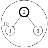
Figure 2.1: An Environment composed by Three Atomic Environments
If one or more vertices of an Environment are Environments, the
Environ-ment is said to be a “Composite EnvironEnviron-ment”. More formally:
Env(V, E, C) is composite ⇔ ∃Vi ∈ V, Vi ∈ E
Since Atomic Environments are the finest elements that we consider, we restrict Atomic Environments to have simple topology: there is exact one controller, and it connects other devices in the Environment. A Composite Environment can have one or more controllers. In Fig. 2.1, E1, E2 and
E3 are Atomic Environments, while E10 is Composite Environment.
2.1.1 Capability
The capability of an Environment is the union of capabilities of all its devices.
Cap(Env(V, E)) = [
Vi∈V
Cap(Vi)
The controller serves as a registry of all the capabilities of the devices in the Environment. Given a request of a certain capability, the controller is able to decide whether there are some devices in the Environment have this capability and how to connect those devices.
2.1.2 Computational Capacity
as computational capacities.
Definition 7 (Computational Capacity) A Capacity of an Environ-ment is a parameter that measures an aspect of generic computational
re-sources that it can provide. A set of capacities are specified at the same
time, with the only condition that their values can be aggregated:
{CC} can be a set of capacities ⇔ ∀CCi ∈ {CC} ∃F
∀Env(V, E, C) CCi(Env) = F({CCj(Vk)}CCj∈{CC},Vk∈V)) (2.3)
As example, we define three categories of Computational Capacities of a controller: CPU, memory, availability. They can be substituted by other parameters that are of interest, such as communication delay within the Environment, remaining battery duration, cost of resource usage, etc. The only restriction is that the set of capacity parameters should be able to be aggregated (Equation (2.3)).
Definition 8 (Parameters) The device capabilities and computational ca-pacities are called “parameters” of Environments.
A controller of an Environment has both internal and external respon-sibilities: internally it manages the resources (children Environments) and calculates the aggregated parameters of the Environment; externally it can receive a task, replies whether the task is executable in the Environment, and returns the execution results.
2.1.3 Connection Topology
2.1.4 Atomic Environment as a Service
An Atomic Environment provides a service to the higher level application. More specifically the Atomic Environment provides on top of the single-hop wireless service discovery such as Bluetooth, OSGi [26], and Apple Bonjour [6]. An Atomic Environment in our model provides the abstraction of the capacities and capabilities of the hardware devices. In the latter section, we are going to present an XML-based language to describe the Environments as unified interfaces for task execution.
2.2
Composition of Environments
Multiple Environments can compose a higher level Environment. Depend-ing on the trigger and configuration, the composition can be:
• Passive. The user or an application can trigger a composition and
specify the children Environments to be composed. The only condition is that any two selected children Environments can reach each other without passing other Environment, as defined in Equation 2.1.
• Active. The framework can automatically decide when to compose
the Environments, and it also works out the configuration of how to compose.
Definition 9 (Environment Composition) Environment Composition forms a new Composite Environment from a set of Environments ({Vi})
and the connections cross them. More formally, given:
the Environment Composition results in:
Composition({Vi}, Ecross) =Env(V0, E0, C0) =
∀Di, Dj ∈ {Vi},∃Di0, D
0
j ∈ V
0,the connectivity of D
i, Dj
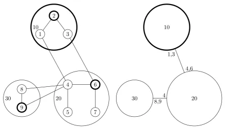
is the same as Di0, D0j (2.4) Fig. 2.1 shows an example of an Environment Composition: given three Atomic Environments (“1”, “2”, and “3”), and the new connections (1,2) and (2,3), the Composition result is an Environment that comprises all the Atomic Environments and the connections among them. Fig. 2.3 illustrates the composition result on top level.
Definition 10 (child/parent/sibling Environment) In a Composite En-vironment Env(V, E), if Vi ∈ V and Vi ∈ E, then Vi is a child
Environ-ment of Env and Env is the parent Environment of Vi. If Vi, Vj ∈ V and
Vi, Vj ∈ E, Vi, Vj are each other’s siblings.
Definition 11 (descendent/ancestor Environment) Descendent En-vironments of an Environment include: its children EnEn-vironments; and
the children Environments of any of its descendent Environments.
Ances-tor Environments of an Environment include: its parent Environment; and
the parent Environment of any of its ancestor Environments.
In other words, Environments that are not Atomic Environments are Composite Environment. The same condition as Equation (2.1) applies for Composite Environments.
These parameters can be aggregated effectively from the children Envi-ronments, without involving the parameters from lower level Environments. Each controller manages the aggregated parameters of its Composite Envi-ronment and the parameters of its children. When changes happen within an Environment, the changes propagate up to the top level Composite En-vironment. Threshold can be applied to reduce the change propagation of aggregated parameters.
2.2.2 Three Types of Environment Composition
As in the Definition 9, any output Environment comprises the same set of Atomic Environments and connections as input is a valid Composition. For the same input, there can be multiple valid Composition results. We categorize all the possible compositions into three types:
• Hierarchical Composition. The input Environments keep their
struc-tures, and form a higher level Environment. Each input Environment manages its children, and exposes its controller to others. Hierarchical Composition generates a loosely coupled Environment, having these benefits: a) it is easier to decompose into original input Environments; b) the communication within input Environments is efficient, because input Environment is tightly connected and remains unchanged in size; c) each input Environment retains control of its descendants. How-ever, the disadvantage is that the hierarchy is one more level deeper and the communication across input Environments is less efficient; and the composition algorithm is complex.
• Merge - under one controller. The input Environments break their
algorithm is simpler - we just need to rerun the composition algorithm. The disadvantage is that the output Environment is larger, has higher communication delay and is more vulnerable to controller failure.
• Merge - retaining multiple controllers. The input Environments break
their borders and form an Environment. All controllers of input En-vironments retain as controllers of the new Environment and share their control. This type of Composition has the following benefits: a) more robust to failure; b) controllers partially retain control; c) the communication is efficient in vicinity of a controller. However, it is more complex to set up and maintain the routing information of the network.
2.2.3 Routing in Composite Environment
In this subsection, we first show how a task is routed across Environments, then describe how the routing tables are created and managed during Envi-ronment composition and when the device connections are changed. Since our Environment model is hierarchical, we describe the composition on one level, and based on the assumption that: within any Environments (Ei),
the information is able to be delivered between any two children Environ-ments of Ei.
For simplicity, we introduce the routing in single controller Environ-ment. Routing in multi-controller Environment is similar except that mes-sage to an unknown destination is broadcast to all controllers of the Envi-ronment.
Fig. 2.2 shows our example of Environment composition.
Our routing is similar with traditional Internet routing protocols [70]. The differences include:
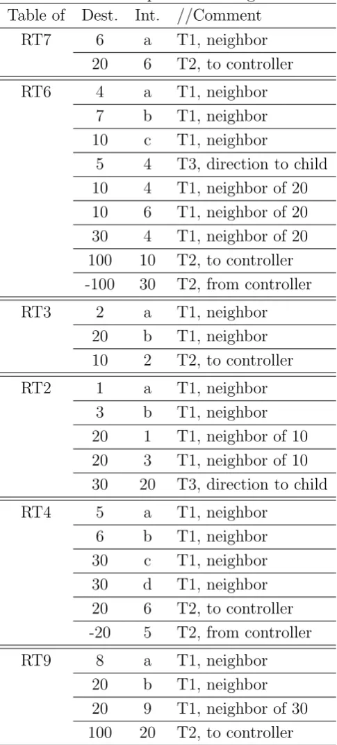
Table 2.1: Examples of Routing Tables Table of Dest. Int. //Comment
RT7 6 a T1, neighbor
20 6 T2, to controller
RT6 4 a T1, neighbor
7 b T1, neighbor 10 c T1, neighbor
5 4 T3, direction to child 10 4 T1, neighbor of 20 10 6 T1, neighbor of 20 30 4 T1, neighbor of 20 100 10 T2, to controller -100 30 T2, from controller
RT3 2 a T1, neighbor
20 b T1, neighbor 10 2 T2, to controller
RT2 1 a T1, neighbor
3 b T1, neighbor 20 1 T1, neighbor of 10 20 3 T1, neighbor of 10 30 20 T3, direction to child
RT4 5 a T1, neighbor
6 b T1, neighbor 30 c T1, neighbor 30 d T1, neighbor 20 6 T2, to controller -20 5 T2, from controller
RT9 8 a T1, neighbor
1 2 3 10 4 5 6 7 20 8 9 30
Figure 2.2: A more complex composition of Environments 10 20 30 1,3 4,6 4 8,9
Figure 2.3: The top level Composite En-vironment
its parent, children and siblings. So the routing is also not from any point to any point.
• Routing in Environments accompanies the Environment discovery. Besides pure message routing, our routing is concerned about the routing of tasks. Depending on task and Environment descriptions, decisions need to be made before routing to parent/child Environment.
• The Environments are not always well-connected. Because of the dy-namic nature of mobile devices, Environments and the connections are unreliable. The routing information needs to reflect the changes of connections in an efficient way.
Discovering a satisfying Environment
require-ment of a task. If yes, it passes the task to a satisfying child Environrequire-ment; If not, it passes to the parent Environment.
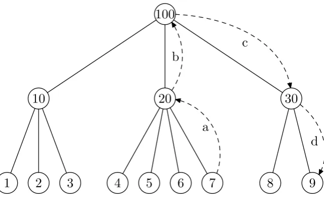
Our example is based on the completed Composite Environment as shown in Fig. 2.2. To better illustrate the process of discovering the Envi-ronment, we simplify the graph into a tree (Fig. 2.4). Each node in the tree is an Environment and its children nodes are the children Environments.
In the example, the Atomic Environment 7 generates a task, whose re-quirements are only satisfied on Environment 9. Here are the steps to discover the Environment (for convenience, when we say that an Environ-ment performs a certain action, actually its controller performs the action):
a. Atomic Environment 7 checks its capacity and capability and decides that it does not satisfy the requirements, then it passes the task to its parent Environment 20;
b. Environment 20 checks its aggregated parameters and decides that it does not satisfy the requirements, then it passes the task to its parent Environment 100;
c. Environment 100 satisfies the requirement, then it finds the satisfying child Environment 30 and passes the task;
d. Environment 30 finds the satisfying child Environment 9 and passes the task;
e. Environment 9 is the Atomic Environment that satisfies the require-ment, so it executes the task.
Routing across Environments
100
10 20 30
1 2 3 4 5 6 7 8 9
a b
c
d
Figure 2.4: Tree of Environments
each Atomic Environment has a Routing Table. The Routing Table also includes the information about the Composite Environment controlled by this controller, if any.
Definition 12 A link is the connection between two Environments. There are two types of links: Atomic Link is the connection between two Atomic
Environments; Composite Link is the connection between two
Environ-ments and at least one of them is Composite Environment.
A record in the Routing Table has two columns:
• Destination. The destination of a link. For an Environment, the visible destinations include: neighbors within the same Composite Environment (e.g., 4 knows 5 and 6); neighbors across Environment border (e.g., 4 knows 10 and 30); its controller (e.g., 4 knows 20 is via 6); paths to its children Environments (e.g., 20 (6) knows paths to 4, 5, 7).
• Interface. The next intermediate target that leads to the destination.
function Discover(Env, T) if Env.satisfies(T)then
return FindSatisfyingAtomicEnv(Env, T)
else if Env.hasP arent() then return Discover(Env.parent, T)
else
return null
end if end function
function FindSatisfyingAtomicEnv(Env, T)
if Env.isAtomic() then
if Env.satisf ies(T) then return Env
else
return null
end if end if
for all childEnv ∈Env do
if childEnv.satisf ies(T)then
re=F indSatisf yingAtomicEnv(childEnv, T)
if re6=null then return re end if
end if end for return null
end function
Table 2.2: Type of Routing Records
Type Description Type of Link Meaning Example T1 to
neigh-bor
Atomic Connection interface to the neighbor
4 to 5 via int. a
Composite The border Environ-ment that connects to the neighbor
20 to 30 via 4
T2 to/from controller
The next hop leading to the controller or the reverse direction
4 towards 20 via 6, and outwards via 5
T3 direction to child
The next hop from a controller to its child
20 (6) to 5 via 4, 100 (2) to 30 via 20
As shown in Table 2.2, there are three types of records in the Routing Table of a controller:
• T1, neighbor Environment. The connections between neighbor En-vironments define the whole network connectivity. For an Atomic Environment E, a link to a neighbor in the same Environment is an Atomic Link, and the corresponding T1 record points to the network interface that connects to that neighbor; and a link to a neighbor out-side the Environment is also an Atomic Link, but E only knows the Composite Environment that it connects (e.g., 4 only knows 10 and 30, but it does not know 8, 9, or 1). For a Composite Environment, the interface to a neighbor is its own child Environment on the border.
function GetNextHop(CurrentEnv, dest, source)
if dest==CurrentEnv then
next = SELF
else
interface = RT.lookup(dest)
if interf ace6=null then
next = interface
else if source==CurrentEnv.controller then
next = RT.lookup( - CurrentEnv.controller)
else
next = ERROR
end if end if end function
Figure 2.6: Algorithm: Find the next hop to route a message
the interface that goes away from the controller.
• T3, direction to each non-neighbor child, if the controller also controls a Composite Environment. When a controller sends a message to a non-neighbor child, it passes the message to a neighbor toward that direction. When an Environment on the path receives such a message addressing for another Environment, it passes the message to the out-ward direction. Then a controller is able to route a message to any child.
Setting up the Routing Tables
When several Environments are composing a new Composite Environment, connections are established in different levels of Environments. To repre-sent the new connections, records are inserted into the Routing Tables of the newly connected Environments.
The procedure can be divided into three phases:
• Connecting neighbor Atomic Environments. First, both Atomic En-vironments (e.g., 4 and 1) along the new connection insert a new T1 record containing the destination and interface information into their Routing Tables. However, the connection crosses the borders of ex-isting Composite Environments, and they (4 and 1) cannot see each other but only the top level Composite Environment that the other belongs. For example 4 sees 10 and 1 sees 20. So 4 inserts a record “10,c”, while 1 inserts “20,b”.
• Propagating neighbor connections to top level Environments. After
new connections are established in an Atomic Environment, this con-nection propagates to the parent Environment. The new record uses the child Environment who has propagated the connection as the in-terface, because the controller already knows the path to this child En-vironment. If the parent Environment has a parent Environment, the connection propagates further up to the top level Environment before composition. For example, the connection from 4 to 10 is propagated to its controller 6. A new record “10,4” is inserted into RT6. Since 6 is already one of the top level Environments before composition, the propagation stops here.
Figure 2.7: Initialization an Environment with no Controller
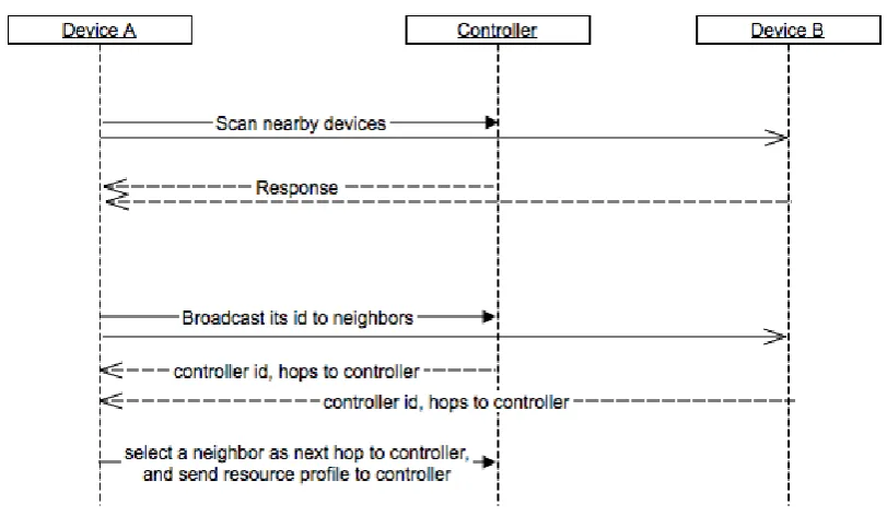
Figure 2.8: Join an Environment with Controller
Figure 2.8 shows the communication when a new device A finds an Environment with controller. Multiple neighbors can return a metric about the distance to controller. DeviceAselects one neighbor to connect. Figure 2.7 shows the communication sequence when a new deviceAdiscovers other devices in neighborhood but no controller is available. It is the procedure of setting up an Environment. Controller election algorithm is executed to elect a controller and set up the Environment. More discussion about election algorithm will be given later in this chapter.
Mobility Support
As we mentioned before, the challenges brought by mobile devices include:
• The wireless connections are unreliable. Many factors, such as
connection becomes invalid.
• The devices themselves are unreliable. When a device dies, the
con-nections linked to it becomes invalid. And the routing information that it holds is lost.
• The devices may physically move to different locations, changing the
connection topology. Even when the connectivity between devices remain unchanged, the movement of devices can cause the previous Environment Composition depreciated.
Our composition considers the above challenges by corresponding Rout-ing Table adjustment.
When the connection between two Atomic Environments is lost or a device is dead: The routing records are removed in the remaining Atomic Environments; If the connection crosses the Environment boundary and it is the only connection from the Atomic Environment to the top level neigh-bor, the controller of its parent Environment removes the record to that neighbor; If it is the only connection from the controller, the disconnected Atomic Environment asks all its neighbors for the distance to controller and pick the shortest as the new record, and propagates the same update along the previous path from controller; otherwise, the Routing Table of controller remains unchanged. If a controller becomes unreachable, a new controller is elected and the Routing Table is recreated by repeating the Routing Table setup process.
Envi-ronment. When the moved Environment was at the end of the path from controller, the procedure becomes simpler, because it is not affecting the T2 and T3 routing records of other Environments in the old Composite Environment.
Controller Election in the Composite Environment
The controller is a role in the Composite Environment. A child Envi-ronment serving as the controller of the Composite EnviEnvi-ronment has the following responsibilities:
• It calculates and maintains the composite capacity and capability for the Composite Environment as a whole. By aggregating the capacity and capability parameters from children Environments, the controller computes the composite parameters for the composite Environment. When a child Environment or the parent Environment passes a task with requirements on the capacity and capability of the Environment, the controller needs to check if the Composite Environment that it manages satisfies the requirements.
• It manages the index of capacities and capabilities of children
Environ-ments of the Composite Environment. If the Composite Environment satisfies the requirement, the controller needs to find out which child Environment satisfies the requirement. Then it passes the task to the satisfying child Environment.
message from controller. The controller only needs to know the first hop of the path that leads to each child Environment.
• It maintains the routing information to the neighbor Composite En-vironments. When the Composite Environment becomes a child of a higher level composite Environment, the controller needs to main-tain the information of routing information to the neighbor Composite Environment.
During the composition, a child Environment is elected as the controller of the Composite Environment. There are algorithms to elect the controller (coordinator) of a peer-to-peer network [35, 42, 97, 5]. Depending on the characteristic of the network, several factors can be considered:
• The availability of the controller. The availability of the controller is decided by its underlying Atomic Environment. If the availability of devices in the network is the major concern, we can consider the availability as the most important factor.
• (Degree Centrality) The connection degree of the controller. The
con-nection degree of the controller decides probability that the controller is connected to the rest of the Environment. In the network with het-erogeneous connections, we can attach weights to the connection to calculate the connection degrees. If the reliability of connections in the network is low, the connection degree can be the major concern in controller election.
When the communication delay or cost is the major concern, the aver-age distance to children Environments can be the factor that we need to consider.
These factors can be combined into a single metric to address multiple concerns in the controller election.
If we choose a metric that can be computed locally, e.g., the avail-ability or connection degree, we can use a flooding-based protocol: Each Environment computes its metric value and stores it in a buffer; Each En-vironment sends its metric to all the neighbors, containing its metric value and identity (ID); When an Environment receives a metric, if it is larger than current buffered metric, the Environment refresh the buffer with the greater value and sends the greater metric to all neighbors; otherwise, if the received value is smaller, the Environment discards the received met-ric; if the received value equals the buffered, the one with higher ID wins. At the end, each Environment buffers the greatest value of metric and the ID of that Environment. The election result is sent in broadcast in the Composition Environment, so each child knows the controller.
2.3
Environment Description Language
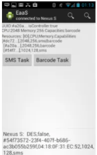
Figure 2.9: Console of a controller Figure 2.10: Barcode task received
Figure 2.11: Console of a child Figure 2.12: SMS task received
2.4
Implementation
We implemented a framework to verify the model and the algorithm de-sign. The framework design is divided into two related parts: the overlay network that manages the resources in Environments and routes process/-tasks, which was discussed in this chapter; the process engine on atomic Environment that executes the received process/tasks, which will be de-scribed in Chapter 4,
who is capable of reading barcodes, and Figure 2.11 shows a child Envi-ronment who is capable of sending message. In every EnviEnvi-ronment, a user can start a task of sending Short Message Service, or reading barcode, and the task will be routed to the Environment with required resources and executed (as shown in Figure 2.10 and 2.12).
2.5
Conclusion
Environment-as-a-Service
Architectures
In last chapter, we defined the model of Environment: a group of connected devices is modeled into Environment. Environment is the building block of our framework, and it is represented as a node in the graph. In this chapter, we are going to discuss the architecture to organize the Environments in the overlay network.
In this thesis, “architecture” refers to the overlay network structure on top of the physical network of devices. Devices can connect with each other using different types of links, such as Wi-Fi, Bluetooth, or wired connec-tions. We base the framework on transportation layer, taking advance of the existing connections for message exchange.
In the Environment-as-a-Service model, resources include the hardware capabilities and API access privileges on nodes. In the model, resources are described as tags. Routing information is the information about the connection topology. Depending on the routing mechanism, different infor-mation is collected and used for routing. For example, in centralized and hybrid architecture, the controller can maintain a map of destination-path; while in P2P architecture, each node can maintain a table of destination-nexthop.
We introduce different architectures of Environments, explaining the resource allocation and message routing approach.
3.1
Three Architectures
According to the connection topology among devices, there can be three different architectures: centralized (Fig. 3.1), peer-to-peer (Fig. 3.2) and hybrid (Fig. 3.3). By analyzing their network characteristics, we make the following analysis:
trivial here: each node just need to request the control to approve. However, this architecture is not scalable from the aspect of system performance. When the number of devices and users grows, it be-comes inefficient to manage the resources, and the network bebe-comes too large to perform routing efficiently; From the development effort aspect, it is easier to implement and the overhead of network setup is small.
2. Peer-to-Peer (P2P). There are no controllers in Environments. All children Environments share the information about resources and rout-ing in the Composite Environment. P2P architecture can either be flat, or hierarchical. In flat P2P architecture, there is only one Com-posite Environment containing all the children Environments. And each child shares part of the knowledge of resources and routing in-formation about other Environments. Hierarchical P2P architecture allows the composition of Environments, children Environments share the resource and routing information of the parent, but it only knows the aggregated information of its sibling Environments, but it does not know the descendant Environments inside the sibling Environments. P2P architecture is more robust to device or network failure due to the redundancy of connectivity and network management. However, the resource allocation can be slower and less effective, because no En-vironment has complete vision of resources and routing information. And the trust and authorize problem is more difficult to solve, because there is no central authority in the network in the initial state.
Com-posite Environment and the new controller is elected to manage the resource and routing at the new composed Environment. Devices de-ployed in vicinity are more likely to interact with each other in tasks, and they occasionally need to communicate with several devices far way. By dividing the network into sub-networks (Environments), hy-brid architecture can perform better on heterogeneous networks. Our first prototype adopts this architecture.
Because we are focusing on the deployment of task/process, the most important usage of the resources allocation and routing protocol is to route the task to the node with required capabilities. Considering the sequence of resource allocation and task routing, There are two possible designs:
1. Lookup a destination node first, and then route the task to that des-tination. The destination lookup and the task routing are separated. The framework first initiates the resource discovery algorithm, finds a destination node which satisfies the requirement. The result can be in the form of node ID, or a piece of routing information (e.g., a path) which leads to the destination. And then the task is routed to the destination node.
2. Lookup a destination and route the task at the same time. The task is also forwarded during the resource discovery process. When the framework finds the destination node with satisfying capabilities, the task is already at that node.
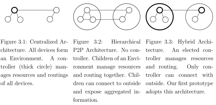
Figure 3.1: Centralized Ar-chitecture. All devices form an Environment. A con-troller (thick circle) man-ages resources and routings of all devices.
Figure 3.2: Hierarchical P2P Architecture. No con-troller. Children of an Envi-ronment manage resources and routing together. Chil-dren can connect to outside and expose aggregated in-formation.
Figure 3.3: Hybrid Archi-tecture. An elected con-troller manages resources and routing. Only con-troller can connect with outside. Our first prototype adopts this architecture.
3.2
Centralized Architecture
As shown in Fig 3.1, in centralized architecture, there is only one controller. The controller serves as the repository for resources on all devices, and manages the routing information for the whole network.
The setup of the centralized architecture is straight forward. A node is preconfigured as controller. Its ID can either be preconfigured in other nodes. It can also be broadcast in the network, given that the network is trustworthy.
3.2.1 Resources Management
During the setup phase of a node, it reports its available resources to the controller. The controller inserts it in the resource table.
3.2.2 Routing
Different routing mechanisms can be used in centralized architecture. The same routing mechanism described in last chapter also works under cen-tralized architecture: the controller knows the next hop for a destination, and a node knows the next hop to/from controller.
Another solution is to maintain the mapping of destination-path in the controller, and each node maintains the next hop to the controller. When a non-controller node receives a message, if the destination of a message is the controller, it passes the message to the next hop to the controller; if the destination is not to controller, the message contains a path from controller to destination, and the node just passes the message as instructed by the path. When a controller receives a message which is not addressed to itself, it attaches the path to the message and passes it to the next hop.
During the network setup phase, each node detects its neighbors and this information is flooded in the network. The controller collects the neighbor information of all the nodes and generate the graph of the whole network. Other routing protocols also work without treating the controller as a center. However, routing mechanisms which take advantage of the central controller are easier to implement and work better with the centralized resources allocation algorithm.
3.3
Peer-to-Peer Architecture
level node that satisfies the requirements, and then the same allocation algorithm repeats in that node, until the task is allocated to the satisfying atomic Environment.
3.3.1 Resources Management
There exist P2P resources management protocols [24, 5, 78, 74, 88, 101, 22]. One simple solution is to share all the resources information on each node. It is expensive to set up and maintain the complete resources index on each node. It generates more traffic to broadcast the resources information during the setup phase, and it occupies larger storage space to store the resource index. However, the resource discovery is fast, because it can be done on a single node.
More sophisticated protocols (for example Distributed Hash Table [9, 48]) can distribute resources allocation information multiple nodes. But the resources discovery need to communicate with other nodes and thus takes longer time.
3.3.2 Routing
3.4
Hybrid Architecture
Hybrid architecture implementation was described in detail in previous chapter. In hybrid architecture, each node implements the same set of functions and potentially can work as a controller. In each Environment, one node is assigned or elected as controller and manages the resources and routing. Our first version implementation adopts hybrid architecture. Hybrid architecture is easier to implement comparing to P2P architecture, because it can adopt simpler resources management and routing algorithm; and it is more scalable comparing to the centralized architecture, because the controller is a role that each node can take over.
3.5
Comparison
In this section, we compare the above three different architectures focus-ing on the aspect of resource management and message routfocus-ing. We first conclude the differences of architectures in Table 3.1.
Because centralized architecture and unstructured P2P architecture are more common and easier to understand, we focus on the comparison of hierarchical P2P and hybrid architecture.
Centralized Unstructured P2P Hierarchical P2P Hybrid Number of Overlay Network Level
one one multiple multiple
Controller one controller in the whole net-work
no controller no controller one controller in every Environ-ment Resource Allocation Informa-tion
in controller shared by nodes shared by chil-dren nodes of an Environment
in controller of an Environment
Routing by controller P2P protocols P2P protocols by controller
Table 3.1: Comparison of Architectures
architecture is easier to implement, because we do not need to manage the complex P2P protocols.
Since hybrid architecture and hierarchical P2P architecture have the same connectivity topology, we can use the same example network in Figure 2.2 to explain the different ways they handle the resource management and routing. Assuming that both architectures form the same overlay networks as shown in Figure 2.3, both architectures have the same resource tree as shown in Figure 2.4.
For example, hybrid architecture uses Environment 10 (the controller of whole composite Environment) to manage the resources (including re-sources on Environment 10, 20, 30). When the composite Environment (100) receives a task, the controller (10) is responsible to decide where (Environment 10, 20 or 30) to assign the task. Then the task is routed to the destination with the help of the routing information stored in the controller.
Environ-ment 10, 20 and 30 are shared among themselves. When a task is received, the P2P network formed by children Environments (10, 20, 30) of the com-posite Environment (100) is responsible to locate the destination to pass the task, using P2P protocols (such as flooding, or Distributed Hash Table [9]). The task routing is done either at the same time with destination lookup, or as the second step after the destination is known.
One common characteristic for hybrid architecture and hierarchical P2P architecture is that the nodes are organized in multiple levels. Resource management and routing are done first on separate levels, and then one level in if the destination is reached or one level out if the destination cannot be found. So the resource lookup and routing follows the same procedure in the resource tree in Figure 2.4: The framework will first decide which child Environment to look into, and then the task is passed one level down. If no child Environment satisfies the task, the task will be passed to the parent until to the top level Environment.
3.6
Justification of Adopting Hybrid Architecture
Deploying Processes and Tasks onto
Mobile Devices
In previous chapters, we described the model of Environment-as-a-Service and the architectures. With the resource management function, the frame-work can allocate the required resources in the composite Environment. With the routing function, any two nodes in the framework can communi-cate with each other. Process and task deployment are based on these two functions: we define a task’s requirements on resources and the resources availability in the Environment using the resource management function; and the communication for controlling the Environments and deploying the tasks are based on the routing mechanism.
In this chapter, we are going present how we deploy the processes and tasks, after they are assigned and routed to a destination Environment that satisfies the requirements.
without a central process engine, and executed in the destination Environ-ment by a lightweight process engine. On the framework level, a process is first deployed in a way similar to choreography: the deployment logic is predefined but a central process engine is not necessary; After a process is deployed onto the atomic Environments, the process engine executes the process or task on the devices which compose the atomic Environment.
We designed a lightweight process engine in atomic Environment, which executes the received process or task. The process engine supports the automatic assignment and distributed execution of tasks on wireless con-nected devices within an atomic Environment. The contributions of this chapter include:
• A mobile process management approach for design and execution of business processes on mobile devices. The approach is based on four phases: service preparation, process design, activity assignment and activity execution;
• An extension of the Business Process Model and Notation (BPMN)
2.0 specification [60] to allow context-aware activity assignment, par-ticularly: to model context constraints on activity assignment and execution, and model invocations of services offered by mobile devices inside business process models;
4.1
Scenario
Our motivating scenario for executing processes/tasks on mobile devices is from a real-world project called MOPAL [21] in which nurses deliver healthcare services at patient’s house with the assistance of mobile devices. The services are configured and monitored by a coordinator located in the hospital that schedules and assigns the healthcare services (i.e. a list of tasks for each patient) that nurses need to deliver. Task assignment considers criteria such as nurses’ qualifications, their location and service history in order to obtain the most efficient task execution and meet the requirements of the healthcare service.
The nurses receive the tasks and instructions elicited by a coordinator, such as the list of patients and the activities to perform on mobile de-vices through specific developed applications. One of such mobile-assisted healthcare service is given by the blood pressure examination. In such sce-nario the nurses use the mobile device to perform a set of tasks and collect patients’ blood pressure data through the following sequence of steps:
1. The application allows the nurse to search for a patient by the Social Security Number (SSN). It then loads patients data and shows them to the nurse.
2. The nurse, once measured the blood pressure enters the data filling specific forms.
3. If the pressure is too high, the application shows a warning mes-sage and suggests to the nurse to give to the patient an appropriate medicine. Otherwise this step is skipped.
5. After the nurse confirms, the report summarizing the set of activities is sent to the hospital.
6. Finally the coordinator can examine the activities and can update the task-lists for next visits.
Developing applications that support such care delivery scenarios is not cost effective and is time consuming because of the need to support many different healthcare processes and provide a high degree of customization. In our real-world project the design and development suffered many diffi-culties due to the need for flexible task definition, assignment and execution and frequent updates of the mobile applications on all mobile devices to ensure that all of them were running the last versions.
The task-intensive nature of analyzed healthcare services suggested the need for a more flexible assistance process definition approach using tech-nologies such as BPMN. Namely, process-modeling techtech-nologies such as BPMN have been demonstrated to provide an appropriate solution for fast changing contexts where the continuous evolution, monitoring and improvement of performed activities represent a crucial requirement.
A process model of the described blood pressure measurement service is shown in Figure 4.1. The coordinator’s lane defines the process of managing the health examination service, and it runs on the central process engine used by coordinators; nurses’ lane defines the process of carrying out the health examination, and it runs on mobile devices used by nurses.
Although it is very easy to model such healthcare delivery process, there are many challenges related to its potential execution on mobile devices that is still unsupported by current BPMN frameworks. To achieve the goal of business process assignment and distributed execution on mobile devices, we are facing several challenges:
ex-Hospit
al
Coordinat
or
Coordinator
Periodical control
Create health exam
ination task
Send the task
Close the task
Nurse
Nurse
Health examination
Receive the task
Measure blood
pressure too high?
Give medicine
Compose a report
Send response contraction>140
&&relax>90
ecution on mobile devices, as it does not exploit natively the func-tionalities and services offered by mobile devices. Such service can be any sensor-based collected information such as locations, network status or phone signal or it can be specific service such as Short Mes-sage Service (SMS) or calls that are present on mobile devices. The set of basic services that can be accessed by the process execution on a mobile device needs to be provided as a standard and lightweight library.
• Network connection on mobile devices is not always reliable (e.g. if the patients house is in a rural area). It is not acceptable to have loss of functionalities or latencies due to a disconnection of network. To tolerate the unreliable connection, the mobile process engine should be able to execute process and related tasks in an offline modality. Furthermore, it is needed a mechanism to prepare the required data before disconnection and to synchronize the data with the server once finished.
• Process and single activity assignments should be able to consider
context related information specific to mobile devices (e.g., current location of the nurse or required qualification). The modeling frame-work should support modeling of such context-aware constraints for activity assignment and execution on mobile device. It is important to exploit the available context information in order to assign the tasks in a smart and automatic way.
• The process models executed on mobile should be compatible with
cur-rent BPMN 2.0 specification while supporting extra defined semantics of constraints and services present on mobile devices.
engines is able to face the identified challenges and to provide a comprehen-sive solution to scenarios such as the one we faced in MOPAL project [21]. It is inefficient to run traditional process engines on mobile devices where computational resources are restricted. Mobile devices have slower CPUs, smaller Random-Access Memories (RAMs), and restrictions on energy con-sumption. Therefore a custom mobile engine and modeling framework is needed.
4.2
Mobile Process Management Approach
We tackle the previously described challenges by identifying a methodology that describes a sequence of steps performed by different participants each of them having different competencies and using different tools.
The four steps of our methodology identify the phases starting from requirements analysis to process execution. In particular it starts with the service preparation phase in which the developers prepare the services following the requirement analysis; then domain experts, with the help of developers, can compose and annotate processes on top of these services according to the business requirements; finally, the semi-automated assign-ment of tasks and process execution on mobile devices are performed by the framework.
4.2.1 Services Preparation