Virtual Laboratory Application Development
for Mobile Terminal
https://doi.org/10.3991/ijoe.v14i02.7779
Wenbin Zheng, Jinlong Shi, Jiaqing Qiao, Tian Xu, Lei Feng!!", Ping Fu
Harbin Institute of Technology, Harbin, China
Abstract—In order to confirm the theoretical knowledge it is important to perform experiments while learning the digital circuit design, which enhances the learning process. The digital design laboratories are often in short supply and introduces a number of limitations. The limitations includes smaller number of instruments and instrument stability, particularly in poor and developing countries. This paper reports the development of a mobile virtual laboratory ap-plication (VL-APP) digital design that help students to perform virtual experi-ments anywhere and anytime. It mainly utilizes simulation of experiexperi-ments and provides a model and script for users to design experiments independently. The development utilizes Unity3D and 3ds-max for the software platform, and An-droid for the test installation environment. The test results demonstrates poten-tial of the developed application.
Keywords—Mobile terminal; Virtual laboratory APP (VL-APP); Digital de-sign; Unity-3D
1
Introduction
Experiment is an essential part for theory tested not only in scientific research but also during daily study. With the rapid development of electronic technology, there appear more and more new devices or components and brand new circuits. The de-velopment of traditional electronic laboratory cannot be synchronized with the tech-nical needs. The conventional laboratories costs quite high and the cycle period is too long. It appears that the traditional electronic laboratory construction cycle is about two to five years and costing a lot of money, which is seriously restricting experi-mental teaching [1]. The emergence of virtual laboratories helped to avoid the draw-backs of the traditional laboratories [1-4]. Thanks to the new developments of com-puter technology.
Virtual lab is an open virtual experiment teaching system based on virtual reality (VR) which is the digitization and virtualization of traditional teaching labs. At pre-sent, virtual laboratories are well developed within the fields of biological, chemical, medical and even digital electronics laboratory are developed and implemented [4-7].
to a new era. Compared to the PC terminal, mobile terminal is more convenient, such as smaller and portable. The application of a large number of sensors which expands the boundaries of human-computer interaction makes an increase of user interaction with the software [1-3]. Rapid development of new mobile technologies, the infra-structure of communication information and of widely-accepted e-learning systems have made it possible to introduce a new paradigm in the field of distance learning which is denoted mobile learning or m-learning [2-4]. With the further development of hardware equipment of mobile terminals, a more excellent human-computer inter-action will make virtual laboratory applications on mobile terminals more widely used, and to realize the idea of "pocket lab," which introduces a new way of educa-tion.
The idea to build a mobile virtual laboratory comes from the observation of the be-ginners who are learning digital design course in several different forms of laboratory training in digital design. The traditional training takes place in a specially equipped laboratory where students model and implement digital circuit using breadboards and integrated circuit. The correctness of their design being verified on standard measur-ing instruments [3-9]. This form of laboratory trainmeasur-ing becomes increasmeasur-ingly ineffec-tive and time-consuming due to both a limited quantity of equipment and a large number of students.
Aiming at the beginners, the idea of a mobile laboratory for digital design is sup-ported by the need of virtual laboratory and the rapid growth of information and communication technology. It can carry out the phenomenon of circuit experiment demonstration and can complete the simple independent design experiment. It can greatly mobilize students to the extracurricular interest in learning and avoid the drawbacks of the limitations of the instruments.
Ruhr University in Germany built the virtual lab based on 3D vision simulation with complex teaching simulation equipment in the field of control area [7-10]. Bei-jing University built the virtual earth simulation laboratory for the experiment course in the field of earth [11-13]. Some other universities also built some virtual lab in mobile terminal such as Sumaya Princess University and Sagelebu University in Cro-atia [14-22].
Though all above have the disadvantages of simple function, specific applied field and so on. Based on current research result, we would like to design the mobile termi-nal APP, which is about the virtual experiments for the digital design course learning. In this field, there is no other APP and it would be very useful for all the engineering courses. The APP would more convenient and useful in and outside the class.
2
VL-APP Design Requirements Analysis
Software requirements analysis is the most critical part of the software lifecycle. Based on the requirements of virtual laboratory construction, this paper analyzes the overall framework of the virtual laboratory, analyzes the experimental requirements of the users and then analyzes the requirements of the software.
2.1 User Requirement Analysis
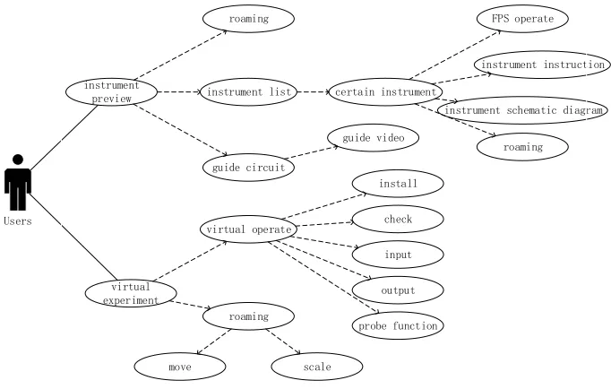
All the users could build circuits by using the experimental resources provided by the software which have the preview of experimental environment and instrument manual through loading the 3model of the component (like single chip, AD chip and etc.) or the instrument (like voltmeter, oscilloscope or digital monitor and etc. ) as the first personal sight. Users can view the instrument in the scene, in the virtual ex-perimental part of the instrument they can install instruments, select a different input signal by dragging other operations and observe the output phenomenon to complete the experiment without install or download any files. Figure 1 shows the user case diagram in detail.
Considering the users, the instrument preview module needs to be concise and de-tailed. We need to show the preview image of each instrument and give the users the option to view. After entering the detailed instrument display interface, the user will view the instrument's full-angle form and can drag manually rotate to view the in-strument in detail. The inin-strument description will also be provided to the user, such as function of every single chip pin and material of wires.
Experimental operation module is the core module of digital circuit design virtual laboratory. Experimental operation and experimental phenomenon display is the core function of the whole application. In this module, users can roam in experimental environment, acquire multi-angle view of the experimental platform, through the finger drag and drop to complete the chip installation and a series of experimental operations. The advantage of the mobile terminal sensor will provide the user a sense of immersion.
The experimental observation module allows the users to observe the experimental results by the indicator’s condition to verify the simulation results. Further, the digital design virtual laboratory provides a probe instrument that allows the users to use the probe to observe the level of each chip pin, which allows users to have more intuitive learning to understand the logic statement of the entire circuit and the function of each chip.
In general, the digital circuit design virtual laboratory helps the users to understand the basic components of the various digital circuit design and their use to build a sim-ple circuit. This help them to comsim-plete the experimental observation of the non through its two main function modules. Not only for the experimental phenome-non of simulation, it also allows users to build their own independent design of the circuit.
2.2 Performance Requirement Analysis
The performance requirements of this virtual laboratory includes the performance requirements, stability requirements and compatibility requirements of the software. The digital circuit design virtual laboratory reported in this paper is based on the mo-bile terminal. In terms of the performance requirements, there is strict control over the use of software storage, which is mainly reflected in the size of various types of in-strument model files in order to avoid excessive rendering of hardware resources.
In terms of the stability requirements, the problem of application crashes due to the misuse of the users, so the program jump, and system resources recovery could be prevented. This requires the software framework should be simplified during the UI design and focus on the resources used in the experimental operation module. At the same time, the runtime of the unity platform in the application would also monitor the software in the background, which will take self-correction program. In terms of compatibility requirements for the existing mobile terminal market and the commonly used operating system, the installation time, start time, resource share and other im-portant indicators of virtual laboratory should be better than the average. Then it would be suitable to apply in the real classes, otherwise, we would put more attention to optimize the codes in the APP to optimize the above parameters.
3
Development of the APP
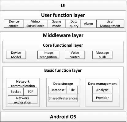
divided into four layers. These are- user interface layer, user function layer, middle-ware layer, and operating system layer. Among them, the middlemiddle-ware layer is divided into the core function layer and the basis function layer, as shown in Figure 2. Each layer is divided into modules. Every module is independent of each other and differ-ent modules are connected with each other through interfaces.
Fig. 2. Software module diagram
Our APP design is based on the Android operating system. The middleware func-tion layer provides the services such as network communicafunc-tion, data storage and data management. The core function layer provides the required equipment model, voice control, message push, data access agent and other core services to the user function layer.
3.1 Model Establishment
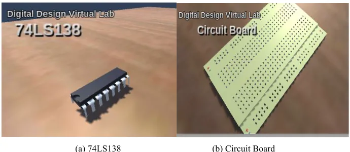
In this project, 3dsmax software is used to build the experimental components and instruments models, which are required for digital design experiments, including decoder chips, NAND chips, breadboards, wires and so on. These instruments vary in material including plastic, rubber, metal and glass. The simulation of these materials is to make the virtual laboratory looks more real as well as provide enough sense of immersion.
3dsMax software for used for digital circuit design, virtual laboratory information collection including the size of each experimental instrument and the relative size as well as the experimental instrument material characteristics. In the process, the de-tailed characteristics of each experimental instrument are described in details. Figure 3 shows the model of some circuit components, such as a decoder chip and the circuit board, which are established by 3dsmax.
!"# !$%&#'()*+,-)#./0%& !"#$%"&
%'()*'+ ./*#"$++0(%",$-"'& .%"("&1'-" 2/"*3!0)0& 4+0*1 70(08"1"()56"*&
1,22.%3/&%#./0%&
4-&%#'()*+,-)/.#./0%& !"#$%"&
7'-"+ %'()*'+,'$%"& 7"6608"&9/6:
5/$,*#'()*+,-)#./0%&
6%+3-&7#
*-88(),*/+,-) 9/+/#$+-&/:% 9/+/#8/)/:%8%)+
;")<'*=& ">9+'*0)$'( .'%=")
.:0*"-?*"@"*"(%"666
.:0*"-?*"@"*"(%"6
4(0+36$6
?*'#$-"*
;)2&-,2#<= A108"&
*"%'8($)$'(
(a) 74LS138 (b) Circuit Board
Fig. 3. Model of Circuit Component
After the establishment of the models, we need to import them to the unity plat-form for the beautification of the texture map and the construction of the experimental scene, making them virtual objects that can be called and processed. Then add dynam-ic components and custom components to complete the virtual object between the human-computer interaction, element interaction and visual interaction, and thus build a virtual laboratory system.
3.2 Roaming and Instrument Display
Roaming system is to create a virtual information environment in the multi-dimensional information space allowing users to have a sense of immersion with the environment and the ability to interact and help to inspire ideas. By placing the FPS Controller component and compiling it. When the application is running, the users can roam in the scene. FPS Controller audio function also makes some of the sound during the experiment simulated. The experiment instrument automatically rotates and displays the label when each scene is not awakened by the mouse click or finger touch. The label display script is to make the camera elements radiate by editing the FPS Controller and add the Box Collider component to each instrument in the scene so that it can reflect the rays to determine the position coordinates of the object.
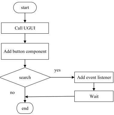
3.3 User Interface Design
start
Call UGUI
Add button component
search Add event listener
Wait
end
yes
no
Fig. 4. System workflow of interface design
3.4 Simulation of experimental operation
Unity3d programming is an object-oriented operation. Therefore, for different ex-perimental instrument models, we need to have different script components to edit the various functions they should have. Different instruments may have different scripts, they can also share the same script and finally under a unified control trigger script, the action of the instruments can complete the experiment with each other. This digi-tal design virtual laboratory involves a number of operations including click, drag, slide, scaling, press and so on. For application on mobile terminal, we use ray colli-sion method. For touch operation of scene scaling, we need to use the ‘Input.touches’ function in the Unity3D API. The ‘Input.touches’ structure is a touch array and each record represents the touch state of the finger on the screen. By recording the change offset of these states, the latest coordinates are assigned to the controlled object so that the scaling operation is done.
3.5 Simulation Results
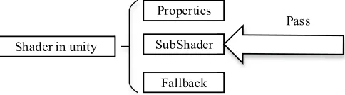
Figure 5 shows the basic framework of Shader program. We recompile the proper-ties and sub-Shader set the main color, diffuse color, luminous co-efficient and other parameters.
Shader in unity
Properties
SubShader
Fallback
Pass
Fig. 5. Shader framework
3.6 Simulation of instrument logic function
The digital design virtual laboratory is not only for a single digital logic circuit simulation but also for the simulation of various logic devices output. Such as wire ends at the same level and the differing output of probes. That is to say, this digital design virtual laboratory provides a basis for function expansion. In the Unity3D platform, Rigid body and collider are the most commonly used physical properties of objects and are the most flexible components. In this work, we use the existence of collider instead of the level. Rigid body and collider combination can produce colli-sion events and trigger events, which are used by the virtual laboratory experiment to complete the simulation.
When users switch to a certain input state, the input pin of the chip will produce a collider and by the collider trigger the chip output pin will produce the corresponding collider through the wire transfer and finally reach the output. When the indicator light detects the collider, the probe lights up. After the experimental phenomenon observation, users can use the light-emitting probe to check the experimental process of each point of the logic input and output. It would be guided to think about the prin-ciple design of this logic circuit.
4
Functional Test
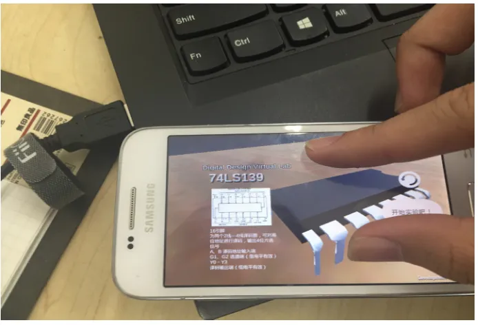
After setting the software resolution and the horizontal screen mode of operation, the software could be packaged into APK files, which could be installed in the An-droid mobile terminal. Figure 6 shows that the software runs smoothly on mobile terminals so that all of the device models can be displayed properly.
Figure 7 shows the mobile terminal allows users to implement touch operations such as moving and scaling.
Fig. 6. Interface shown on mobile terminal
4.1 Experimental demonstration function
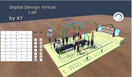
After the circuit is built completed by choosing all the components from the com-ponents library, users can switch the different input state to observe the experimental phenomenon in this experiment. Figure 8 shows a certain output of the digital circuit. According to the full adder truth table, when the input terminals B2, B1, and B0 are selected as "1, 1, 1", all of the indicators are in right condition.
4.2 Probe detection function
In the virtual experiment scene, there are two upper and lower probes available to the users. Users can move them to any position of the board to detect the level state. Figure 9 shows both of the indicators light up when the input condition is selected as “1,0,1”.
Fig. 8. Test of experimental demonstration function
5
Performance Test Result
With the help of Baidu MTC test platform, we have a deep test of the software. In terms of compatibility, the pass rate is 90.9%, which is better than most similar kinds of software. Table 1 shows the details of the compatibility test, the result comes out to be in the upper standards.
Table 1. Compatibility test
Conclusion Quantity Success Dead start Crash UI fault
Terminal types 22 20 2 0 0
Rate 100% 90.9% 9.1% 0 0
Users influenced 290k 260k 20k 0 0
Average - 89.2% 0.2% 1.5% 1%
Figure 10 and Figure 11 show that the usage of CPU and storage ram of the virtual laboratory by different kinds of mobile terminal. It shows for 21 different kinds mo-bile terminals. There would all cost lower than 40% of CPU and about half cost lower than 25%. It shows that our APP would have a smooth experience during using. All of the mobile terminals would cost no more than 200 MB. It would be perfect to use our APP as most terminals would have at least 2GB ram in it. Since the software is packed with a guide video and several device models, it is reasonable for it to occupy more storage. As our APP progress, I think it would be still have a good performance in the future.
Fig. 10.Usage of CPU
32.81-38.78 26.84-32.81 20.88-26.84 14.91-20.88 8.94-14.91 0
1 2 3 4 5 6
5
4 4
3
5
CPU Occuptation %
Num
be
r of
M
obi
le T
er
m
in
al
Fig. 11.Usage of RAM
6
Conclusions
This paper designed the digital laboratory VL-APP demonstration software on the mobile terminal based on the actual project requirements. Through the background information query application research, we are introduced the development of mobile terminal virtual laboratory. Taking the functional requirements, user needs and per-formance requirements of the software and software architecture into account, we select the right development plan to carry out.
According to the requirement analysis, we completed the modeling work and inter-active design to set up a virtual experimental scene. By code compilation, we give the instrument complete logic function which allows the software not only complete the experimental phenomenon demonstration function but also provide the basis for inde-pendent design experimental function expansion.
After the construction of the software, we have the virtual laboratory functions tested on Android mobile terminals. With the help of MTC test platform, the compat-ibility and performance of the software are shown in detail, which turn out to be in the upper level. In the future work, the virtual laboratory will expand the function of demonstration of other circuits, offer users’ authority to design the circuit in order to verify their thoughts.
156.2-194 118.4-156.2 80.6-118.4 42.8-80.6 5-42.8 0
2 4 6 8 10 12
4 4
11
1
2
RAM Occuptation MB
Num
be
r of
M
obi
le T
er
m
in
al
s
7
Acknowledgment
This work is supported in part by the Online Education Research Funds of Online Education Research Center of Ministry of Education (Quantong Education) (Grant No. 2016YB132), CERNET Innovation Project (Grant No. NGII20160610), “the Fundamental Research Funds for the Central Universities” (Grant No. HIT NSRIF.20169) and Heilongjiang Postdoctoral Fund (Grant No. LBH-Z16081).
8
References
[1]Fang Qin, Design and Implementation of Virtual Laboratory Based on Unity3d and 3dsmax, Beijing: Beijing University of Posts and Telecommunications, 2012.
[2]Liu Xiaolan, “The Types and Development Trend of Virtual Labs,” in Journal of Comput-er Applications, vol.11, pp: 8-10, 2004.
[3]Liu Zhe, Research on Virtual Laboratory of Titration in Mobile Terminal, Dalian: Dalian University of Technology, 2015.
[4]Vlado, Glavinic. “Mobile Virtual Laboratory: Learning Digital Design,” in Proceedings of the ITI, 29, pp: 325-332, 2007.
[5]Mwikirize C, Tumusiime A A, Musasizi P I, et al. New Dimensions in Teaching Digital Electronics: A Multimode Laboratory Utilizing NI ELVIS IITM, LabVIEW and NI Multi-sim [J]. International Journal of Online Engineering, 2010, 6(4). https://doi.org/10.3991/ ijoe.v6i4.1396
[6]Luo W, Liu C, Zhao E, et al. The Implementation of the VRML-Based Digital Circuit Vir-tual Experiment[C]// International Conference on Wireless Communications NETWORKING and Mobile Computing. IEEE, 2010:1-4.
[7]Karmakar S. Virtual-Instrument-Based Online Monitoring System for Hands-On Laborato-ry Experiment of Partial Discharges [J]. IEEE Transactions on Education, 2017, pp. (99):1-9.
[8]Yang Chuang, Water network detection server and mobile terminal software construction, Harbin: Harbin Institute of Technology, 2016.
[9]Bai Yan, “The Application of Virtual Laboratory in Analytical Teaching in Colleges and Universities,” in Experimental Technology and Management, vol.28, pp.170-174, 2011. [10]Wang Qing, “Talking about the development space of mobile phone VR from VR
glass-es,” in Technology vision, vol.10, pp. 58, 2010.
[11]Gan Maohua,”Multi - person Collaboration Virtual Laboratory,” in Computer Applications and Software, vol. 27, pp. 131-143, 2010.
[12]Yin Mengzheng, “Summary of Android - based App Development Platform,” in Commu-nication power technology, vol. 33, pp. 155-213, 2016.
[13]Chen Kejian, Construction of Virtual Experiment of Multivariate Modular Molecular Spectral Series, Dalian: Dalian University of Master Degree
[14]Chen Xiaohong, “Research Status and Development Trend of Virtual Laboratory,” in Chi-na Education Equipment, vol.17, pp. 170-179, 2010.
[15]Bao Hujun, “The Development and Present Situation of Virtual Reality Technology,” in Computer society newsletter, vol. 6, pp. 13-16, 2010.
[17]Ju Pinghua, Research on Virtual Laboratory Based on Virtual Instrument, Chongqing: Chongqing University, 2005.
[18]Zhao Qinping, “Summary of Virtual Reality,” in China Science. Vol. 29, pp. 2-46, 2009. [19]Liu Shiwei, “Research and Application of Virtual Laboratory,” in Internet Technology,
vol. 9, pp. 82-83, 2016.
[20]Yi-Hsung, Li, “A systematic framework of virtual laboratories using mobile agent and de-sign pattern technologies,” in International Journal of distance education technologies, vol.7, pp. 26-43, 2009. https://doi.org/10.4018/jdet.2009070102
[21]Chyi-Ren, Dow, “A virtual laboratory for digital signal processing,” in International jour-nal of distance education technologies, vol.2, pp. 31-43, 2006.
[22]Akram, Alkouz, “J2ME-based Mobile virtual laboratory for engineering education,” in In-ternational Journal of Interactive mobile technologies, vol.2, pp. 5-8, 2008.
9
Authors
Wenbin Zheng is a lecturer of School of Electrical Engineering, Harbin Institute of Technology, No.2 Yikuang Street, Harbin, Heilongjiang Province, China, 150080. He received doctorate degree in 2014 from Harbin Institute of Technology. His main research interests are cooperative transmission, wireless sensor, network and automat-ic test and control technology, mautomat-icro-fluidautomat-ic technology, etc.
Jinlong Shi is a Doctorate degree candidate of School of Electrical Engineering, Harbin Institute of Technology, No.2 Yikuang Street, Harbin, Heilongjiang Province, China, 150080. He received Master’s degree in 2013 from Harbin Institute of Tech-nology. His main research interests are wireless sensor, automatic test and control technology, Android application development, etc.
Jiaqing Qiao is an Associate Professor of School of Electrical Engineering, Harbin Institute of Technology, No.2 Yikuang Street, Harbin, Heilongjiang Province, China, 150080.
Lei Feng is an Associate Professor of School of Electrical Engineering, Harbin In-stitute of Technology, No.2 Yikuang Street, Harbin, Heilongjiang Province, China, 150080.
Ping Fu is a Professor of School of Electrical Engineering, Harbin Institute of Technology, No.2 Yikuang Street, Harbin, Heilongjiang Province, China, 150080. He received his Doctorate degree from Harbin Institute of Technology in 1999. His main research areas are image processing, compressive sensing and automatic test technol-ogy, etc.