Performance evaluation of a hand pump with provision of a
sealed secondary water sump
Amaresh Sarkar
*, Madan Kumar Jha
(Agricultural & Food Engineering Department, Indian Institute of Technology Kharagpur, Kharagpur, PIN – 721 302, West Bengal, India.)
Abstract: Nowadays, a large number of water lifting devices and pumps are available for lifting water or other liquids from a lower elevation to a higher elevation. However, none of the available hand pumps use a secondary water sump or any other such kinds of devices which increase the efficiency of hand pumps. Also, measurement of operating forces during performance evaluation of hand pumps is often missing. In this study, a commonly used hand pump was fitted with a 54-liter capacity sealed secondary water sump and its performance was evaluated. The secondary water sump was linked with the shallow well which served as the source of water during experimentation. The experimental results indicated that the provision of a secondary water sump for a hand pump results in a significant reduction in the input power; thereby it requires lesser operating force. The experiments also revealed that the secondary water sump of larger capacity requires lesser force to operate the pump. However, the output powers in both the cases viz., with and without secondary water sumps were found to be approximately same. It is concluded that the provision of a secondary water sump fitted with a hand pump provides more comfort in operating hand pumps.
Keywords: Hand pump, secondary water sump, pump efficiency
Citation: Sarkar, A., and M. K. Jha. 2015. Performance evaluation of a hand pump with provision of a sealed secondary water sump. AgricEngInt: CIGR Journal, 17(3): 166-175.
1 Introduction
1Hand Pumps have been given a high profile in the
quest to provide potable water to the world's burgeoning
rural population by leading players in development like
the World Bank, UNICEF and a plethora of international
non-government organizations (Parry-Jones et al., 2001).
Hand pumps are low-speed pumps. They vary in their
design; however, most of them are positive displacement
pumps and have reciprocating pistons or plungers. (Lal,
1969; Michael and Khepar, 1999).
A state-of-the-art review of hand pump designs is briefly
discussed here. Force and Lift Hand Pump is a suction
pump which can draw water from up to 8 m depth and
can lift up to 10 m delivery head (AIC, 1961). Shallow
Received date: 2014-10-03 Accepted date: 2015-08-04
*Corresponding author: Amaresh Sarkar, Department of Agricultural Engineering, College of Agriculture Tripura, Lembucherra, Agartala, PIN –799 210, India. Tel: +91-9436349675. E-mail: [email protected]
Well Hand Pump is used to lift water from a max depth
of 7 m (SKI, 1961). Tara Direct Action Hand Pump is
designed by UNICEF is designed for lifting water from
bore wells with the static water level not exceeding 15 m
(SKI, 1961). Diaphragm Hand Pump was originated in
France and was developed by Vergnet S.A. It is also
known as Vergnet Hand Pump. The pump is powered by
foot using a pedal (WA, 1981). Non-Piston Pump is a
high lift and mono progressing cavity hand pump (WA,
1981). Extra Deep Well Hand Pump is exclusively used
for extracting water from greater depths. It is also called
Meera Vlom India Mark IV. It is suitable for static water
levels varying from 50 to 90 m (AOVI, 1982). India
Mark III Deep Well Hand Pump is an improved version
of VLOM (Village Level Operation and Maintenance)
version of the India Mark II Hand Pump (AOVI, 1982).
Rower Pump is a manually operated, suction piston
pump used for drawing water from low-level springs,
shallow wells, river beds and open water (SWSFL, 1982).
up to 60 m depth (CWWHP, 1983). Afripump is based
on the Volanta Pump technology and also called
Volanta-Afripump (WC, 1986). Awassa Hand Pump was
initially designed in Ethiopia in 1988. The pump
basically consists of a drive unit and a pump unit
connected by flexible plastic piping and works by
hydraulic action (NRCC, 1988). Rope Pump consists of
a loop of nylon rope with rubber gaskets attached to it. It
is manually operated by rotating a wheel, which pulls the
rope through the pipe (TTD, 1990). Volanta Flywheel
Hand Pump was developed by Jansen Venneboer, which
is used for community water supply and is suitable for
lifting groundwater from up to 100 m depth. The pump
is manually operated with a large flywheel (JVBV,
1990). Inertia-Lift Village Pump is neither a piston nor a
vacuum pump. Water is delivered on both up and down
strokes (EZIA, 1991). Bush Hand Pump can be used for depths up to 100 m. It is also called “POV-RO 2000 Pump” in Nepal, “Zimbabwe Hand Pump” in Zimbabwe, and “Bush Pump” in Liberia (LC, 1998).
1.1 Advantages of hand pumps
The main advantage of hand pumps is that they are
one of the most economical and simple solutions for
providing a collective supply of drinking water in rural
areas and suburban environments. They also help to
eliminate the risks of people, and children, in particular,
falling into open wells. They also improve the conditions
of hygiene under which water is drawn off, by
eliminating the use of buckets of uncertain cleanliness,
thereby limiting diseases associated with contaminated
water.
1.2 Price of hand pumps
The criteria for choosing a hand pump should be
based on the possibility of easily finding spare parts and
people able to maintain or repair it. There will thus be a
need to first gather certain information such as the pump’s type use for family, small community, village,
the depth of the well or borehole, the delivery head, the
desired pump flow rate, the price range acceptable to the
community. Indeed, the price of hand pumps varies,
depending on the way they are manufactured, their use
and their resilience. Their price also most often varies
according to the depth of the well or borehole and the
country.
1.3 Community involvement in maintaining hand
pumps
The user involvement is vital for the long-term
effectiveness of hand pumps. The best way to achieve
this is by the appointment of a pump caretaker among
the pump users who is self-motivated, after proper
training and the supply of a tool kit, will carry out the
duties namely to perform regular inspections daily, to
train people how to use the pump properly, to make
simple repairs or replacements, to keep a supply of spare
parts, and to ensure that surplus water is drained away
(World Bank, 1986)
1.4 Objective of the Study
The extensive review of literature revealed that a large
number of hand pumps designs are available for lifting
water from a lower elevation to a higher elevation.
However, none of these hand pumps uses a secondary
water sump or any such kind of device which increases
the efficiency of hand pumps. Therefore, the present
study was carried out with the following objectives: (i)
to evaluate the performance of a hand pump fitted with a
sealed secondary water sump under different suction
heads, and (ii) to evaluate the effect of the capacity of
secondary water sumps on the hand pump performance.
It is evident from literature review that the present study
is a novel one. The finding of this study is of great
importance because the proposed improvement in the
hand pump system is expected to provide an efficient
design of widely used hand pumps.
2 Materials and methods
2.1 Working principle
At the beginning of pumping, water was delivered
from the secondary water sump which is placed at the
ground surface or just below the ground surface. Hence,
is very low. In this situation, when the negative pressure
inside the air tight secondary water sump becomes more
than the minimum suction force to lift water from the
primary water sump due to water withdrawal by
pumping, then the non-return valve of the secondary
water sump gets open and water from the primary water
sump is lifted to the secondary water sump continuously.
In this way, in every 10 to 12 pumping complete strokes
(comprises one upward stroke and one downward stroke
of the piston) interval, water is lifted to the secondary
water sump from the primary water sump. Thus, no
additional force is directly required to lift water from the
primary water sump to the secondary water sump.
Therefore, the operating force of the hand pumps fitted
with a secondary water sump is very less in comparison
to that without a secondary water sump.
2.2 Experimental setup
To ensure the viability of the proposed design of the
improved hand pump system, an experimental setup was
developed in the Field Water Management Laboratory of
Agricultural and Food Engineering Department, Indian
Institute of Technology Kharagpur, West Bengal, India
located at 22° 20' 23” N latitude, 87° 19' 30” E longitude
and 37 m altitude from mean sea level. The experimental
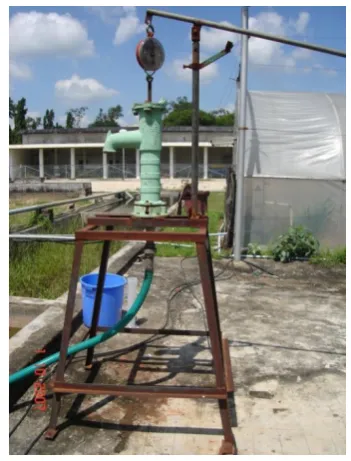
setup consisting of a shallow well hand pump, a
secondary water sump fitted below the suction port, and
a tension dynamometer fitted between the handle and top
of the piston rod is shown below in Figure 1(a) and the
experimental setup without fitting any secondary water
sump is shown in Figure 1(b). The experimental site has
flat topography with fine loamy soil. The inner diameter
of the experimental open well is 2.4 m and depth is 7 m,
with a masonry lining wall. The open well has provision
of electric operated pump for quick water lifting and
refilling for experiments with different suction heads.
Figure 1(a) Experimental setup of the hand pump fitted with a 54-L MS secondary water sump
Figure 1(b) Experimental setup of the hand pump without a secondary water sump
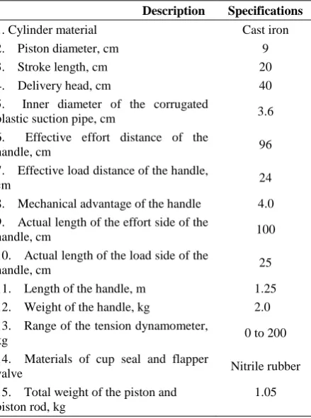
The specifications of the hand pump and its
accessories used in experiments are given below in Table
1. Experiments were conducted on the hand pump
without a secondary water sump as well as with a
54-liter metallic secondary water sump made of mild
steel (MS) and a 25-liter metallic secondary water sump
made of galvanized iron (GI) by pumping water from
different suction heads of an open well having maximum
depth of 7 m. Actual operating force, time and volume of
suction heads were recorded. Five sets of these
measurements were taken for each static suction heads.
Discharge per downward stroke was also recorded. Operator’s body weight was 58 kg and the same operator
was used for the entire pumping operations with usual
normal strokes by using a single hand for static suction
heads of 1.0 m to 3.5 m and double hand for static
suction heads of 4 m to 6 m.
Table 1 Specifications of the hand pump setup
Description Specifications
1. Cylinder material Cast iron
2. Piston diameter, cm 9
3. Stroke length, cm 20
4. Delivery head, cm 40
5. Inner diameter of the corrugated
plastic suction pipe, cm 3.6 6. Effective effort distance of the
handle, cm 96
7. Effective load distance of the handle,
cm 24
8. Mechanical advantage of the handle 4.0 9. Actual length of the effort side of the
handle, cm 100
10. Actual length of the load side of the
handle, cm 25
11. Length of the handle, m 1.25 12. Weight of the handle, kg 2.0 13. Range of the tension dynamometer,
kg 0 to 200
14. Materials of cup seal and flapper
valve Nitrile rubber
15. Total weight of the piston and piston rod, kg
1.05
Randomly chosen 54 liters capacity secondary water
sump (SWS) made of mild steel and 25 liters capacity
water sump made of galvanized iron are shown in Figure
2(a) and Figure 2(b), respectively. The specifications of
the two secondary water sums are summarized below in
Table 2. The 54 liters capacity cubical secondary water
sump was locally fabricated with an outer dimension of
38.12 cm × 38.12 cm × 38.12 cm, wall thickness 3.18
mm and has four extended legs at the bottom four
corners. In the 54-liter SWS, the inlet is fitted upward at
the center of the bottom surface and an outlet is fitted
downward at the top surface. The 25 liters capacity
cylindrical sump was chosen from locally available
sumps with 27 cm diameter, 1.27 mm wall thickness and
has no extended legs at the bottom surface. In the
25-liter capacity SWS, the elbow inlet and outlet pipe
were fitted upward at the top surface because of not
having any extended legs and difficulty to fit extended
legs over the low wall (surface) thickness. Both the
secondary water sumps have one inlet and one outlet,
both fitted with 32 mm inner diameter GI pipe of 3.2 mm
2.3 Measurement of operating forces
The actual force required to raise the piston can be
measured directly from a tension dynamometer which is
fitted in between the top of the piston rod and the handle.
The handle of a hand pump works as a first class lever.
Therefore, the force required to raise the piston is more
than the force applied to the handle. Thus, the actual
force required to the handle was calculated as:
aus ah
F
F =
MA
(1)Where, Faus = actual force required during upward stroke
(N); Fah = actual force required to the handle during
upward stroke (N); and MA = mechanical advantage of
the handle (dimensionless).
The actual force required to lower the piston (i.e. to raise
the handle of the hand pump) during downward stroke
was calculated as:
Fads = Weh – (Wlh + Wp) (2)
Where, Weh = weight of effort side of the handle (N);
Wlh = weight of load side of the handle (N); and Wp =
weight of the piston and piston rod (N).
The weight of effort side and load side of the handle was
calculated as:
eh h
a
W
(W )
(a+b)
(3)lh h
b
W
(W )
(a+b)
(4)
Where, a = actual length of the effort side of the handle
(m); b = actual length the load side of the handle (m);
and Wh = total weight of the handle (N).
2.4 Calculation of discharge and volumetric efficiency
The actual volume of water delivered per 10 strokes
was collected in a bucket and then measured by using
measuring cylinders. The volume of water to be
delivered in an upward stroke of the piston is equivalent
to the swept volume of the piston. Similarly, in a
downward stroke of the piston, a stroke length
equivalent distance of the piston rod is immersed in
water; as a result an equivalent volume of water gets
displaced as discharge. This volume of water delivered
Figure 2(a) 54 liters capacity SWS; Figure 2(b) 25 liters capacity SWS
Table 2 Specifications of the secondary water sumps used in the study
Sl. No. Capacity, L Material Shape Outer Dimensions, cm Wall Thickness , mm
per downward stroke of the piston is very less in
comparison to the volume of water delivered per upward
stroke of the piston. The theoretical volumes of water
delivered in an upward stroke and in a downward stroke
were calculated as (Lal, 1969; Michael and Khepar,
1999):
Vus = (Ap-Ar) S (5)
Vds = Ar S (6)
Where, Vus= theoretical volume of water delivered
during an upward stroke (m3); Ap = cross-sectional area
of the piston (m2); Ar = cross-sectional area of the
piston-rod (m2); S = stroke length of the piston (m2); and
Vds = theoretical volume of water delivered during a
downward stroke (m3).
Therefore, the theoretical total volume of water
delivered in a complete stroke (one upward and one
downward) is:
Vt = Vus + Vds (7)
Where, Vt = theoretical total volume of water delivered
per stroke (one upward and one downward) of the piston
(m3).
Moreover, the volumetric efficiency of a hand pump was
calculated as (Lal, 1969; Michael and Khepar, 1999):
a Vol th
V
100
V
(8)Where, Va = actual volume of water delivered in a
complete (one upward and one downward) stroke (m3);
and Vth = theoretical volume of water delivered in a
complete stroke (m3).
2.5 Calculation of input power, output power, and
overall efficiency
One complete stroke (one stroke) of the hand pump
comprises one upward stroke and one downward stroke
of the piston. The duration of one upward stroke is the
time required to move the piston from bottom dead
center to top dead center in the piston cylinder. Similarly,
the duration of one downward stroke is the time required
to move the piston from top dead center to bottom dead
center in the piston cylinder. In an upward stroke, the
piston works for water suction force and against piston
friction and gravity. However, in a downward stroke, the
piston works against piston friction towards gravity only.
Therefore, the force required in a downward stroke of
the piston is very less in comparison to an upward stroke
of the piston. Each upward stroke is always followed by
one downward stroke. The frequency of strokes of any
hand pumps may be estimated as the number of
complete strokes per unit time. The ‘input power’, ‘output power’ and ‘overall efficiency’ of the hand pump
was calculated as:
aus ads
i
us ds
F
F
P =
S
T
T
(9)o t aus ads
P =
(Q
Q
(10)o overall i
P
=
100
P
(11)Where, Pi = input power to the hand pump (W); Po=
output power of the hand pump (W); η overall = overall
efficiency of the hand pump (%); Faus = actual force
required during an upward stroke (N); Fads = actual force
required during a downward stroke (N); Tus = duration of
one upward stroke (s); Tds = duration of one downward
stroke (s); Qaus = actual volume of water delivered in an
upward stroke (m3); Qads = actual volume of water
delivered in a downward stroke (m3); = specific
weight of water (N/m3); Ht (total pumping head) = Hs
+Hd + Hf (m); Hs = static suction head (m); Hd = static
delivery head (m); and Hf = major and minor friction
head losses on the suction and delivery sides (m). The
friction head losses due to roughness of the inner surface
fluid, etc. for a hand pump system are practically
negligible because of low flow rate of water and hence,
they were not considered during total head calculation.
2.6 Evaluation of the effect of secondary water sump
capacity on the pump performance
The effect of different sizes/capacities of secondary
water sumps on the performance of a hand pump was
assessed by comparing the results of the experiments of
hand pump fitted with a randomly chosen 54 liters
metallic (MS) and locally available 25 liters metallic (GI)
secondary water sumps.
3 Results and discussion
3.1 Performance of the hand pump with 54-liter and
25-liter secondary water sumps
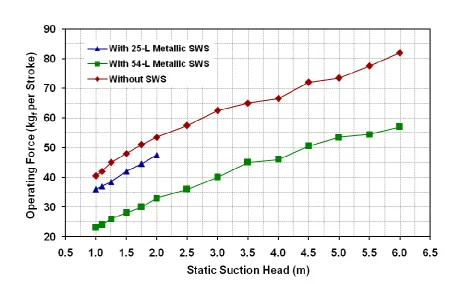
The experiment on the hand pump with a 54 liters
metallic secondary water sump revealed that the pump
was able to lift water up to 6.0 m static suction head
(Figure 3). However, the experiment on the hand pump
with a 25 liters metallic secondary water sump was done
mainly to check the effect of capacities of secondary
water sump on the hand pump performance. Therefore,
the experiment on the hand pump with a 25 liters
metallic secondary water sump was done up to 2 m static
suction heads only. The operating forces of the hand
pump with and without a 54 liters metallic secondary
water sump were found to vary from 23 to 57 kgf and
40.5 to 82 kgf, respectively for the static suction heads of
1.0 to 6.0 m (Figure 3). On the other hand, the operating
forces of the hand pump with 25 liters metallic
secondary sump were found to vary from 35 to 47.5 kgf
for the static suction heads of 1.0 to 2.0 m. It is worth
mentioning that beyond 2.0 m suction head, the 25-liter
capacity galvanized iron secondary water sump started to
collapse due to its small wall thickness.
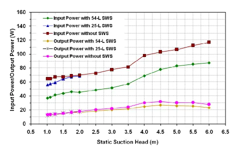
The ‘input power’ and ‘output power’ of the hand
pump without a secondary water sump and with 54 liters
and 25 liters metallic secondary water sumps are shown
below in Figure 4.
It is apparent from Figure 4 that the hand pump fitted
with a secondary water sump requires considerably less
input power compared to the hand pump without a
secondary water sump. It is also evident that larger the
capacity of secondary water sump, lesser is the force
requirement to operate the pump. However, the output
power in both the cases remains approximately same.
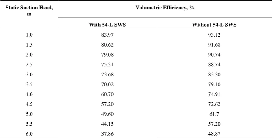
The volumetric efficiency of the hand pump with and
without 54 liters metallic secondary water sump varied
from 83.97 to 37.86% and 93.12 to 48.87%, respectively
for the static suction heads of 1.0 to 6.0 m (Table 3).
Further, the overall mechanical efficiency of the hand
pump with and without a randomly chosen 54 liters
metallic secondary water sump varied from 31.65 to
26.51% and 19.94 to 23.77%, respectively for the static
suction heads of 1.0 to 6.0 m (Figure 5). The maximum
mechanical efficiencies of the hand pump with and
without 54 liters metallic secondary water sump were
found to be 39.08% and 30.96% at the static suction
heads of 3 m and 4 m, respectively.
3.2 Effect of the capacities of secondary water sump
on the pump performance
The experiments on the hand pump with the randomly
chosen 25 liters GI and 54 liters MS secondary water
sumps revealed that a higher capacity secondary water
sump requires less operating force and hence, less input
power as compared to a smaller capacity secondary
water sump (Figure 4). However, the output power
remains more or less same for both types of secondary
water sumps. Therefore, the hand pump fitted with a
larger capacity secondary water sump appreciably
enhances the overall efficiency of the hand pump. Figure 5 Variation of overall efficiency with static suction heads of the hand pump without and with
randomly chosen 54-L and 25-L metallic secondary water sumps
Table 3 Volumetric efficiency of the hand pump with and without 54-L metallic secondary water sump (SWS) under different static suction heads
Static Suction Head, m
Volumetric Efficiency, %
With 54-L SWS Without 54-L SWS
1.0 83.97 93.12
1.5 80.62 91.68
2.0 79.08 90.74
2.5 75.31 88.74
3.0 73.68 83.30
3.5 70.02 79.10
4.0 60.70 74.91
4.5 57.20 72.62
5.0 49.60 61.7
5.5 44.15 57.20
4 Conclusions
Based on the performance evaluation of a hand pump
with and without sealed secondary water sumps, the
following conclusions are drawn:
(1) The experiments on a hand pump fitted with a sealed
secondary water sump revealed a significant
reduction in the input power to operate the pump.
(2) It was also found that the use of larger capacity
secondary water sump requires lesser operating
force to operate the pump or lesser input power than
the smaller capacity secondary water sump.
(3) The output powers in both the cases namely with and
without a secondary water sump are approximately
same.
(4) Overall, the provision of a secondary water sump for
a hand pump significantly increases its overall
efficiency and provides more comfort in operating
the hand pump.
Acknowledgements
The authors are very thankful to the erstwhile Head,
Department of Agricultural & Food Engineering, Indian
Institute of Technology (IIT) Kharagpur, West Bengal,
India for providing financial support and other facilitates
for carrying out this research.
References
Ajay Industrial Corporation (AIC). 1961. Force and Lift Hand Pump.
India,http://www.ajayindustrial.com/play-and-pump.html# force (accessed on June 14, 2007).
AOV International (AOVI). 1982. Extra Deep Well Hand Pump,
India Mark II Deep Well Hand Pump and India Mark III
Deep Well Hand Pump. India,
http://www.aovinternational.com/hand-pumps.html (accessed on June 26, 2007).
Consallen Water Wells and Hand Pumps (CWWHP). 1983.
Consallen Hand Pump, U.K.,
http://www.consallen.com/handpumps/ (accessed on June 14, 2007).
EZI- Action (EZIA). 1991. Hand Pump Power Measure, Hamilton,
New Zealand,
http://www.nzpump.com/eziaction_hand_pumps (accessed on June 4, 2007).
Jansen Venneboer B.V. (JVBV). 1990. Volanta Flywheel Hand Pump. Jansen Venneboer B.V., The Netherlands, www.volanta.nl (accessed on July 24, 2007).
Lal, J. 1969. Hydraulic machines. Metropolitan Book Co. (Pvt.) Ltd., Delhi, India.
Lifewater Canada (LC). 1998. The Bush Hand Pump. Canada, http://www.lifewater.ca/drill_manual/Section_13.htm (accessed on June 14, 2007).
Michael, A.M., and S.D. Khepar. 1999. Water well and pump engineering. Tata McGraw-Hill Publishing Co. Ltd., New Delhi, India.
National Research Council of Canada (NRCC). 1988. Awassa Hand Pumps. Canada, http://members.shaw.ca (accessed on June 8, 2007).
Parry-Jones, S., R. Reed, and B. H. Skinner. 2001. Sustainable hand pump projects in Africa. A Literature Review, Water Engineering and Development Center (WEDC), Loughborough University, U.K.
S.K. Industries (SKI). 1961. Tara Direct Action Hand Pump. India, www.skipumps.com (accessed on June 18, 2007).
SWS Filtration Ltd. (SWSFL). 1982. Rower Pumps. U.K., http://ds.dial.pipex.com/swsfilt/rower/index.htm (accessed on July 24, 2007).
Technology Transfer Division (TTD). 1990. The Rope Pump.
Nicaragua, S.A.,
http://www.ropepump.com/images/TechnicalDrawings.pd f (accessed on July 22, 2007).
Water Aid (WA). 1981. Diaphragm Hand Pump and Non-piston pump. Water Aid-Water for Life, Technology Notes, U.K., http://www.wateraid.org/~/media/Publications/Handpump s.ashx (accessed on July 24, 2007).
Watsan Consult (WC). 1986. Afripump. The Netherlands, http://www.watsan.com/show_detail.php?key=19&sgrp=0 (accessed on June 20, 2007).