A Portable Electronic Transaction Device Based on Dual
Interface Smart Card
https://doi.org/10.3991/ijoe.v16i03.11639
Syifaul Fuada ()
Universitas Pendidikan Indonesia, Pendidikan, Indonesia [email protected]
Akhmad Alfaruq, Trio Adiono Institut Teknologi Bandung, Bandung, Indonesia
Abstract—In recent years, electronic money facilities are increasingly di-verse. It may replace conventional payments. The use of physical money can be diminished by utilizing digital money, which is realized by smartphone apps, bar codes, smart cards, and so on. The types of smart cards used also vary, and it can be divided into two methods, i.e., with contacts and without contact. In this work, we develop electronic transaction devices using dual interfaces: con-tact and concon-tactless smart cards. As computational processing, we employ the Raspberry Pi 3 Model 3. It has a high processing speed, large memory, and small size. Hence our system enables to compact in a portable box. The features offered on our transaction device are as follows: transaction menu, balance check menu, payment menu, and top up menu. Also, we provide a device trans-action connection to the printer. Therefore, proof of transtrans-actions can be printed out easily. The device developed also provides a touch panel display to display the transaction menu.
Keywords—Smart card, contactless and contact smart card, electronic transac-tion device
1
Introduction
The rapid development of information technology has a significant impact on hu-man lifestyles. In Indonesia, this progress provides various facilities, one of which is the payment mechanism. The use of electronic money can increasingly replace regular payments. Electronic money offers many features and eases to use for transactions. Indonesia government regulation also triggers on the demand for electronic money, ex. Payment transactions on the highway, public transportation, and toll road that are required to use smart card contact.
com-panies registered at Bank Indonesia (BI) [2]. This fact shows that there is an excellent opportunity for companies to open up participation and competition in electronic money-based businesses.
There are several payment methods support transactions using existing electronic money, including Debit cards, Credit cards, E-wallet, Smart card, and Wireless pay-ment. Based on the technology used, it can be divided into two types of electronic money, namely Chip-based and server-based. Chip-based electronic cash is realized with a non-touch mechanism card, which is then called as a “smart card”. Whereas, Server-based digital money (E-wallet) generally uses applications on smartphones as media transactions such as T-cash, Go-pay, i.Saku, Sakuku, LinkAja, DOKU, Dana, OVO, and so on. The e-Wallet has disadvantage, e.g. the digital money only applies to specific merchants. Their services only for partner merchants. So, if the transaction is not with their partner, we must use another payment method. Another drawback is it depends on the internet network.
Chip-based, server-based, or combination of both are the most widely used for electronic money transactions nowadays, especially in Indonesia. This condition en-courages researchers and application designers in developing electronic payment systems with high-flexibility, fast data processing, user friendly, and it has a good performance (high-reliability). The existence of smart cards has received special at-tention since the last two decades. This embedded chip card has been widely used for various access applications. Research on the use of smart cards as electronic transac-tions have been carried out in [3-4], they implemented at System-On-Chip Zynq-700. Furthermore, media access control for security has been conducted, as in [5-9]. In [10], the RFID-based smart cards for goods locator applications have also been im-plemented. RFID-based contactless card has been proposed in [11-14] as a medium for electronic money transactions. However, In Ref [11-14] have not been equipped with the following features: payment, balance check, and top-up on single board com-puters. In Indonesia, many people have become users of smart contact and contactless smart cards. Thus, its penetration as a payment medium will increase significantly for the coming years.
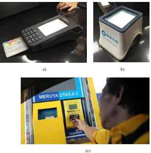
a) b)
(c)
Fig. 1. Commercial device of portable electronic transaction: (a) contactless; (b) contact smart card; (c) toll payment device that uses a contactless smartcard
Two payment methods, using contacts & contactless smart cards, are implemented on our system. It can be used to pay, refill (top-up) money, and check balances on minicomputers that are integrated with online database servers. Other features offered are Wi-Fi, print receipts, and payment list updates.
2
System Design
2.1 System Block
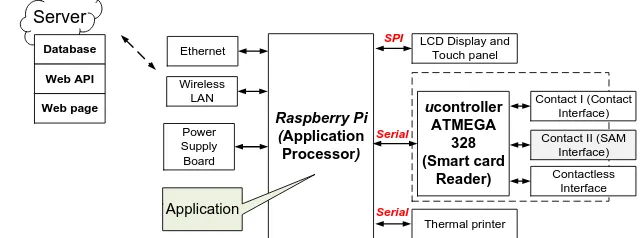
The whole system can be seen in Fig 2. It consists of three main parts, namely the hardware, software, and server. The system has specifications as follows:
It can perform balance check, top-up, and payment transactions
Contact, and contactless-type smart cards can access it
User interface using an LCD touchscreen
It can print the transaction proof by a thermal printer
The transaction history is recorded on the server. In this paper, we focus on point 1 to point 4. We will expand the content of this paper which covers point 5 in further publication. ucontroller ATMEGA 328 (Smart card Reader)
Contact I (Contact Interface)
Contact II (SAM Interface) Contactless Interface Raspberry Pi (Application Processor)
LCD Display and Touch panel Thermal printer Ethernet Wireless LAN SPI Serial Serial Power Supply Board Application Database Web API Web page Server
Fig. 2. Block diagram of a portable electronic transaction system
2.2 Operation procedure of smart card
The communication between reader to the Smart card need several procedures as shown in Fig. 3. Smart card contact has various types, an A-class smart card works at 4.5 to 5.5 V with 60 mA of maximum current. Then B-class and C-class operate at 2.7 to 3.3 V and 1.62 to 1.98 V with maximum current about 50 mA and 30 mA, respec-tively. At the first step, the smart card reader will determine the required operating voltage.
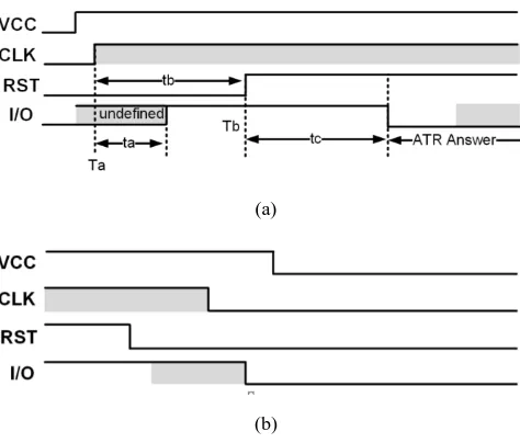
Further, the smart card will do following tasks: activate, cold reset, or warm reset. The operating voltage starts from the lowest to the highest voltage. This procedure must be done so the reader does not damage the card due to overvoltage. If the smart card supports that voltage class, it will respond “answer to reset” (ATR). While if the smart card does not send ATR, meaning that it does not support the used voltage class.
the clock pin is triggered by a clock signal starting at Ta point. The Cold reset can be done by keeping the reset pin at a low state on initial activation, about ~400 cycles (delay tb) which are calculated from the Ta point. Then the reset pin is set in a high state at Tb point. After that, the smart card will respond between 400 to 40,000 clock cycles. If the smart card does not answer within this period, the reader will deactivate it. The deactivation process starts by setting the reset pin in the low point, turning off the clock signal, and the last step is turning off the VCC. Due to the reset signal is in low state, the signal on the I/O pin will be ignored. The activation and deactivation process timing diagram can be seen in Fig. 4(a) and Fig. 4(b), respectively.
START
Apply a Class
Card answer to reset ? Answer is valid ?
Card indicates class ? Maintain current class? Yes
Yes
Yes
Continue normal operation
Yes No
Error handling No
End Yes
Deactivate
Select another class Take further action?
Yes
Delay
Abort No
Fig. 3. Procedure for class selection on a smart card
(a)
(b)
2.3 Data transmission on smart card
The data communication between the reader and smart card is serial in a bitstream form that is represented by high states and low states. While the voltage level used is corresponded the required voltage class, namely ± 5V, ± 3V, ± 1.8V with 0V as the reference voltage. In direct conventions, the high state is represented by a higher volt-age (± 5V or ± 3V or 1.8V), while 0V represents the low state. Whereas in reverse conventions do the opposite.
Elementary Data Unit (ETU) is the width for one bit of data. The ETU value is de-termined by the ratio of F per D multiplied by the clock cycle. F is the clock rate con-version integer, while D is the baud rate adjustment integer. Both F and D values can be obtained from information in ATR. At the beginning of communication, ETU values are determined as 372/f second, where f is in Hertz.
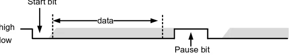
Character sending between a reader and a smart card contains 10 bits data, which can be high or low. Before the sending data process, the I/O pin condition must be in high state. The process starts with sending “start bits” as the first bit, which is low conditioned. Then proceed with sending 8 bits data (the second bit to ninth bit), the last is the parity bit (10 bits). The parity value for each bit must be not odd (even), which means if the number of bits 1 in the data is odd, then the parity value is 1. And if the number of bits 1 in the data is even, the parity value is 0. After sending the tenth bit, the I/O pin will remain in high state for 2 ETU before being ready to send the next character. The character frame format is illustrated in Fig. 5.
data Start bit
Pause bit high
low
Fig. 5. Data frame character of communication between the smart card reader and smart card
2.4 Hardware design
V +
Serial Ground
Raspberry Pi
Serial SPI
Power Supply Board
Smart Card Reader Module (Microcontroller, contact smart card slot)
Thermal Printer LCD Display
and Touch Panel
Fig. 6. Hardware design of electronic transaction devices based on contact and contactless smart card
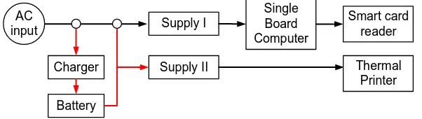
Power supply board, as shown in Fig. 7 was designed to provide a safe power sup-ply for all circuits. There are three loads in the reader device that must be powered properly: SBC, smart card reader, and printer. However, the power supply for the printer is developed separately because its input voltage varies, ranging from 5V to 12V with a relatively high current requirement. Moreover, we also provide battery backup in our board.
Supply I AC
input
Charger
Battery
Supply II
Single Board Computer
Smart card reader
Thermal Printer
Fig. 7. Block diagram of power board
2.5 Application design
The application has functioned as a graphical user interface. It was used to control the components in the reader device. Thus, it can work correctly, as expected. Con-trolled components include a smart card reader, LCD display, and printer. The appli-cation also handles input received through the touch panel. To be easy to operate the application, a menu layout and good input handlers need to be realized.
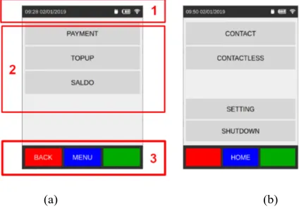
The layout on the LCD screen as visualized in Fig. 8(a), was divided into three sec-tions, namely:
Toolbar
Body
Navigation
The toolbar section contains hours & dates, the status of the charger, battery, and wireless LAN connection while the body section includes menus that will be dis-played by LCD screen and then operated (selected) by the users. Three transaction menus will be displayed, namely, balance check, payment, and top-up menus. Besides three transaction menus, as mentioned before, a configuration menu is also involved (Fig. 8b) in managing wireless LAN, printer, and partner list. Application must be able to access console on Linux. In this work, we used Qt library to develop applica-tions.
Qt is a free and open-source widget toolkit to develop GUI that run on various op-erating systems or embedded systems. By using Qt, special libraries also can be creat-ed, ex. interface library to a charger, Wi-Fi network, thermal printer, smart card read-er, and ADC reader feature. The charger library uses for interfacing the reader device to the charger board. Thus, the inputted power to the smart card reader device can be detected correctly. Considering this condition, we need two GPIO pins (for input and output) taken from the 40 pins GPIO extended on the Raspberry Pi.
(a) (b)
START
Start timer
Timer timeout?
Yes
End Yes Read GPIO input
GPIO input = 1?
Send signal charger on
Send signal charger off No
No
Yes No
(a) (b)
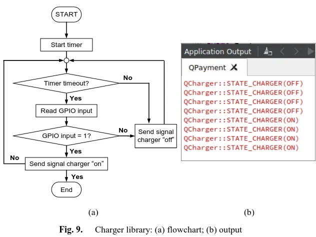
Fig. 9. Charger library: (a) flowchart; (b) output
The two GPIO pins are then connected to a relay that already connected to the charger line. If the charger is “on” position, the GPIO input & output is connected so that the input pin will be read as state high. It indicates that the charger is on. If the charger is “off” position, the relay disconnects the connection between the GPIO input & output, so the input reads state low. In this library, a timer is created to check the result every three seconds and send it, in the form of Signals & Slots, which is a communication mechanism in Qt. To test this library, we used a debug function found in Qt in which the workflow is depicted in Fig. 9(a). Based on the test results, as shown in Fig. 9(b), the library has appropriately functioned as expected. When the charger is turned off, the state becomes off and vice versa.
The network library was used for substituting the wireless LAN configuration on the reader device. The developed application requires an access to the Linux console, this configuration is done using the command on Linux console, wpa_cli -i wlan0 reconfigure. Before calling the command reconfigure, we need to create a file wpa_supplicant.conf which contains the name SSID and key. Before the file is creat-ed, turn off the network with the ifconfig wlan0 down command, then turn it “on” again with the ifconfig wlan0 up command.
3
Results and Analysis
3.1 Implementation
A photograph of portable electronic transaction device is visualized in Fig. 10. It has a weight of 128.58 gram, and L x W x H of 161 cm x 85 cm x 62 cm, respective-ly. The casing of portable transaction device is implemented using 3-Dimension print-ing with Polylactic Acid (PLA) material.
(a) (b)
(c) (d)
Fig. 10. The appearance of a portable electronic transaction device: (a) complete system [16]; (b) top view; (c) bottom view; (d) device dimension
3.2 Smart card operating procedure
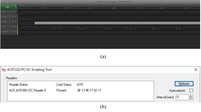
After the hardware and firmware are realized, the next step is to evaluate the smart card reader. First, we test it using contact smart card type. The Answer to Reset (ATR) data will start sending after the smart card reader has activated and cold reset. Fig 11(a) is the signal reading results from the logic analyzer for contact I interface.
Smart card Contactless
Smart card Contact
Charger
(a)
(b)
Fig. 11.The ATR signal received by the smart card reader: (a) on contact interface; (b) using ACR39U reader; (c) on SAM interface
From these signals as in Fig. 10(a) are then converted to bit streams (1 and 0 logics). By using the ETU calculation formula, we obtain clock cycles as follow: 1ETU 372 clock cycles. The conversion results are then separated
be-tween start bit, data, CRC, and pause bits. Thus, the actual data is obtained. Further, the obtained data are then converted to hexadecimal, so that the ATR value obtained is 3B 13 96 17 02 17, as shown in Fig. 11(b). To validate these results, the smart card is tested on the ACR39U reader. The SAM interface (contact II) test also using the same method, the logic analyzer test of SAM interface can be seen in Fig. 11(c) that is similar to the simulation result on contact I. Based on the test results, it was found that the reading of the ATR value on contact I and contact II interface was correct.
(b)
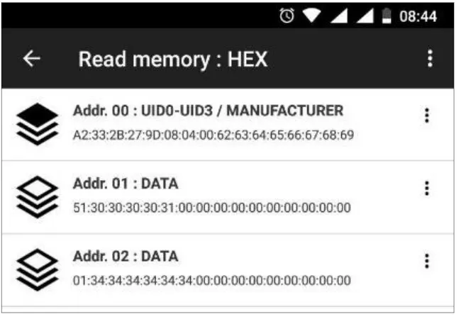
Fig. 12.The results of: (a) writing data and (b) reading data on contactless type smart cards using the proposed smart card reader
Later, we evaluate the read and write mechanism of contactless-type smart cards. The procedure used is the same as the contact type smart card test, which is writing data to the smart card (shown in Fig. 12a) and then reading it and comparing the results. In this test, the written data is stored in sector I. The test result of the reading mechanism on contactless smart cards can be seen in Fig. 12(b). To prove it, we test reading smart card by using a cellular telephone with an android OS that supports NFC. We use a specific application provided by NFC Tools. The reading results using NFC Tools can be seen in Fig. 12, it shows that the data sector 1 at the initial 6 bytes is 51 30 30 30 30 31, which is similar to results depicted in Fig. 12(a) and Fig. 12(b), i.e., 51 30 30 30 30 31. It proves that the smart card reader on contactless-type is functioning correctly.
3.3 Functional testing
The balance check menu is used to display the nominal balance on contact and contactless smart cards. The flow chart of the balance check process can be seen in Fig. 14. To make it easier to operate, we added several guide menus, as shown in Fig. 15(a) and Fig. 15(b) for contact and contactless type of smart cards, respectively.
The first step to check balances is to open the main menu, then select the smart card types. If the type of smart card is contact, put it in the provided slot. If the con-tactless smart card type, then attaches/tap it at the provided spot. If the smart card is successfully read, the balance will be displayed on the LCD screen as visualized in Fig. 15(c).
Users can select the payment menu to make payments using a smart card. The first step in the payment process is to open the main menu, then select the type of smart card used. This menu also displays a list of partners registered with the device. If the business partner is not yet recorded, we can make a payment by entering the partner ID manually. The complete payment process is illustrated in Fig. 16.
START
Main menu
Contactless type of
smart card?
Yes
End
Attach the smart card
Insert the
smart card
No
Display current balance
(a) (b) (c)
Fig. 15.The appearance of balance check menu on the card reader application: (a) a guide on contact smart card “please insert your card”; (b) a guide on contactless smart card
“please attach your card”; and (c) balance check result
After selecting a smart card type, the transaction menu will be displayed and then select the “payment” button. In this payment menu, a list of registered partners will be displayed on the screen, and there is one button provided to enter the ID partner man-ually. Partner ID is set uniquely to distinguish between one partner to other partners. After selecting partners or entering ID manually as visualized in Fig. 17(a), next step is to enter the paid cost, then press the OK button. After that, the confirmation menu will display the total cost and the partner name. This menu is used to check whether the information entered is correct or not. If so, press the OK button.
START
Main menu
Contact type of smart card?
No
Set the contactless card parameter Yes Set the contact card parameter Display the Transaction menu Select Payment menu Display the Payment menu Registered ID partner? Select Payment menu Yes Enter ID partner Enter amount of payment No Payment confirmation Contact type of
smart card? Insert the
smart card Yes
Enter
password Attach the smart card No
Successful transaction?
Send transaction data to the server and print the transaction proof
Display successful info Display failed info
Yes
End No
Fig. 16.Payment flow diagram
(a) (b) (c)
Flowchart of top-up process is depicted in Fig. 18. Following are steps of the balance top-up: firstly, enter the main menu, then select the smart card type. After that, select the top-up transaction type to display the topup menu. In this menu, a button which contains the nominal contents is displayed, i.e., 5K, 10K, 25K, 50K, 100K Rupiahs as visualized in Fig. 19(a). The user can choose the desired balance or refill the balance with tokens. A token is a unique code created by a server to fill a balance. The token input menu will be displayed when the “token” button is pressed. If the entered token is valid, we will see a confirmation menu on the application as shown in Fig. 19(b). The next step is to press “YES” button. Then, insert the smart card in the provided slot. If the process is successful, the information menu will be displayed and successfully refilled, along with the current balance value. Also, the application will send transaction data to the server and print successful top-up proof as shown in Fig. 19(c).
START
Main menu
Contact type of smart card?
No
Set the contactless card parameter Yes Set the contact card parameter Display the Transaction menu
Select Top-up menu
Display the Top-up menu
Using a Token? Insert a
Token Yes
Select filling nominal in Rupiah
No
Top-up confirmation Contact type of
smart card? Insert the
smart card Yes
Attach the smart card No
Successful transaction?
Send transaction data to the server and print the transaction proof
Display successful info Display failed info
Yes
End No
(a) (b) (c)
Fig. 19. Top-up transaction result: (a) the appearance of successful top-up on application; (b) proof of top-up activity
4
Conclusion
A Portable transaction device with dual interfaces (contact and contactless smart card) has been successfully developed using Raspberry as an application processor, ATMega328 as a smart card reader, and touchscreen as a user interface. In addition, transaction application can perform following tasks: balance check, top-up, and pay-ment transaction. In this work, writing data on the smart card still uses the plain text. Therefore, it is still vulnerable to duplication. We do not compare our system’s per-formance and to the available (existing) device, but compared to other devices on the feature aspect, our system can be operated in dual-mode and also can be connected to the own servers. Therefore, we expect that the transaction activity can be more se-cured. In further research, we will extend this paper with other major performance metrics (major properties parameters). We will apply the encryption feature as well as SAM mechanism for security.
5
References
[1]Bank Indonesia, “Statistik Sistem Pembayaran,” [Online]. Available:
https://www.bi.go.id/id/statistik/sistem-pembayaran/uang-elektronik/contents/transaksi.aspx. [Accessed on January 11, 2019].
[2]Bank Indonesia, “Informasi Perizinan Penyelenggara dan Pendukung Jasa Sistem Pem-bayaran,” [Online]. Available:
https://www.bi.go.id/id/sistem-pembayaran/informasi-perizinan/uang-elektronik/penyelenggara-berizin/Pages/default.aspx. [Accessed on January
11, 2019]. https://doi.org/10.21609/jsi.v13i1.465
[4]A.C. Swastika and T Adiono, “Design and implementation of smart card interface device on Zynq-7000 system-on-chip,” Proc. of ICITEE, July 2018. https://doi.org/10.1109/ici teed.2018.8534777
[5]P. Adole, J. M. Môm, and G.A. Igwue, “RFID Based Security Access Control System with GSM Technology,” Am. J. Eng. Res., Vol. 5(7), pp. 236–242, 2016.
[6]S. Thu, et al., “RFID-Based Monitoring and Access Control System for Parliamentary Campus,” Int. J. Sci. Technol. Res., Vol. 5(6), pp. 98–101, 2016.
[7]M. Sangole, et al., “RFID Based Campus Management System: Access Control System,” Int. J. Res. Eng. Appl. Manag., Vol. 3(2), 2017.
[8]G. Kaushal, et al., “RFID Based Security and Access Control System using Arduino with GSM Module,” Int. J. Eng. Technol., Vol. 2(2), pp. 309–314, 2015.
[9]U. Farooq, et al., “RFID Based Security and Access Control System,” Int. J. Eng. Tech-nol., Vol. 6(4), pp. 309–314, 2014.
[10]B. Yan, C. Yiyun, and M. Xiaosheng, “RFID technology applied in warehouse manage-ment system,” Proc. of ISECS Int. Colloq. Comput. Commun. Control. Manag., Vol. 3, pp. 363–367, 2008.
[11]V. Suryawanshi, et al., “Automatic Toll Collection System Using QR Code,” Int. J. Eng. Comput. Sci., Vol. 9(2), pp. 61–66, 2017.
[12]S. R. Zope and P. M. Limkar, “RFID based Bill Generation and Payment through Mobile,” Int. J. Comput. Sci. Netw., Vol. 1(3), pp. 2277–5420, 2012.
[13]S.-K. Noh, S.-R. Lee, and D. Y. Choi, “Proposed M-Payment System using Near-Field Communication and based on WSN-Enabled Location-Based Services for M-Commerce.,” Int. J. Distrib. Sens. Networks, Vol. 2014, pp. 1–8, 2014. https://doi.org/10.1155/2014/ 865172
[14]A. J. Najm, “Developing a Payment System Contactless Smart Card,” [Online]. Available: https://meu.edu.jo/libraryTheses/58734da8c19fa_1.pdf [Accessed on January 11, 2019]. [15]I.G. Purwanda, T. Adiono, S. Situmorang, F. Dawani, H.A. Samhany, and S. Fuada,
“Pro-totyping Design of Low-Cost Bike Sharing System for Smart City Application,” Proc. of IEEE Int. Conf. of ICT for Smart Society (ICISS), pp. 1-6, September 2017. https://doi. org/10.1109/ictss.2017.8288882
[16]T. Adiono, A. Alfaruq, and S. Fuada, “Hardware design of transaction device based on contact and contactless smart card,” Proc. of the IEEE Asia Pacific Conf. on Circuit and Systems (APCCAS), November 2019. https://doi.org/10.1109/apccas47518.2019.8953181
6
Authors
Paper Award from IEEE IGBSG 2018 that was held in Yi-Lan, Taiwan, receiving Best Paper Award from IEEE ICTRuDev 2018 that was held in Bali, Indonesia and receiving the Best paper award from a Scopus-indexed journal, i.e. International Jour-nal of Online Engineering (iJOE), and receiving Best Paper Award from IEEE IGBSG 2019 that was held in Yichang, China. He is a member of IAENG and an associate editor of Jurnal INFOTEL (p-ISSN: 2085-3688, e-ISSN: 2460-0997). His research interests include analog circuit design and instrumentation, circuit simula-tion, engineering educasimula-tion, IoT, multimedia learning development and Visible Light Communication.
Akhmad Alfaruq, received a B.Eng. in Electrical Engineering from Telkom Uni-versity, Indonesia, and he is with the M.Sc. in Electrical Engineering option Microe-lectronics from the School of Electrical Engineering and Informatics, Institut Teknologi Bandung (ITB), Indonesia. The author can be contact at alfaruq@ students.itb.ac.id. Jln. Ganesha No.10, Gd. Achmad Bakrie (LABTEK VIII) Lt. III, ITB campus, Bandung city 40132, West Java, Indonesia. Email: [email protected]
Trio Adiono received a B.Eng. in electrical engineering and an M.Eng. in microe-lectronics from Institut Teknologi Bandung, Indonesia, in 1994 and 1996, respective-ly. He obtained his Ph.D. in VLSI Design from the Tokyo Institute of Technology, Japan, in 2002. He holds a Japanese Patent on a High-Quality Video Compression System. He is now a Full professor and a senior lecturer at the School of Electrical Engineering and Informatics, and formerly serves as the Head of the Microelectronics Center, Institut Teknologi Bandung. His research interests include VLSI design, sig-nal and image processing, VLC, smart cards, and electronics solution design and inte-gration. [email protected]
![Fig. 10. The appearance of a portable electronic transaction device: (a) complete system [16]; (b) top view; (c) bottom view; (d) device dimension](https://thumb-us.123doks.com/thumbv2/123dok_us/554482.2054939/10.595.126.469.256.551/appearance-portable-electronic-transaction-device-complete-device-dimension.webp)