IJMF
Online ISSN: 2383-0042
Iranian Journal of Materials Forming
Journal Homepage: http://ijmf.shirazu.ac.ir
Simulation of a New Process Design to Fabricate a Rectangular Twist
Waveguide Using Extrusion and a Twist Die
M. Amiri∗ and R. Ebrahimi
Department of Materials Science and Engineering, School of Engineering, Shiraz University, Shiraz, Iran
A R T I C L E I N F O A B S T R A C T
Article history:
Received 22 August 2019 Revi sed 29 September 2019 Accepted 7 October 2019
The aim of the present study is to determine the feasibility of making a rectangular twist waveguide used to rotate electromagnetic waves. For this purpose, the process of fabricating an aluminum rectangular twist waveguide was simulated by making use of finite element method and Deform software. The optimum length and angle of the twist die for manufacturing a twist waveguide with inner cross sectional dimensions of 22.86 mm × 10.16 mm and a length of 50 mm and twisting angle of 90 degrees were investigated. Moreover, the effect of certain factors such as the length, thickness, cross section dimensions of the waveguide and friction on the optimum length of the twist die and cross sectional distortion was studied. The results of this study indicated that the length of the twist die had an influence on the amount of twisting, while friction was of no importance. In addition, comparing the values of effective stress and flow stress at the cross section of the workpiece behind the twist die depicted that the workpiece would not yield behind the twist die due to smaller values of effective stress.
© Shiraz University, Shiraz, Iran, 2019 Keywords:
Extrusion
Rectangular twist waveguide Simulation
Twist die
1. Introduction
Waveguides, common in electronic industries and radars, are transmission lines used to transport electromagnetic waves [1]. Waveguides have different types depending on the type of the transmitted wave; however, the main types are hollow profiles made of conductive metals such as aluminum, copper, brass and silver; which are used to carry waves in the microwave frequency range [1-3]. Wave transfer is carried out by the internal walls of the waveguide and the wave is reflected between the walls. The region within a waveguide is a dielectric medium which is usually air. The cross section of a waveguide is either rectangular or circular [1, 2]. The dimensions of rectangular waveguides are shown in the form of WR numbers which are the designations for waveguide rectangular [3].
∗ Corresponding author
E-mail address: [email protected](M. Amiri)
A WR number represents one hundred times of the length of the inner rectangle measured in inches. A twist waveguide is a type of waveguide used to rotate the electromagnetic field [4].
Extrusion as one of the metal forming processes is very effective in producing products with complex cross sections [5]. Therefore, it can be useful to produce rectangular waveguides. Extensive researches have been done on the extrusion process and its simulation in order to produce hollow profiles. Most of these studies are related to the modeling and analysis of the backward extrusion process [6, 7], piercing and extrusion [8-10] and porthole extrusion [11-18]. In the field of producing twisted sections using extrusion and a twist die, most researchers have produced helical sections and helical gears by means of a process named helical extrusion [19-22]. Khalifa and Tekkaya [23] have simulated a helical
IJMF
Iranian Journal of Materials Forming
Shiraz University O n line I S S N: 2383- 00 4 2
Published by: Shiraz University
Vo l. 6 N o. 2 October 2019
extrusion process to produce helical profiles used in screw rotors for compressors and pumps. For this purpose, they have used a hot extrusion process using a twisted die. They have observed that at an identical length of the twisted die and extruded specimen, the twisting angle of the extruded specimen is much less than that of the twisted die. Forward extrusion of hollow helical tubes has been simulated by Hwang and Chang [24] using Deform FEM software and the effects of bearing length, spiral angle, ram speed and initial billet temperature on the extrusion force and the filling ratio have been studied as well.
Up to the present, in order to fabricate twist waveguides, jigs and twisting machines have been used in industries [25].
In the present study, a novel process for manufacturing a rectangular twist waveguide is simulated using the finite element software, Deform 3D. No investigation has been done in the field of manufacturing twist waveguide till now to the best of the author’s knowledge, which utilizes the method proposed in the current research.
2. Materials and Methods
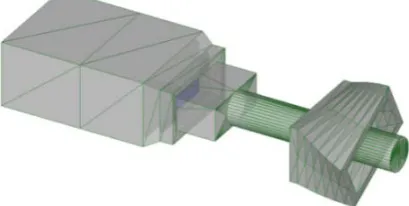
In the current model, an extrusion process is utilized prior to the twisting process in order to produce a preliminary profile, which is itself a waveguide. In this process, a hollow billet having a rectangular cross section is elongated during a forward extrusion process and its cross sectional dimensions decrease to the desired dimensions which are in accordance with the standard dimensions of rectangular waveguides. After the extrusion process, the workpiece enters a twist die and twists. The extrusion process is carried out by pushing a ram with a speed of 0.2 mm/s. A rectangular mandrel, which is designed to preserve the internal dimensions of the rectangle, is connected to the ram. In addition to the rectangular mandrel, a circular mandrel with a diameter equal to the internal width of the billet is designed so as to avoid the buckling of the workpiece during the twisting process. In addition, to prohibit the collision of the twist die and the rectangular mandrel, which is moving with the ram, the twist die is located at a proper distance from the extrusion die outlet.
The design of all geometries is performed by Solidworks software and the designed parts are imported to Deform software in order to model the twist
waveguide manufacturing process. In the simulation, the dies are assumed to be rigid and the billet to be plastic with an isotropic work hardening behavior. The billet is considered to be made of commercially pure aluminum which has a stress–strain relationship as σ =106ε0.347 (MPa) [26]. Fig. 1 shows the assembly of dies in the software.
Fig. 1. The assembly of dies in the simulation.
The billet is a rectangular cube with external dimensions of 28.86 mm × 16.16 mm and internal dimensions of 22.86 mm × 10.16 mm, and a height of 20 mm. After the extrusion process, the final product’s external dimensions will be reduced to 24.86 mm × 12.16 mm and the internal dimensions will remain unchanged. The cross sectional dimensions of 22.86 mm × 10.16 mm are the inside dimensions of WR90 [27]. The schematic diagram of the billet is represented in figure 2. The angle of the extrusion die is considered to be 25° during the process. Tetrahedral elements are used with the size of 0.3 mm to mesh the billet and the friction factor, m, is considered to be 0.1 in the extrusion process.
Fig. 2. The schematic diagram of the billet (all dimensions
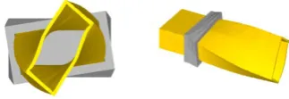
In order to reduce the simulation time to find the optimum length and angle of the twist die to achieve 90 degrees of twisting in the desired length of the workpiece, the extrusion process prior to the twisting process could be neglected and only the twisting process be simulated. The reason beyond this assumption is the ineffectiveness of the work hardening phenomenon on the amount of twisting which has been proved clearly in the next sections of this paper. Figure 3 illustrates the assembled model of the twisting process in the software.
Fig. 3. Assembled model of the twisting process.
In this case, the cross section of the workpiece is the same as the outlet dimensions of the extrusion die. The height of the workpiece shall be high enough so that the
desired length of the twist waveguide would pass completely through the twist die at the end of the simulation.
Based on the volume constancy law, the velocity of
the output material from the extrusion die would be 0.67 mm/s; therefore, the same data are considered as the speed of the input material, which is pushed to the twist
die by a ram. Moreover, a long rectangular mandrel is also designed to move within the workpiece at a speed of 0.2 mm/s, equal to the speed of the mandrel which is connected to the ram in the extrusion process. In order to reduce the amount of deviations from the real process,
by partitioning the mandrel, the parts of the mandrel which are longer than those of the real one are assumed to be frictionless. Similar to the previous part, a circular mandrel which is connected to the rectangular mandrel
is designed. The size of the elements in the simulation of the twisting process is assumed to be 0.5 mm.
In the current study, the aim is to make a WR90 twist
waveguide with a length of 50 mm. First, it is assumed that the amount of twist per unit length is linearly proportional to the length and angle of the twist die. The accuracy of the assumption is investigated by examining
the lengths and angles of 5 mm and 9°, 7.5 mm and 13.5°, 10 mm and 18°, 12.5 mm and 22.5°, 15 mm and
27°, 20 mm and 36°, 25 mm and 45° for the twist die. Therefore, the optimum length and angle of the twist die for manufacturing a WR90 waveguide with a length of
50 mm and twisting angle of 90 degrees are investigated. Furthermore, the influence of factors such as friction,
length, thickness and cross section dimensions of the waveguide on the optimum length of the twist die and cross section distortion are studied. The drawing of the twist die with a length and an angle of 20 mm and 36° is
illustrated in figure 4 as a sample.
Fig. 4. The drawing of the twist die with a length and an
angle of 20 mm and 36°, illustrated as a sample.
3. Results and Discussion
Figures 5 - 11 show the amount of twist for the WR90 waveguide with a length of 50 mm for the twist dies with lengths of 5 mm, 7.5 mm, 10 mm, 12.5 mm, 15 mm, 20 mm and 25 mm respectively.
Fig. 5. The amount of twist for the 50 mm WR90 waveguide
Fig. 6. The amount of twist for the 50 mm WR90 waveguide
by means of a 7.5 mm and 13.5° twist die, with an ultimate angle of twist of 75°.
Fig. 7. The amount of twist for the 50 mm WR90 waveguide
by means of a 10 mm and 18° twist die, with an ultimate angle of twist of 80°.
Fig. 8. The amount of twist for the 50 mm WR90 waveguide
by means of a 12.5 mm and 22.5° twist die, with an ultimate angle of twist of 83°.
Fig. 9. The amount of twist for the 50 mm WR90 waveguide
by means of a 15 mm and 27° twist die, with an ultimate angle of twist of 85°.
Fig. 10. The amount of twist for the 50 mm WR90 waveguide
by means of a 20 mm and 36° twist die, with an ultimate angle of twist of 90°.
Fig. 11. The amount of twist for the 50 mm WR90 waveguide
by means of a 25 mm and 45° twist die, with an ultimate angle of twist of 90°.
Figures 5 - 11 depict that by increasing the length and
angle of the twist die, the amount of twist gradually
increases up to 90 degrees. According to figure 10, in
order to achieve 90 degrees of twist, the minimum length
and angle of the twist die shall be 20 mm and 36°. In
larger lengths, there will be no change in the amount of
twist as it is illustrated in figure 11. Therefore, it is
important to obtain the optimum length and angle of the
twist die since in lengths less than the optimum one, the
desired angle of twisting would not be achieved and in
lengths more than the optimum value, the amount of the
required force to fulfill the process would become higher
due to the increase in friction force. Moreover, it could
be said that the fabrication of longer twist dies would be
more difficult and costlier.
Having a hollow cross section, the product will be
distorted during the twisting process and deviate from its
rectangular shape, refer to figures 5 to 11. In the studied
case, the short length and little thickness of the
waveguide in comparison to the cross section
dimensions intensified the distortion due to the increase
in strain. Definitely, by increasing the length and the
thickness of the waveguide, the distortion will be
reduced; however, it should be mentioned that there is a
limit for increasing the length of the produced
waveguides with this method due to the possibility of
buckling behind the twist die. The length and the angle
of 20 mm and 36° are the optimum length and angle of
the twist die only for a 50 mm WR90 waveguide and
the changes in the cross section dimensions and length
would alter the optimum length of the twist die
because of strain changes. In the next subsections, the
effect of length and cross sectional dimensions are
3. 1. Effect of length
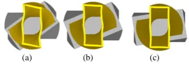
By simulating the twisting process for different lengths in a constant cross section, it is observed that the ratio of the twist die’s optimum length to the waveguide’s length would decrease by increasing the length of the waveguide. For example, as it was mentioned in section 3, for a WR90 having a thickness of 1 mm and length of 50 mm, a twist die with the minimum length of 20 mm is required to reach 90 degrees of twist, i.e. 2/5 of the waveguide’s length. However, by increasing the length of WR90 to 100 mm and 200 mm, the optimum length and angle of the twist die will be 25 mm and 22.5°, 1/4 of the waveguide’s length, and 20 mm and 9°, 1/10 of the waveguide’s length, respectively. Furthermore, the cross section distortion will be reduced due to reduction in strain. In figure 12, the amount of the observed distortion for the three waveguide lengths is shown. The optimum twist die for each length is considered in figure 12.
(a) (b) (c)
Fig. 12. The amount of the observed distortion in the WR90
cross section for lengths of: (a) 50 mm, (b) 100 mm, (c) 200 mm.
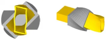
3. 2. Effect of cross section
By comparing the optimum length of the twist die for
two different cross sections in a constant length, it is
observed that the twisting process would become more
difficult by increasing the cross section dimensions due
to the enhancement in strain. So as for two cross sections
of 12.95 mm × 6.477 mm, WR51, and 22.86 mm × 10.16
mm, WR90, with a constant length of 100 mm and 1 mm
thickness, the optimum length and angle of the twist die
to achieve 90 degrees of twist will be 12.5 mm and
11.25°, 1/8 of the waveguide’s length, and 25 mm and
22.5°, 1/4 of the waveguide’s length, respectively.
Increasing cross section dimensions leads to the
enhancement of cross section distortion. Figure 13
depicts the obtained distortion in the above mentioned
cross sections.
(a) (b)
Fig. 13. The amount of observed distortion in 100 mm length
and cross section of: (a) 12.95 mm × 6.477 mm (WR51), (b) 22.86 mm × 10.16 mm (WR90).
3. 3. Effect of thickness
It is concluded from the simulation results that for the
twisting process of two WR90 waveguides with length
of 50 mm and different thicknesses of 1mm and 2 mm,
the twist die optimum length and angle would be equal
to 20 mm and 36° for both thickness values. Therefore,
it could be said that thickness has no significant effect
on the amount of twist. The only effect of thickness is on
the amount of cross section distortion. The amount of
distortion would decrease by increasing the thickness.
Figure 14 illustrates the distortion in the cross section
after the twisting process for the mentioned waveguides
by means of their optimum twist dies.
(a) (b)
Fig. 14. The amount of the observed distortion in the cross
section of a 50 mm WR90 and thickness of: (a) 1, (b) 2 mm.
3. 4. Effect of friction
In order to assess the influence of friction factor on the amount of twist, two different cases are studied. In
one case, the friction factor of m=0.1 is considered for the twisting process and in the other case, the whole twisting process is considered to be frictionless. It is
deduced from the simulation results that friction has no effect on the amount of twist. Figures 15 and 16 show the amount of twisting for two twist dies of 12.5 mm and 22.5° and 20 mm and 36°, respectively, for a 50 mm
(a) (b)
Fig. 15. The amount of twist for a WR 90 in length of 50 mm
by means of a 12.5 mm and 22.5° twist die in the frictional conditions of: (a) frictionless, (b) m=0.1.
(a) (b)
Fig. 16. The amount of twist for a WR 90 in length of 50 mm
by means of a 20 mm and 36° twist die in the frictional conditions of: (a) frictionless, (b) m=0.1.
3. 5. Effect of work hardening caused by the extrusion process
The amount of twist for the workpiece after twisting with the existence of an extrusion process prior to the twist die is shown in figures 17 and 18. As it can be deduced from these figures, the final results of twisting are identical with the case where there is no extrusion process prior to the twist die, refer to figures 8 and 10. Hence, it could be concluded that the
work hardening resulting from the extrusion process does not affect the amount of twist. Therefore, in order to accelerate the simulation process to optimize the twist die, the extrusion process can be omitted.
3. 6. Investigation of the workpiece yielding behind the twist die
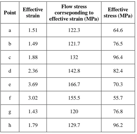
By substituting the effective strain in the Hollomon’s equation, the flow stress will be calculated at each strain. Workpiece yielding behind the twist die would not occur if the effective stress in the workpiece is less than the flow stress. In order to investigate this issue, during the simulation process utilizing an extrusion die, several points in the cross section of the workpiece behind the twist die were selected and the effective stress and the effective strain, and the corresponding flow stress in these points were obtained. The selected points and the distribution of the effective strain and effective stress are illustrated in figures 19 and 20. The results for these points are reported in Table 1. As can be seen in table 1, at any point the effective stress is less than the flow stress; therefore, yielding will not occur. Hence, it can be deduced that if manufacturing a twist die with high dimensional accuracy is feasible, the proposed method in this paper could be practical and industrialized.
(a) (b)
Fig.17. The amount of twisting for a 50 mm WR90 by means of a 12.5 mm and 22.5° twist die:
(a) with utilizing an extrusion die, with an ultimate angle of twist of 83° for the workpiece, (b) without utilizing an extrusion die, with an ultimate angle of twist of 83° for the workpiece.
(a) (b)
Fig. 18. The amount of twisting for a 50 mm WR90 by means of a 20 mm and 36° twist die:
Fig. 19. The distribution of the effective strain in the cross section of the workpiece behind the twist die.
Fig. 20. The distribution of the effective stress in the cross
section of the workpiece behind the twist die.
Table 1.The values of the effective strain and effective stress and the flow stress for the selected points in the cross section
behind the twist die
Point Effective
strain
Flow stress corrseponding to effective strain (MPa)
Effective stress (MPa)
a 1.51 122.3 64.6
b 1.49 121.7 76.5
c 1.88 132 96.4
d 2.36 142.8 82.4
e 3.69 166.7 70.3
f 3.02 155.5 55.7
g 1.43 120 76.8
h 1.79 129.7 96.2
4. Conclusion
In the current study, an innovative method for fabricating an aluminum rectangular twist waveguide was modeled. The obtained results are summarized as follow:
1 - Simulating results unveiled the fact that there would be an optimum length for the twist die. Hence, in the length values shorter than the optimum one, the desirable twisting angle for the waveguide would not be achieved.
2 - The results illustrated that increasing the length of the waveguide in a constant cross section or reducing the cross sectional dimensions in a constant length would lead to an easier twisting process due to strain reduction. Furthermore, the ratio of the optimum length of the twist die to the length of the waveguide would be reduced in these two cases. Also, the amount of distortion occurring in the cross section would be decreased.
3 - It was observed from the results that the waveguide thickness would not affect the optimum length and angle of the twist die. The effect of the thickness would be only on the amount of distortion in the cross section, in a way that a decrease in the thickness causes the distortion to increase.
4 - Simulation of the twisting process under two circumstances which were considered so as to evaluate the influence of friction, i.e. frictionless case and the case having friction factor of m=0.1, revealed the friction factor would have no effect on the amount of twisting.
5 - It was deduced that the values of the effective stress behind the twist die, which were less than the values of the flow stress would not cause the workpiece to yield behind the twist die, which shows the proposed fabricating method is reasonably feasible.
6 - By investigating the effect of work hardening, resulting from the extrusion process prior to the twisting process, it could be concluded that work hardening has no effect on the amount of twisting.
Acknowledgements
The authors appreciate Shiraz University for
financial support (grant number 96-GR-ENG-15) and
5. References
[1] U. A. Bakshi, A. V. Bakshi, Transmission Lines and
Waveguides, Technical Publications, Pune (2009),
Chapter 1, pp. 1-2.
[2] V. S. Bagad, Microwaves and Radar, Technical
Publications, Pune (2008), Chapter 2, pp. 1-2.
[3] M. Sharififar, S. A. A. Akbari Mousavi, Simulation and
optimization of hot extrusion process to produce
rectangular waveguides, The International Journal of
Advanced Manufacturing Technology 79 (2015)
1961-1973.
[4] A. S. Khan, Microwave Engineering: Concepts and
Fundamentals, CRC Press, Boca Raton (2014), pp.
170-171.
[5] G. E. Dieter, D. J. Bacon, Mechanical Metallurgy,
McGraw-Hill, New York (1986) 616-617.
[6] M. M. Moshksar, R. Ebrahimi, An analytical approach
for backward-extrusion forging of regular polygonal
hollow components, International journal of
mechanical sciences 40 (1998) 1247-1263.
[7] S. H. Kim, S. W. Chung, S. Padmanaban, Investigation
of lubrication effect on the backward extrusion of
thin-walled rectangular aluminum case with large aspect
ratio, Journal of Materials Processing Technology 180
(2006) 185-192.
[8] N. R. Chitkara, A. Aleem, Axi-symmetric tube
extrusion/piercing using die–mandrel combinations:
some experiments and a generalised upper bound
analysis, International journal of mechanical sciences
43 (2001) 1685-1709.
[9] S. Hansson, Simulation of Stainless Steel Tube
Extrusion, Doctoral dissertation, Luleå University of
Technology, Sweden (2006).
[10] L. De Pari, W. Z. Misiolek, Numerical modeling of
copper tube extrusion: Process and eccentricity analysis,
Journal of Manufacturing Science and Engineering 134
(2012) 051005.
[11] J. Lof, Y. Blokhuis, FEM simulations of the extrusion
of complex thin-walled aluminium sections, Journal of
Materials Processing Technology 122 (2002) 344-354.
[12] J. M. Lee, B. M. Kim, C. G. Kang, Effects of chamber
shapes of porthole die on elastic deformation and
extrusion process in condenser tube extrusion, Materials
& Design 26 (2005) 327-336.
[13] H. H. Jo, S. K. Lee, C. S. Jung, B. M. Kim, A non-steady
state FE analysis of Al tubes hot extrusion by a porthole
die, Journal of Materials Processing Technology 173
(2006) 223-231.
[14] W. Xianghong, Z. Guoqun, L. Yiguo, M. Xinwu,
Numerical simulation and die structure optimization of
an aluminum rectangular hollow pipe extrusion process,
Materials Science and Engineering: A 435–436 (2006)
266-274.
[15] G. Liu, J. Zhou, J. Duszczyk, FE analysis of metal flow
and weld seam formation in a porthole die during the
extrusion of a magnesium alloy into a square tube and
the effect of ram speed on weld strength, Journal of
Materials Processing Technology 200 (2008) 185-198.
[16] L. Li, H. Zhang, J. Zhou, J. Duszczyk, G. Y. Li, Z. H.
Zhong, Numerical and experimental study on the
extrusion through a porthole die to produce a hollow
magnesium profile with longitudinal weld seams,
Materials & Design 29 (2008) 1190-1198.
[17] C. Zhang, G. Zhao, Z. Chen, H. Chen, F. Kou, Effect of
extrusion stem speed on extrusion process for a hollow
aluminum profile, Materials Science and Engineering:
B 177 (2012) 1691-1697.
[18] C. Zhang, G. Zhao, H. Chen, Y. Guan, F. Kou,
Numerical simulation and metal flow analysis of hot
extrusion process for a complex hollow aluminum
profile, The International Journal of Advanced
Manufacturing Technology 60 (2012) 101-110.
[19] D. Y. Yang, T. Altan, Analytical and experimental
investigation into lubricated three-dimensional
extrusion of general helical sections, CIRP Annals -
Manufacturing Technology 35 (1986) 169-172.
[20] D. Y. Yang, K. Lange, Investigation into
non-steady-state three-dimensional extrusion of a trocoidal helical
gear by the rigid-plastic finite element method, CIRP
Annals - Manufacturing Technology 43 (1994) 229-233.
[21] Y. B. Park, J. H. Yoon, D. Y. Yang, Finite element
analysis of steady-state three-dimensional helical
extrusion of twisted sections using recurrent boundary
conditions, International Journal of Mechanical
Sciences 36 (1994) 137-148.
[22] H. Yoshida, Y. Sawaki, Y. Sakaida, Shaping of helical
gear by two-step cold extrusion, Materials transactions
[23] N. B. Khalifa, A. E. Tekkaya, Newest developments on
the manufacture of helical profiles by hot extrusion,
Journal of Manufacturing Science and Engineering 133
(2011) 061010-061010.
[24] Y. M. Hwang, C. N. Chang, Hot extrusion of hollow
helical tubes of magnesium alloys, Procedia
Engineering 81 (2014) 2249-2254.
[25] Military Standardization Handbook, Fabrication of
Rigid Waveguide Assemblies (Sweep Bends and
Twists), Military Specification of the Department of
Defense of the United States of America (2012).
[26] N. Pardis, R. Ebrahimi, Deformation behavior in
Simple Shear Extrusion (SSE) as a new severe plastic
deformation technique, Materials Science and
Engineering: A 527 (2009) 355-360.
[27] P. Eskelinen, Introduction to RF Equipment and
System Design, Artech House, Norwood (2004), pp.