JNS 2 (2012) 301-311
Numerical Simulation of Mixed Convection Flows in a Square
Double Lid-Driven Cavity Partially Heated Using Nanofluid
A. A. Abbasian Arania,*, J. Amania, M. Hemmat Esfeha
a
Mechanical Engineering Department, University of Kashan, Kashan, I.R. Iran
Abstract
A numerical study has been done through an Al2O3–water in a double
lid-driven square cavity with various inclination angles and discrete heat sources. The top and right moving walls are at low temperature.
Half of the left and bottom walls are insulated and the temperatures
of the other half are kept at high. A large number of simulations for a wide range of Richardson number of 0.1 to 10, Reynolds number
from 1 to 100, inclination angle of cavity from -90o to 90o and solid volume fraction between 0 and 0.06 are performed. The results are
presented in the form of streamline, isotherm and Nusselt number
plots. The influence of solid volume fraction of nanofluids and angle
of inclination on hydrodynamic and thermal characteristics have been analyzed and discussed. As a result, it was found that the heat
transfer increases with increase in solid volume fraction for a constant Reynolds number, heat transfer also increases with increase
in Richardson and Reynolds for a particular volume fraction.
2012 JNS All rights reserved
Article history:
Received 21/8/2012 Accepted 19/11/2012 Published online 1/12/2012
Keywords:
Non-uniform wall temperature Partially heated
Double lid-driven cavity Mixed convection
*Corresponding author:
E-mail address:
abbasian@kashanu.ac.ir Phone: 98 361 5912413 Fax: +98 361 5912475
1. Introduction
Fluid flow and heat transfer in a cavity which is
driven by buoyancy and shear force are encountered in a variety of thermal engineering applications [1–
3]. Interaction of buoyancy force due to temperature
gradient and forced convection due to shear forces is a complex phenomenon in mixed convection flow
and heat transfer. Numerous research on this type of
problem including the single or double lid-driven cavity flow and heat transfer involving different
cavity configurations, various fluids and imposed
temperature gradients have been published in the last
two decade. For example, Sharif [4] conducted a study for laminar mixed convection in shallow
inclined driven cavities with hot moving lid on top and cooled from bottom and concluded that the
average Nusselt number increases with cavity
inclination angle for forced convection-dominated
302
A.A.Abbasian Arani et al./ JNS 2 (2012) 301-311
(Ri=10). Kandaswamy et al. [5] conducted a
numerical study on buoyancy-driven convection in a
cavity with partially thermally active vertical walls.
They showed that heat transfer rate is increased when the heating location is at middle of the hot wall.
Ghasemi and Aminossadati [6] made a numerical study on mixed convection in a partially heated
square cavity. In this study, they kept the right wall
at low temperature and move vertically either a
constant velocity or with a sinusoidal oscillation. The results indicated that the direction and magnitude of
the sliding wall velocity affect the heat transfer rate. In most of the studies found in the literature, vertical
walls are considered to be isothermal in mixed
convection flow and heat transfer in cavity.
However, in many engineering applications, angle of cavity and the heater and cooler play an important
role in the fluid flow and heat transfer, particularly for electronic equipment cooling. In order to
understand the effect of cavity inclination and heater
size and locations on mixed convection, in the present study we examine the heat transfer and fluid
flow for a different model of this type of problem in
a lid-driven cavity.
In addition, all of cited above studies were done for
a pure base fluid without nanoparticles. Nanofluids
are a new class of fluid consist a suspension of nanometer-sized particles (below than 100 nm) in a
base fluid such as water, ethylene glycol or
propylene glycol. Use of high thermal conductivity metallic nanoparticles increases the thermal
conductivity of such mixtures [7]. Nanofluid caused
an enhancement in thermal performance and a motivation for generation and using this new heat
transfer fluid in building heating, in heat exchangers,
in plants and in automotive cooling applications.
Therefore in two last two decade, nanofluids have attracted more attention for using as coolant
(working fluid) in various industrial applications. For
instance just 0.3% volume fraction of copper
nanoparticles with 10 nm diameter led to an increase
of up to 40% in the thermal conductivity of ethylene
glycol [8].
By a literature survey one can found that a few
studies have been done on mixed convection in a lid-driven cavity for a nanofluid. Muthtamilselvan et al.
[9] studied the heat transfer enhancement of
copper-water nanofluids in a lid-driven enclosure with
different aspect ratios and solid volume fraction. They confirmed that the addition of Cu nanoparticles
into pure water increased the thermal performance of the cavity. Recently Abbasian Arani et al. [10]
present a numerical study on mixed convection in a
cavity. They conducted an investigation on the
effects of Richardson number, phase deviation of sinusoidal heating, and volume fraction of
nanoparticles on flow and temperature field.
It must be pointed that the heat transfer enhancement
by using of nanofluids is still a controversial issue.
Ho et al. [11] and Abu-Nada [12] argued that the augmentation or mitigation of heat transfer reported
in the published numerical studies is due to the
variation in the models used to predict the properties of nanofluids. Thus, further Computational Fluid
Dynamics (CFD) studies need to take account of
more accurate modeling of nanofluid properties. This study deals with the mixed convection heating
of nanofluid in a square enclosure where the bottom
and left walls are heated non-uniformly, right and top walls are cooled and pulled with a uniform velocity.
These boundary conditions are typical
representations of heating of fluid in a container where heat treatment is applied at the bottom and the
side wall would correspond to non-uniform heating
rate such that the heating rate is zero at a portion of
the bottom and left walls. The cold side wall often appears in presence of cold outer environment and
303
A.A.Abbasian Arani et al./ JNS 2 (2012) 301-311
thermal gradient. Convection patterns in such
situation may be interesting and the studies on mixed
convection with such boundary conditions are not yet
reported till date. The aim of the present investigation is to provide a complete understanding
about the physical insight of the problem, solution procedure using finite volume method and detailed
analysis of temperature and the flow fields on heat
transfer evaluation.
2. Mathematical Model
The schematic diagram of current study is
displayed in Fig. 1.
Fig. 1 Schematic diagram of the physical system.
It basically consists of a double-lid driven square
cavity with side L filled with Al2O3-water nanofluid
where the shape and size of solid particles are assumed to be uniform. It assumes that the nanofluid
in the cavity is Newtonian, incompressible and
laminar. The half of left and bottom walls maintain at high temperature, Th. The top and right walls of the
cavity are assumed to move in its own plane with a constant velocity, U0, and at low temperature, Tc, that
Tc is lower than Th. Other portions of walls are
adiabatic.
With this configuration and boundary conditions, the
present investigation has done for the cavities at
inclination angles range from -90o to 90o, Richardson
number from 0.1 to 10 and Reynolds number between 1 and 100. The impact of mentioned above
parameters on the streamline, isotherms and the average Nusselt number is discussed. It is assumed
that the Boussinesq approximation is valid for body
force term. Thermophysical properties of base fluid
and particles are given in table 1.
Table 1. Thermophysical properties of base fluid and nanoparticles [8].
Physical Properties Fluid (Water) Solid (Al2O3)
Cp(J/kg K) 4179 765
ρ (kg/m3) 997.1 3970
K (W m-1 K-1) 0.6 25
β×10-5 (1/K) 21. 0.85
μ×10-4(Kg/m s) 8.9 ……..
The governing equations are mass, momentum and
energy. These equations are converted to
non-dimensional form by using the non-non-dimensional
variable that normally used in this type of problem. For density, thermal capacity and thermal expansion
of nanofluid general relation for mixture are used. Thermal diffusivity, viscosity and conductivity of
nanofluid are expressed as bellow:
2.5
,
( ) (1 )
nf f
nf nf
p nf
k c
(1)
2 2 ( )
2 ( )
nf s f f s
f s f f s
k k k k k
k k k k k
(2)
The viscosity of the nanofluid expressed by the Brinkman [13] and the effective thermal conductivity
of the nanofluid approximated by the Maxwell–
Garnetts model [14].
The dimensionless forms of governing equations
304
A.A.Abbasian Arani et al./ JNS 2 (2012) 301-311
0
U V
X Y
(3)
2
1
. . sin
Re Pr
nf nf
f f
U U P Ri
U V U
X Y X
(4)
2
1
. . cos
Re Pr
nf nf
f f
V V P Ri
U V V
X Y Y
(5)
2 nf f U V X Y
(6)
In order to investigation the heat transfer
enhancement, the local Nusselt number defined as Eq. (7): f hL Nu k (7) The average Nusselt number are calculated over the hot surfaces by Eq. (8) by assuming a continuum
surface of two heat source surfaces. Each heat source
length is equals to L/2. The total hot surface length is L. The parameter ‘l’ indicates the differential length
in direction of heat source surface.
0
1 L
m
Nu Nudl L
(8)The boundary conditions are in the following forms:
0
0, Right wall:
0
U V U
(9) 1 2 1 0 2
0, 0
1, 0 Left wall:
0, 1 x X U V Y Y (10) 1 2 1 0 2
0, 0
Bottom wall: 1, 0
0, 1
Y Y U V X X (11)
0, 0 Top wall:
0
U U V
(12)
3. Numerical method
Numerical solutions to the governing equations
carry out by use the finite volume computational procedure and the SIMPLE algorithm as given in
Patankar [15]. The present numerical solution was
validated by comparing the present code results and
results of Basak et al. [1].
There is accordance between diagrams according to
Fig. 2.
Fig. 2. Local Nusselt numbers for current study (-▪-▪-) and Basak (….) [1].
Numerical code was tested for grid independence by calculating the average Nusselt number on the
heat source surface according to table 2 for two different cases. It was found that a grid size of
151×151 ensures a grid independent solution in
uniform mesh.
Table 2. Mesh finding.
Average Nusselt Number and ψmax for
Grid
γ =0o,φ=0.06,
Re=10, Ri=5
γ =60o, φ =0.0,
Re=100, Ri=1
m
Nu ψmax
m
Nu ψmax
25×25 3.2272 0.1788 5.8607 0.1621
41×41 3.3178 0.1763 5.8558 0.1609
65×65 3.3798 0.1747 5.8929 0.1605
91×91 3.4037 0.1742 5.9340 0.1604
111×111 3.4180 0.1739 5.9553 0.1603
133×133 3.4283 0.1737 5.9724 0.1603
151×151 3.4363 0.1736 5.9827 0.1603
171×171 3.4395 0.1736 5.9859 0.1603
191×191 3.4405 0.1736 5.9871 0.1603
Distance, X L o c a l N u s s e lt N u m b e r, N u b
0.2 0.4 0.6 0.8
305
A.A.Abbasian Arani et al./ JNS 2 (2012) 301-311
4. Results and discussion
Investigations through the cavity are made for the
ranges of the Richardson number from 0.1 to 10.
Reynolds number and nanoparticle concentration varies between 1 to 100 and 0.0 to 0.06 respectively.
Cavity angle has a value of range -90 to 90 degree.
Figs. 3-8 represent the isotherms and streamlines for Richardson equal to 3 and nanoparticles
concentration between 0.0 and 0.06. In all cases, with
increasing Reynolds number, intensity of the streamlines and temperatures near hot walls increases
and stronger circulation appears in the cavity. So the
flow rate near surfaces increases and consequently the total heat transfer increases. Different behavior is
observed by change of the Reynolds number.
Buoyancy force at γ=-90o (Fig. 3) is minimum and
movement of hot flow due to buoyancy force is in
the same direction so that only a clockwise circulation is generated in the cavity. Only one
circulation is observed in the cavity with the
increasing of γ to 30o (Fig. 3 and 4) because
buoyancy and shear forces are in same direction. At
γ=30o to γ=90o, Fig. 4 and 5, buoyancy force
generates a counterclockwise circulation.
Since the movement of the walls generates CW circulation in the cavity, at high Reynolds numbers
in which two above-mentioned forces become
important, two circulations are generated in the cavity. The strength and the dimension of
circulations near the hot walls increase by
enhancement of γ or Reynolds number. The
buoyancy forces at γ=0o and γ=90o are the same but
shear force opposes buoyancy force in γ=90o. Thus
Numfor γ=0
o
is more than γ=90o.
By increasing of γ from -90o to -30o, Fig. 3, the
streamlines become more intensified near the
surfaces. An opposite behavior is observed at γ =0, 30 and 60 degrees, Fig. 4. Temperature lines change
for γ =90o, Fig. 8, at high Reynolds number because
of the formation of two circulations in the cavity.
In Fig. 7 it is clearly observed that intensity of
temperature lines for γ =90o is higher than γ =60o. Buoyancy force increases by enhancement of angle
from -90o to -30o. At these angles, buoyancy and shear forces are in the same direction. Thus it is
expected that Num increases by increasing of γ from
-90o to -30o.
The bottom surface of heat source has more effect on heat transfer at γ =-30o relative to γ =0o. Also,
upward movement of hot flows due to buoyancy force affects the temperature lines and streamlines
near the left heat source (vertical wall), Fig. 6 and 7.
Thus Num for γ =-30 o
is more than Num for γ =0 o
. As
mentioned, the average Nusselt number decreases for angles from 0o to 60o. The dimension of circulation
increases for γ =90o, Fig. 5, due to clash of two moving flows created by heat transfer and lids wall.
This circulation covers about half of the cavity. So
for γ =90o, Num is more than that of γ =60 o
in Ri=7 and 10. At Ri=3 and 0.1, Num decreases by
increasing of angles because the contribution made
by the natural heat transfer is lower than force convection.
In all angles with increasing of Richardson
number, Fig. 9 the contribution of forced convection to the buoyancy force reduces. At angles in which
the buoyancy force and shear force in the same
direction, with increasing Richardson number, a stronger flow field is created in the cavity. Also
temperature gradient near the heat source surfaces
increases and so does the amount of heat transfer. But at angles that both buoyancy force and shear
force neutralize each other, Num is reduced by
increasing of Richardson number.
As it is shown in Fig. by increasing of Richardson from streamlines become closer to walls and thus
306
A.A.Abbasian Arani et al./ JNS 2 (2012) 301-311
behaviors created by the interaction of the above
mentioned forces observed.
γ =
-90
oγ =
-60
oγ =
-30
oR
e=
1
R
e=
100
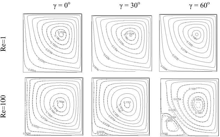
Fig. 3. Stream function for partially heated side walls with inclination angle between -90 and -30 and Reynolds numbers equal to 1 and 100 at Richardson number 3.
γ = 0
oγ = 30
oγ = 60
oR
e=
1
R
e=
100
Fig. 4. Stream function for partially heated side walls with inclination angle between 0 and 60 and Reynolds numbers equal to 1 and 100 at Richardson number 3.
Isotherms depict some curves whose center is in
the left corner for Richardson=1. When Richardson increases to 10, isotherms are closer to each other
near the hot surfaces and total heat transfer augments
307
A.A.Abbasian Arani et al./ JNS 2 (2012) 301-311
are given in Fig. 10 for γ =-60o. It is observed that
Num increases by the increment of Reynolds number
and nanoparticle concentration. Also enhancement in
Richardson number results in enhancement of Num. Fig. 11 shows Num for all cases under study at
Richardson from 0.1 to 10, Reynolds number between 1 and 100 versus angle of inclination and
solid volume fraction from 0.0 to 0.6. The Num
increases by increasing of solid volume fraction for
all cases under study. While the cavity inclination varies, Num changes as mentioned. This change is
very small for Ri=0.1, Figs 11b, d, h, because in this
case forced convection is dominate and angle of
inclination dose not effect on average Nusselt
number. The value of average Nusselt number increases by increasing the Reynolds number from 1
to 100 in these cases, about 400%. Same situation has been occurs for Reynolds number equal to 1 for
all Richardson number under study, Figs 11a, b, and
11e, f. The value of average Nusselt number is
constant versus angle of inclination and Richardson number.
γ = 90
oRe=1
Re=10
Re=50
Re=100
Fig. 5. Stream function for partially heated side walls with inclination angle 90 and Reynolds numbers from 1 to 100 at Richardson number 3.
γ =
-90
oγ =
-60
oγ =
-30
oR
e=
1
R
e=
100
308
A.A.Abbasian Arani et al./ JNS 2 (2012) 301-311
γ =0
oγ =30
oγ =60
oR
e=
1
R
e=
100
Fig. 7. Temperature contours for partially heated side walls with inclination angle between 0 and 60 and Reynolds numbers equal to 1 and 100 at Richardson number 3.
γ = 90
oRe=1
Re=10
Re=50
Re=100
Fig. 8. Temperature contours for partially heated side walls with inclination angle 90 and Reynolds numbers from 1 to 100 at Richardson number 3.
In this situation natural convection is dominate and
for this type of boundary condition (constant
temperature on bottom and left walls) change of
inclination angle has no effects on natural convection. In addition Reynolds number is low,
then shear force is small and when this force is opposite to Buoyancy force, it has no effect on total
Nusselt number.
For Reynolds number equal to 10, 50 and 100, Num
increases by increasing of inclination angle from -90o
to -30o, Fig 11c, g, f, and k. By changing of
inclination angle from -30o to 0o and then to 60o, as
mentioned, Num reduces. Then by enhancement of
inclination angle to 90o, Num decreases for Richardson number equal to 3 and
increases/decreases for Richardson number equal to 7 and 10. As natural convection is lower than force
convection, Num reduces at these angles at
309
A.A.Abbasian Arani et al./ JNS 2 (2012) 301-311
5. Conclusion
This work focused on mixed convection (combined
forced and natural convection) through an Al2O3–
water in a double lid-driven square cavity with various inclination angles and discrete heat sources.
In this study a number of simulations for a wide
range of the controlling parameters consist of Richardson number, Reynolds number, inclination
angle of cavity, and solid volume fraction were
performed.
The results are presented in the form of streamline,
isotherm and Nusselt number plots. The Num
increases by increase of solid volume fraction for all
cases under study. At low Reynolds numbers or low
Richardson number, Num variations are very small
and don't change for some cases at all. The value of
average Nusselt number increases by increasing the Reynolds number from 1 to 100 at Ri=0.1, about
400%.For Reynolds number equal to 10, 50 and 100, Num increases by increasing of inclination angle
from -90o to -30o. By changing of inclination angle
from -30o to 0o and then to 60o, as mentioned, Num
reduces. Then by enhancement of inclination angle to 90o, Num decreases for Richardson equal to 3 and
increases/decreases for Richardson number equal to 7 and 10.
Re=1
Re=100
R
i=
0.
1
R
i=
10
Fig. 9. Stream function and temperature contours for partially heated side walls with inclination angle 30, Reynolds numbers 1 and 10 and Richardson number equal to 0.1 and 10.
310
A.A.Abbasian Arani et al./ JNS 2 (2012) 301-311
Fig. 10.Average Nusselt number at γ =-60o for various nanoparticles concentration versus Richardson number.
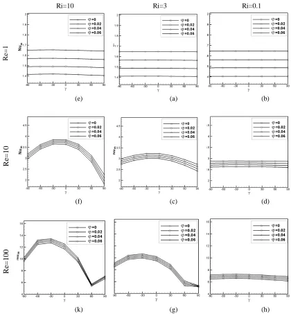
Ri=10 Ri=3 Ri=0.1
Re
=
1
(e) (a) (b)
R
e=
10
(f) (c) (d)
R
e=
100
(k) (g) (h)
Fig. 12. Average Nusselt number at Richardson number 0.1 and 3, for Reynolds number from 1 to 100 versus inclination angle.
Acknowledgments
The authors would like to thank the referees for
their valuable comments. The authors are grateful to
University of Kashan for supporting this work by Grant No. 158506. They would also like to thank the
Iranian Nanotechnology Development Committee for their financial support.
Nomenclature
cp specific heat, J kg -1
K-1 g gravitational acceleration, m s-2
311
A.A.Abbasian Arani et al./ JNS 2 (2012) 301-311
k thermal conductivity, W m-1 K-1
L cavity height and width, m
Nu Nusselt number
p pressure, N m-2
P dimensionless pressure
Pr Prandtl number q heat flux, W m-2
Ra Rayleigh number
Re Reynolds number
Ri Richardson number
T dimensional temperature, K
u, v dimensional velocities components in x and y direction, m s-1
U, V dimensionless velocities components in X and
Y direction
U0 lid velocity
x, y dimensional Cartesian coordinates, m
X, Y dimensionless Cartesian coordinates
Greek symbols
α thermal diffusivity, m2 s
β thermal expansion coefficient, K-1
θ dimensionless temperature
μ dynamic viscosity, kg m-1 s
ν kinematic viscosity, m2 s
ρ density, kg m-3
φ volume fraction of the nanoparticles
γ Inclination angle
Subscripts
c cold
f fluid
h hot
h hot
m average
s solid particles
w wall
References
[1] T. Basak, S. Roy, P.K. Sharma, I. Pop, Int. J. Therm. Sci. 48 (2009) 891–912.
[2] G. Guo, M.A.R. Sharif, Int. J. Therm. Sci. 43 (2004) 465–475.
[3] R.K. Tiwari, M.K. Das, Int. J. Heat Mass Trans.
50 (2007) 2002–2018.
[4] M.A.R. Sharif, Appl. Therm. Eng. 27 (2007) 1036–1042.
[5] P. Kandaswamy, S. Sivasankaran, N. Nithyadevi, Int. J. Heat Mass Trans. 50 (2007) 942-948.
[6] B. Ghasemi, S.M. Aminossadati, Num. Heat
Trans. Part A 54 (2008) 726-743.
[7] Y. Xuan, Q. Li, J. Heat Trans. 125 (2003) 151– 155.
[8] S. Choi, ASME Publications 66 (1995) 99–105. [9] M. Muthtamilselvan, P. Kandaswamy, J. Lee,
Commun. Nonlinear Sci. Num. Simulation. 15 (6)
(2010), 1501-1510.
[10] A.A. Abbasian Arani, S. Mazrouei Sebdani, M.
Mahmoodi, A. Ardeshiri, M. Aliakbari, Superlattices
and Microstructures 51 (6) (2012) 893–911.
[11] C.J. Ho, M.W. Chen, Z.W. Li, Int. J. Heat Mass
Trans. 51 (17-18) (2008) 4506-4516.
[12] E. Abu-Nada, Int. J. Heat Fluid Flow 30 (4) (2009) 679-690.
[13] H.C. Brinkman, J. Chem. Phys. 20 (1952) 571–
581.
[14] J. Maxwell, A Treatise on Electricity and
Magnetism, second ed. Oxford University Press,
Cambridge, UK, 1904.
[15] S.V. Patankar, Numerical Heat Transfer and
Fluid Flow, Hemisphere Pub. Co., Washington, DC,