Available at http://www.ijcsonline.com/
Integration of Wavelet Transformation and Statistical Coding for Image
Compression with Tiling
Dr. Vivek Aggarwal Ȧ*, Manpreet SinghḂ and Dr. Anupama GuptaĊ
Lala Lajpat Rai Institute of Engineering and Technology, Moga-142001 (Punjab) India
Abstract
In this era of rising technologies, storage and transmission has become integral and important part of everyone's life as a result of its easier, quicker and safer use. The aim of this paper is to come back up with a method of image compression with effective size reduction but keeping the quality intact. Image compression has many applications, for example, in medical imaging, space photography and film industry. In this paper, an efficient image compression scheme for RGB images has been proposed. The scheme first divides the image into tiles, then decomposes images using Haar wavelet compression method and finally uses the Huffman encoding algorithm to encode these sequences. Tiling process in the present study is not a fixed one but number of tiles varies with the size of the images which ensures better compression. The experimental results show that by combining image decomposition and encoding methods, the proposed scheme can achieve competitive compression performance compared to the previous studies.
Keywords: Compression, Haar wavelet, Huffman encoding, Fourier transform, Correlation
I. INTRODUCTION
Image compression techniques reduce the irrelevance and redundancy of the image data in order to be able to store or transmit data in an efficient form. Image compression is a process of decreasing size in bytes without compromising with the image quality upto below par level. The compressed images have advantage over uncompressed images in low memory requirement for storage and also reduction of to be sent over the Internet or downloaded from Web pages. It is the useful process that saves a lot of space and resources while sending images from one place to another. It eliminates the redundant part and functions which can be generated at the time of decompression. Hence, the compression of images plays an important role for efficient storage and transmission [1]. The main goal is to achieve higher compression ratios and minimum degradation in quality [2].
II. IMAGE COMPRESSION SYSTEM The basic system for the purpose of compression is represented and its various methods are given. Later on, the hybrid technique of discrete cosine transform is discussed. The discrete cosine transform belongs to the family of sinusoidal unitary transforms. They are real, orthogonal and separable with fast algorithms for its computation.
A. Image Compression Model
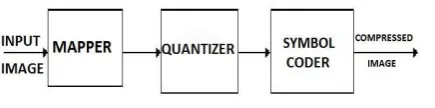
The compression system removes the redundancies from the images through a sequence of three independent operations. In the initial stage, an image is fed into the mapper, which reduces spatial and temporal redundancy from the image. The function of a Quantizer is to keep the irrelevant information out of the compressed form. In the final stage, the symbol coder generates a fixed-length or variable-length code to represent the quantizer output and maps the output according to the code [3]. The model of image compression system is shown below in Fig. 1.
Figure 1: Image Compression model
B. Image Tiling
The primary preprocessing task is tiling. In this progression, the input information in the form of an image is divided into a number of rectangular non-overlapping squares if the image is large sized. Each of these squares is known as a tile. Each tile has exactly the same measurement with the exception of the tiles at the outer margins of image. The tile sizes can be self-assertive up to the measure of the input image. For an image with various parts, every tile likewise comprises of these segments. For a grayscale picture, the tile has a solitary part. There is formation of noticeable changes at the margins of the image when using block transformation coding because of independent compression of all tiles. Small sized tiles have disadvantage as these create more margin artifacts and also decrease the efficiency of compression while large tiles don’t do so. Then again, if the tile size is too expensive, it requires bigger memory buffers for usage either by programming or equipment. For very large scale integration (VLSI) execution, it requires extensive on-chip memory to cushion vast tiles for the most part for wavelet transformation computation.
C. Image Compression Techniques
Compression. In Lossless Compression, the original image can be reconstructed from the compressed image. These techniques are widely used in medical imaging since they do not add noise to an image [4]. On the other hand, in Lossy compression technique, the reconstructed image contains some degradation as compared to the original one but it is nearly close to it. Lossy compression produce some compession by-products when used at low bit rates. This technique provides much higher compression ratios than the lossless scheme [5]. Some Lossless and Looosy data compression techniques are mentioned below:
i. Lossless Techniques
Run-Length encoding
Huffman encoding
Arithmetic coding
LZW coding
Area coding
ii. Lossy Techniques
Transform coding (DCT/DFT)
Predictive coding
Wavelet coding
D. Haar Wavelet
Haar wavelet compression is a proficient approach to perform both lossless and lossy picture compression. It depends on averaging and differencing values in a picture grid to create a matrix that is sparse or almost sparse. A sparse matrix is a matrix in which a substantial part of its entrances are zeros. A sparse matrix can be put away in a productive way, prompting least document sizes. In these notes, we will focus on grayscale pictures, be that as it may, RGB pictures can be taken care of by compressing each of the color layers independently.
The basic strategy is to begin with a picture A, which can be viewed as a m × n framework with values 0 to 255. In MATLAB, this would be a network with unsigned 8-bit whole number qualities. Then, the picture is subdivided into 8 × 8 pieces, padding as important. It is these 8 × 8 obstructs that have been worked with. Consider a case of 8 × 8 blocks.
The first row of this block is:
A= {88 88 89 90 92 94 96 97}
The transformation process will occur in three steps. The first step is to group all of the columns in pairs:
[88, 88], [89, 90], [92, 94], [96, 97]
Then, replace the first 4 columns of r1 with the average of these pairs and replace the last 4 columns of r1 with 1/2 of the difference of these pairs. This new row is denoted as r1h1:
r1h1 = 88 89.5 93 96.5 0 −0.5 −1 −0.5
The first 4 entries are called the approximation coefficients and the last 4 are called detail coefficients. The Haar wavelet change can be utilized to perform lossy compression so that the compressed picture holds its quality. In the first place, the compression ratio of a picture is the proportion of the non-zero components in the first to the non-zero components in the compressed picture.
E. Huffman Encoding
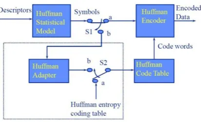
The Huffman coding is a lossless data compression technique for removing the coding redundancy. It uses a small number of bits to encode common characters. Huffman coding approximates the probability for each character as a power of 1/2 to avoid complications associated with using a nonintegral number of bits to encode characters using their actual probabilities. The Huffman encoding is uniquely decodable and instantaneous because the code symbols in a string can be decoded in one way only and without referencing any succeeding symbols. It creates optimal code for a set of symbols and probabilities subject to the constraint that the symbols can be coded one at a time [6-8]. The Huffman code procedure is based on the fact that the symbols which occur more frequently have shorter code words than symbols which occur less frequently. Also, the two symbols which occur least frequently will have the same length [9]. The schematic of Huffman Encoder Scheme is shown in Fig. 2.
Figure 2: Huffman Encoder Scheme
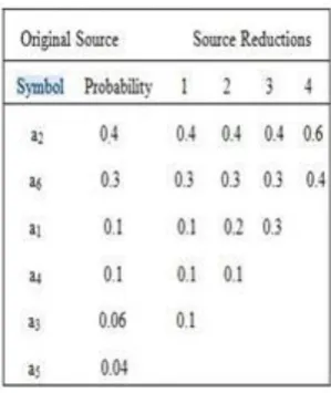
compound symbols is left. This is shown by an example in Table 1.
Table 1: Huffman Source Reductions
At the far left of the Table 1 a series of source symbols is listed and their corresponding probability is arranged in their decreasing order. The first source reduction is formed by merging the lowest two probabilities, 0.06 and 0.04 and this yields the probability of 0.1, which is placed in the first column of the source reductions. The probabilities are placed such that they are always in their decreasing order. This process is repeated until the two probabilities, 0.6 and 0.4 are left at the end as shown in the last column of source reduction. The second step in this method is to generate a code tree starting with the smallest source and going back towards the original source [10-12]. This is illustrated by procedure listed in Table 2.
Table 2: Huffman Code Assignment Procedure
The minimum length of binary code for a two-symbol source is the symbols 0 and 1. The reduced source symbol with probability 0.6 was generated by merging the two symbols in the reduced source to its left, the 0 which was used to code it is now assigned to both its symbols and these symbols are further appended by adding a and 1 to each of them so that they can be distinguished from each
other. This procedure is repeated until the final code is produced at the far left of the Table 2.
The average length of the code is given by:
Lavg = (0.4)(1) + (0.3)(2) + (0.1)(3) + (0.1)(4) + (0.06)(5) +
(0.04)(5)
= 2.2 bits/symbol
Entropy of the source is 2.14 bits/symbol. The resulting Huffman code efficiency is 2.14/2.2=0.973.
Entropy, H = ( )
)
(ai
log
ajL
K
P
P
F. Huffman Decoding
The process of decompression involves the prefix codes stream translation to individual byte values, usually by reading each bit from input stream and traversing the Huffman tree node by node. The reconstruction of Huffman tree must take place for this process. Preconstruction of tree could take place in the case of predictable character frequencies and at the expense of at least some measure of compression efficiency, is reusable every time. Otherwise, tree reconstruction information is to be sent a priori. To prepend each character to the compression stream on the basis of frequency count, a naive approach might be used. If the canonical encoding is used in data compression, then reconstruction of compression model can be done with just B 2 B bits of information where number of bits are represented by B.
One more way is to prepend Huffman tree to the output stream bit by bit. For example, 0 is assumed as the value representing a parent node and a leaf node is represented by 1, tree building routine reads the next 8 bits on encounter of latter for character value determination of particular leaf. Huffman tree is reconstructed on reaching last leaf node, until then the process continues. Many other techniques are possible as well. The decompressor must be able to determine when to stop producing output since the compressed data can include unused "trailing bits". By defining a special code symbol to signify the end of input or by either transmitting the length of the decompressed data along with the compression model, this can be accomplished [13-14].
III. PROPOSEDALGORITHM
The research started with the study of images. Then, random RGB images were taken into consideration. In the process, a hybrid system of Haar wavelet and Huffman coding has been generated. First, tiling of the image has been performed and then, Haar wavelet is implemented on all the tiles.
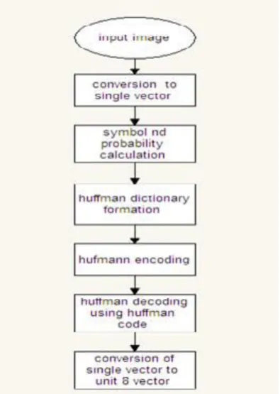
probability and symbols. Then using probability and symbol, we created the Huffman dictionary. Then, after generation of a new vector and using dictionary along with it, Huffman encoding is done. This compresses the unit 8 image into a single vector in the form of Huffman code. Then, in decoding process by using Huffman code and dictionary, we decoded image and that is the final results of our process.
.
Figure 3: Flowchart showing the whole hybrid system of
Haar Wavelet and Huffman encoding
A. Huffman Algorithm Steps
The stepwise procedure of Huffman algorithm is as follows:
i. Output of Haar wavelet is taken as input in Huffman algorithm.
ii. Dictionary formation using probability and symbol.
iii. Huffmann encoding of the dictionary
iv. Huffman decoding by using Huffman code and Huffman tree reconstruction.
v. Output as unit8 image.
Figure 4: Flowchart showing the Huffman process in
detail with encoding and decoding.
After implementation of this algorithm, the various parameters have been computed and results are generated. The quantitative parameters used in the experimental study are signal-to-noise ratio (SNR), peak signal-to-noise-ration (PSNR), mean square error (MSE), bit error rate (BER) and correlation coefficient (CC).
IV. RESULTS
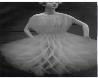
Figure 5: Original image ‘Dancer’
Figure 6: Tiles of image ‘Dancer’
Figure 7: Final image after compression process of Haar
Wavelet and Huffman hybrid algorithm.
we have calculated various metrics such as SNR, PSNR, MSE, BER and CC to support and validate the proposed research. These values have been listed in Table 3. The results reveal that a very less mean square error value, and bit error rate have been achieved by our process as compared to many previous researches. Further, the peak signal-to-noise ratio is also considerably higher than what has been achieved in the previous studies. Moreover, the significant increase in CC is also evident and it indicates that the proposed algorithm works efficiently for the RGB images.
Table 3: SNR, PSNR, MSE, CC and BER values after the
application of proposed and existing schemes.
SNR PSNR MSE CC BER Proposed
Method (Fractal)
37.52 46.22 1.47 0.9997 0.3388
DPCM + Huffman
19.41 38.17 9.91 0.8233 0.4139 DWT
(Haar) + Huffman
20.30 38.54 9.11 0.8345 0.5388
DPCM + DWT (db1) + Huffman
14.23 30.20 62.09 0.8143 0.5453
DPCM + DWT (db4) + Huffman
15.78 32.90 33.38 0.7845 0.7665
DPCM + DWT (Haar) + Huffman
14.23 30.20 62.09 0.8009 0.9122
V. CONCLUSIONS
In this work, an efficient hybrid image compression algorithm is developed. To efficiently compress images, firstly, the Haar Wavelet technique is used in all red, green and blue constituents independently. Then, the output from the haar wavelet is used as input to Huffman encoding process which works on probabilities and symbols from the values of pixels. This data encoding scheme works fine with wavelet technique to bring about efficient compression. Further, we tested the efficiency and relativity of our process by implementing the performance metrics like SNR, PSNR, MSE, BER and CC. It is evident from the experimental results that the proposed process shows better SNR and PSNR as compared to previous work. Bit error rate and correlation coefficient results show that the proposed scheme has competitive compression performance on all kind of RGB images compared to previous studies. Our scheme provides an interesting progressive transmission feature for image compression as well.
REFERENCES
[1] Gonzales, R. C., & Woods, R. E. Digital Image Processing. 2002. New Jersey: Prentice Hall, 6, 681.
[2] Subramanya, A. (2001). Image compression technique. IEEE potentials, 20(1), 19-23.
[3] Rathee, M., Alka Vij, M., & Scholar, T. (2014). Image compression Using Discrete Haar Wavelet Transforms. International Journal of Engineering and Innovative Technology (IJEIT) Volume, 3. [4] Lai, C. C., & Tsai, C. C. (2010). Digital image watermarking using
discrete wavelet transform and singular value decomposition. IEEE Transactions on instrumentation and measurement, 59(11), 3060-3063.
and Computing Research (ICCIC), 2013 IEEE International Conference on (pp. 1-5). IEEE.
[6] Malviya, S., Gupta, N., & Shirvastava, V. (2013, July). 2D-discrete walsh wavelet transform for image compression with arithmetic coding. In Computing, Communications and Networking Technologies (ICCCNT), 2013 Fourth International Conference on (pp. 1-4). IEEE.
[7] Daubechies, I. (1992). Ten lectures on wavelets, vol. 61 of CBMS-NSF Regional Conference Series in Applied Mathematics. [8] Thepade, S. D., Dewan, J. H., Suryawanshi, B., & Erandole, S. S.
(2015, September). Vector quantization based image compression with Kekre, Walsh and Slant Wavelet transforms in Thepade's Transform Error Vector Rotation codebooks. In 2015 IEEE Bombay Section Symposium (IBSS) (pp. 1-6). IEEE.
[9] Leung, T., Marcellin, M. W., & Bilgin, A. (2013, March). Visually Lossless Compression of Windowed Images. In Data Compression Conference (DCC), 2013 (pp. 504-504). IEEE.
[10] Ernawan, F., Noersasongko, E., & Abu, N. A. (2011, December). An efficient 2× 2 Tchebichef moments for mobile image compression. In Intelligent Signal Processing and Communications Systems (ISPACS), 2011 International Symposium on (pp. 1-5). IEEE.
[11] Shi, Z., Sun, X., & Wu, F. (2013, November). Multi-model prediction for image set compression. In Visual Communications and Image Processing (VCIP), 2013 (pp. 1-6). IEEE.
[12] Patil, N. K., Murgod, S. F., Boregowda, L., & Udupi, V. R. (2013, March). Adaptive texture and color feature based color image compression. In Smart Structures and Systems (ICSSS), 2013 IEEE International Conference on (pp. 82-86). IEEE.
[13] Parmar, C. K., & Pancholi, K. A Review on Image Compression Techniques. Journal of Information, Knowledge & Research in Electrical Engineering, 2(2), 281-284.