the knuckle coupler pin while no relevant problem is defined and possible remedy is determined
________________________________________________________________________________________________________
I.PROBLEM FORMULATION
The main motive of this paper is to improve the performance of the knuckle pin in the couplings of the railway couplings. The current mechanism of coupling is briefly defined and methodologically treatment is determined for failure of knuckle pin in the coupling. The aim of this chapter is to conceptually define remedy for the failure problem of the knuckle coupling.
II.WORKING OF THE MECHANISM
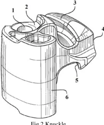
The knuckle coupling forms the interlinking in between any of the wagons in railways. The figure 1 presents the mechanism of the knuckle couplings with its various components nomenclature.
Fig 1 the mechanism of the knuckle couplings
As shown in the above fig. clear vision of knuckle, knuckle pin and the coupler is available. As per the functionality of these three components the coupler is main connector with the wagon of any railway coach, engine, etc. The knuckle is the actual load transferor in between the couplings and the function of the knuckle pin is to hold the knuckle at the position while knuckle is under fluctuating load of wagons. The maximum loading is of 47000 kg (461070 N). The individual component with relevant problem of failure is as explained
Fig 3 Top View of Knuckle
Fig 6 Isometric view of coupler
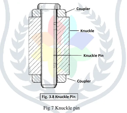
The knuckle pin assembled in the knuckle coupling joint is shown in the figure 3.8. As mentioned earlier the knuckle pin is for retaining of the knuckle – coupler assembly. The possible failure of knuckle pin is in shearing of the pin. The complete assembly of the joint is in figure.
Fig 7 Knuckle pin
Fig 8 Assembly structure of knuckle coupling joint
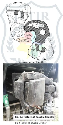
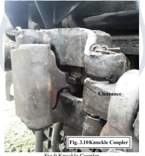
The figure 9 shows the actual assembly of knuckle coupler. The problem identified is within the knuckle where at the posterior of the knuckle at the contact at the guide way slot the clearance is providing the unnecessary displacement in the knuckle with respective to the coupler of approximate 5 mm. This defect is caused due to possible reasons including manufacturability of the knuckle and/or coupler. The another possible reason could be the sliding of the knuckle and coupler causing surface to be deformed and creating clearance.
Fig 9 Knuckle Coupler
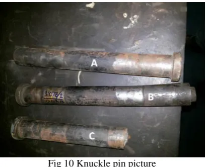
Fig 10 Knuckle pin picture
The Knuckle pin shown in figure 10 are showing the failure of knuckle pin in shear. The further analysis of the problem is studied and possible solution is provided in next chapter.
III.KNUCKLE PIN DESIGN
Traditional and finite element method describes the possible failure and elasticity requirement of the material
Shear failure of pin
Area testing shear failure =π/4d² Τ= p/2(π/4d²) or d=√ πτ τ=permissible shear stress τ =461070/ 2(π/4*4l²) =461070
=174.6136 N/mm²
Crushing failure of Pin Compressive stress – c =
=
=60.136 N/mm²
Crushing failure of pin in coupler– Бc = = = =93.71 N/mm²
Bending Failure of pin Mb= ( +X) - (z)
Failure occur due to shear when the pin is loose for triangular distribution of load X =1/3*60 & z = ¼*187
Mb= ( +X) - (z)
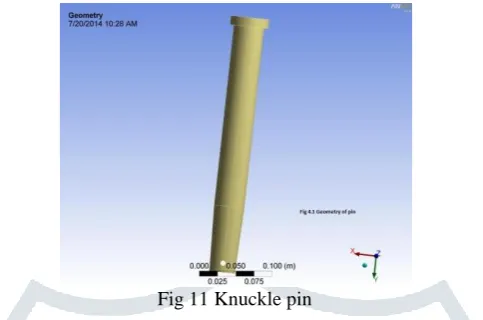
Fig 11 Knuckle pin
As per the contact surface of knuckle and coupler the length wise contact areas are defined as from top 60 mm for coupler, next 187 mm shaft for knuckle and again next 60 mm for coupler.
Constraining of the geometry is necessary as per the contact defined in previous paragraph. The coupler is rigid representing the wagon condition and the knuckle length is constrained for displacement of 5 mm defining the clearance in-between the knuckle and coupler. The load condition applied of 47 tons which is the maximum working load condition. The analysis undertaken is under static analysis as the deflection caused is due to fluctuating condition of the knuckle and coupler is to be represented. The Analysis results are determined in the figures below. The Figure 12 shows the Deformation of knuckle pin under loading condition as per the constraining mentioned above. The results of deformation show the maximum of deflection of 5 mm which is equivalent to the clearance in between the knuckle and coupler. The bending results explain the behaviour of the knuckle pin.
Fig 12 the Deformation of knuckle pin
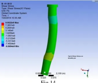
The figure 13 determines the stress evolved in the knuckle pin. The Von-Mises stress are to be recognised for the maximum stress conditions. The stress locations are recognised as the shearing planes at the mating planes of the coupler and knuckle.
Fig 14
The results and discussions determine the application of the alternate material availability for the knuckle pin with requirement of deformability of 5 mm without failure. A proper elastic material can be used instead steel to withstand the required condition and sustain the accurate functionality of the problem.
V.RESULTS AND DISCUSSIONS
As per the defined conditions and analysis the present steel material can be substituted with a proper elastic material. The presently for the problem of shear failure of the pin alternatively plastic knuckle pin that will accept bending fatigue, thereby reducing pin failure can be used. The pin made of a plastic material having a flexibilitythat will allow it to bend and return to its original shape and to also be self- lubricating. Further, the pin eliminates rust and corrosion and produces a low coefficient of friction between the pin and the coupler body and knuckle, thus enhancing opening and closing of the knuckle by reducing rotational resistance, thereby promoting safety. It has been known that steel pins, either at the time of installation or after service, can cause a “lazy knuckle”, i.e., a knuckle that will not open all the way on decoupling. Thereafter, it is usually impossible for the knuckle to close in a coupling operation which necessitates a yard worker to reach in with his hand and pull the knuckle into fully open position, and usually when another car is coming to couple. While it is against the rules to pull open a knuckle under those circumstances, the worker often tries, which many times has resulted in the worker’s hand and/or arm being injured and even taken off.
REFERENCES
[1] Knuckle structure for coupler by Horst Thomas Kaufhold, Chicago on 31st Dec., 1974
[2] Knuckle structure to prevent knuckle pin failure in a railway coupler presented by William O. Elliott & Pittsburgh on 3rd Feb., 1987
[3] Knuckle structure to ensure failure at Knuckle throat portion by William O. Elliott & Pittsburgh on 14th March, 1989 [4] Coupler knuckle pin protector structure and stress reliever by Russell G. Altherr 8449 Moraine Ave. Munster, Ind. 46321
on 15th Feb. 1994
[5] Railroad coupling knuckle hoist and method by E. B. Delcambre and Fort Smith on 25th July. 1995
[6] Knuckle coupler pin by Jeffrey D. Wurzer, Turtle Crec, PA(US), Joseph L. Gagliardino, Oakdale, PA (US) on 3rd Dec., 2002