Abstract— The advancement of the rapid prototyping (RP) technologies evolving toward rapid tooling in producing sacrificial patterns rapidly has profoundly benefits the investment casting (IC) process. Direct expendable pattern fabrication via RP techniques in complex and intricate features significantly reduce the cost when associated with single or low volume production. However inappropriate settings of the RP processes and its variables may cause serious defect in the ceramic shell such as cracking during burning out of the patterns, incomplete collapsibility and poor qualities of end products. By implementing the ANOVA at 95% confidence level to study the relative influence of factors and interactions, result shows that Surface Roughness (SR) and Dimensional Accuracy (DA) drastically
affected by input variables within 5 % level of significance. Confirmation runs for all responses were carried out to ensure that the models reliability. The error level for ABS P400 was within reasonable range with less than 19%. It is also found that Visijet SR200 acrylate have better variation below than 14%. This study was conducted in an effort to exploit the application of various RP tand materials in the fabrication of IC patterns by utilizing the RP process parameters in minimizing the errors of responses. Moreover, it is expected that this study will provide valuable information and great assistance to the IC manufacturer in producing precise, low cost and rapid patterns using RP technologies.
Index Term— Direct Investment Casting, Fused Deposition
Modeling, Rapid Prototyping, Multijet Modeling, RP Process Parameters.
I. INTRODUCTION
Investment casting (IC) is one the approach to produce quality near net shape of metal parts that proficient of providing a cost-effective means of mass fabrication. For that
O. M. F. Marwah is from the Faculty of Mechanical and Manufacturing Engineering at Universiti Tun Hussein Onn Malaysia (UTHM) (phone:
+6011-10761897 e-mail: [email protected]). S. Sharif is from the Faculty of Mechanical Engineering at Universiti
Teknologi Malaysia (UTM) (e-mail: [email protected]).
M. S. Shukri is from the Universiti Tun Hussein Onn Malaysia (UTHM) (e-mail: [email protected]).
E.J. Mohamad is from the Faculty of Electrical and Electronic Engineering at Universiti Tun Hussein Onn Malaysia (UTHM)
(e-mail:[email protected]).
M.F. Shaari is from the Faculty of Mechanical and Manufacturing Engineering at Universiti Tun Hussein Onn Malaysia (UTHM) (e-mail:
M.Y. Hashim is from the Faculty of Mechanical and Manufacturing Engineering at Universiti Tun Hussein Onn Malaysia (UTHM) (e-mail:
perseverance, wax master patterns have been preferred as the expandable material which can be reprocessed after dewaxing process and lowering material cost. However, when it comes to intricate and multifaceted parts, the use of conventional wax patterns may result in bottleneck due to the slow processing of new pattern preparation that account over 70% of the total lead time [1].
In addition, the high overall cost was driven the need for specialized equipment, cheap refractory and binder materials, reduction of multiple labour intensive steps of mould making. Thus, high tooling cost for hard moulding of wax pattern may not rationalize for customized single and low volume production but usually favored for mass production [2]. Therefore, pattern development and process without the use of hard tooling from the early inception has encouraged Rapid Prototyping (RP) technology to be used in IC process. Currently, almost all commercialized AM techniques have been employed to produce IC patterns with various success and many Rapid Casting (RC) solutions in IC are being used by various industries and researchers [3].
Generally, RP parts have been used in exchange of the traditional wax patterns, resulting in significant quality, time, cost saving and become crucial tool for shortening new product design and optimal cycles time. Consequently, it significantly speeds up the production lead times from simulated to physical prototyping whereby meeting the contemporary approach to alter product development [4-5]. However, RP processes inherit low accuracy and roughness issues contributed from the staircase effect and tessellation of CAD data. Warpage and shrinkage are some quality issues that were investigated by many researchers.
The need to establish a successful inhibiting or suitable process parameters and dewaxing operation on RP patterns is essential to overcome the staircase effect that reflects the surface quality of the final pattern. However, the evaluation of RP part quality is generally avoided even in the most relevant case studies, building times or cost whereby the focus of the majority of benchmark studies is undertaken. Only a few studies have compared and reported in detail the overall quality of IC parts produced out of RP sacrificial patterns [6].
Many studies conducted have evaluated the FDM and 3DP using different materials and process parameters. However, the studies on the comparison between ABS produced by FDM Prodigy Waterworks System and Visijet SR200 MJM are still limited. Furthermore, there is still a lack of literature on the
Process Parameters Evaluation for Direct
Investment Casting
evaluation of qualities for acrylate droplet concept as mentioned by Cazon [7] especially on MJM for Visijet.
Despite the many benefits that can be achieved through Rapid Prototyping and Tooling (RP&T) techniques, rapid tooling is still behind conventional tooling in terms of quality and performance. The issues pertaining dimensional accuracy and surface quality are still the issues that need to be further addressed continuously [8].
To meet the demand for cost effective solutions and shorter fabrication time in small quantity casting production, researchers and equipment builders look outside the bounds of the traditional wax based IC process. RP process produces direct sacrificial patterns with the aims of achieving acceptable pattern quality without shell cracking to produce solid metal parts during the IC process.
II. METHODOLOGY
A. Routes for direct RP in IC
The materials used in the FDM are thermoplastic such as ABS, polycarbonate and polyphenylsulfone which builds the parts in the same robust, stable plastics used in injection moulding and other traditional manufacturing processes. The overall concept of FDM uses two different materials in the building process. A primary part material is used to fabricate the model geometry and the secondary support material, or release material, is used to produce the support structures. FDM constructs the parts by movable temperature controlled head which extrude thermoplastic material onto a platform. The heated nozzles are used to lay down the molten part built filaments and support the materials in the desired cross sectional geometries as shown in Figure 1 FDM has been directly or indirectly used in investment casting. The direct investment casting application uses the FDM ABS plastic parts which are treated with metal spray as the investment casting patterns. Meanwhile the indirect investment casting application produces RTV moulds from FDM plastic parts first; then creates wax investment casting patterns from RTV moulds [9]. The surface finishing of FDM parts is not very smooth. Therefore, the surface of the final investment casting parts is also influenced. The combination of strength for FDM parts between each layer is weak, which hinders FDM technology to be used in sand casting pattern manufacturing. FDM technology also takes a long time to make a large part.
Similar to the concept of FDM techniques, multi jet modelling (MJM) used jetting head spray with tiny droplets of melted liquid deposited of photopolymer which cool and harden to form solid object as shown in Figure 2 RP ink jet techniques utilize ink jet technology to shoot droplets of liquid-to-solid compound and form a layer of an RP model. The system generates wax-like plastics models. The machine uses multiple spray nozzles with wide head area that spray droplets of melted liquid which could cool and harden into solid objects. Generally, MJM technology combines acrylic build material and wax based support materials which melt easily leaving the required patterns.
B. Pattern Design and Fabrication
The STL data format for the interface between CAD and RP is an industry de facto standard. The prototype model consists of a simple geometry with a “stairstep” as shown in Figure 3. This shape allows the investigation on the effect of various thicknesses on the casting behaviour. Besides that, rectangular and square shapes are easily to measure as well as handling the patterns. For ensuring the steady and precise data obtained the design should be simple, low utilization of resources and simplify the use of measuring instruments as well as low interest on material usage [9-11].
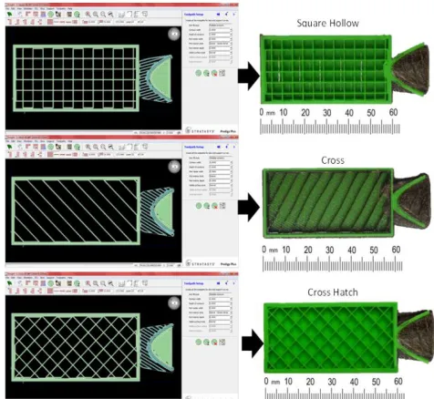
The internal structure was intended to permit simple evacuation of the molten RP material during the burnout process from the ceramic mould. Hence, the structure should
Fig. 1. Schematic of Fused Deposition Modeling.
sufficiently solid to give the support, yet sufficiently frail to collapse early underneath the expansion and permit complete drainage. In imperative for a structured design to be appropriate for investment casting it should be developed in accordance with the following criteria stated by Hague [12] such as be robust to support the part during building, strong enough to support the general handling of the part, weak enough to collapse under the influence of its own expansion as well as allows complete drainage. Figure 4 shows the internal design structure of RP fabricated parts.
The advantages of RP techniques are they have 100% interconnected porous structure with no trapped material problem and able to build intricate complex structure. However, FDM is less able to build complex structures
compared to SLA machine. MJM did not provide software for creating internal structure. Hence, by adopting the internal structure may cause materials to be trapped and lack of mechanical strength with no chemical bonding. These limitations can be overcome by using manual-based CAD technique for MJM except for FDM in which incorporate Insight software. Therefore, building a novel build style would produce a series of interlinked voids, consequently with low viscosity and would decompose effectively during the burnout process.
III. RESULT AND DISCUSSION
A. Significance Parameters Analysis for ABS P400 FDM
Prodigy WSS
According to the fractional factorial design, sixteen runs of experiments were undertaken for ABS P400 FDM Prodigy WSS. The coded and real values of the input parameters are identified and presented in Table 1 such as layer thickness (LT), raster angle (RA), road width (RW), .air gap (AG) and part orientation (PO) respectively. Corresponding data of the two response variables for dimensional accuracies (DA) and
surface roughness (SR) were evaluated and recorded as shown
in the respective Table 1 and Table 2. Response analysis is made at 95% confidence level to study the relative influence of factors and interactions using ANOVA. The total degree of freedom of five factors each at two levels and four interaction terms were used to analyse the significant parameters. Probability is greater than the calculated value due to noise indicated by the p value. If p value is less than 0.05, significance of the corresponding term is established. For lack of fit, the p value must be greater than 0.05. An insignificant lack of fit is desirable as it indicate anything left out of the model is not significant and hence, the model fits.
It was observed that significant factors and interactions for different responses shows that where the probability P < 0.05, there are two model terms which are LT and RW. LT results indicate that the P value is 0.000, hence the chance that the model could be wrong is non-existent, making the parameters significant. So far, a 5% level of significance model is adequate. PO and interaction LT*PO are considered significant model terms that influence the Dimensional accuracy (DA) of end parts. Similar finding shows LT and RW
were the significant parameters was reported by Sood [13] when using FDM Vantage SE. With reference to the ANOVA test in Table 1 it is clears that R2pred. is 74.01% which is not at
all close to R2adj of 90.86%. This indicates that the interaction
formed couples with the model reduction and it could improve the predictive model. Table 1 and Table 2 show the ANOVA results of ABS P400 FDM Prodigy for DA and SR respectively.
Fig. 4. Internal view structure of fabricated RP parts. Fig. 3. Detail drawing of ‘Stairstep’ features for hollow internal
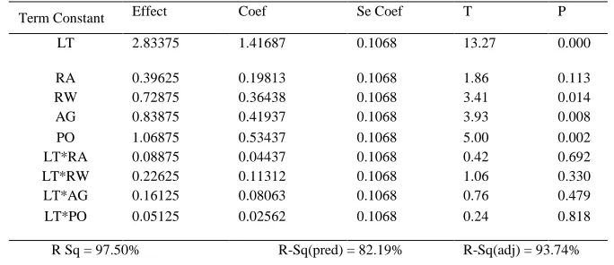
According to the ANOVA results shown in Table II, for Surface roughness (SR), the numbers indicate that LT, PO, AG
and RW are significant factors. This is according to the fact that the P value < 0.05 which shows that at the5% level of significance, the first order model is adequate. LT, PO and AG have the most influence on surface roughness of the ABS P400 patterns. The results are similar to previous research which showed that LT and PO are the most significant parameters on SR as mentioned by V. Bharathet [14] and Pandey [15] for
ABS FDM1650. Moreover the RSq and R2adj are high and very
close to each other. However the R2pred was not close to R2adj
but still high at 82.19%.
B. Significance Parameters Analysis for Acrylate Visijet
SR200 MJM.
The Acrylate Visijet SR200 part has been fabricated using the MJM Projet SD3000. Two process parameters consisting of part orientation (PO) and part position were considered for this system. At 22 numbers of factors, the total number of runs equal to 4 runs only. In this design, three replications consisting of 12 runs were considered for the experiments. The coded and real values of the input parameters for Visijet SR200 acrylate part were identified and presented in Table 3 Table 4.
Corresponding data on the two response variables for dimensional accuracies (DA) and surface roughness (SR) were evaluated and recorded as shown in Table 3 and Table 4.
Probabilities greater than the calculated value due to noise is indicated using the p value. If a p value is less than 0.05, the corresponding term’s significance is established. For lack of fit the p value obtained must be greater the 0.05. An insignificant lack of fit is desirable as it indicates that anything left out of the model is insignificant. The ANOVA table for Visijet SR200 are presented in Table III and Table IV for DA and SR
respectively.
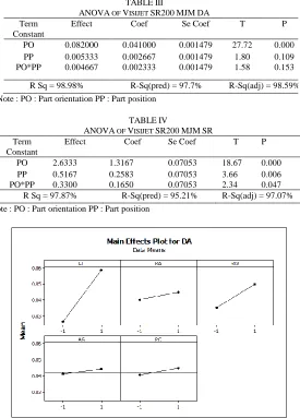
The ANOVA results shown in Table 3, indicates that part orientation (PO) is the only significant factor that influence the dimensional accuracy (DA) with probability, P < 0.05. The R2predand R2adjwere both high at 97.7 % and 98.59 %
respectively, thus implying that the model are accepted. Table 3 shows the ANOVA of Visijet SR200 MJM for DA.
ANOVA results shown in Table 4 indicate that both the factor PO and their interactions are significant to SR for Visijet
SR 200 acrylate parts. This is due to the fact that the P values were less than 0.05, thus the first order model is adequate. Moreover the R2pred.and R
2
adj are high and very close to each
other for both models. This implies that there was no such scope of elimination of any significant terms from the model. TABLEI
ANOVA OF ABSP400FDMPRODIGY FOR DA
Term Constant Effect Coef Se Coef T P
LT 0.032000 0.016000 0.001475 10.85 0.000 RA 0.004750 0.002375 0.001475 1.61 0.158
RW 0.014250 0.007125 0.001475 4.83 0.003 AG 0.003000 0.001500 0.001475 1.02 0.348
PO 0.004250 0.002125 0.001475 1.44 0.200
LT*RA 0.006500 0.003250 0.001475 2.20 0.070 LT*RW -0.005500 -0.002750 0.001475 -1.86 0.111 LT*AG -0.001250 -0.000625 0.001475 -0.42 0.686
LT*PO 0.005000 0.002500 0.001475 1.70 0.141
R Sq = 96.35%
R-Sq(pred) = 74.01%
R-Sq(adj) = 90.86% Note ; LT : Layer thickness, PO : Part orientation, RA : Raster angle, RW : Raster width, AG : Air gap
TABLEII
ANOVA OF ABSP400FDMPRODIGY FOR SR
Term Constant Effect Coef Se Coef T P
LT 2.83375 1.41687 0.1068 13.27 0.000
RA 0.39625 0.19813 0.1068 1.86 0.113 RW 0.72875 0.36438 0.1068 3.41 0.014 AG 0.83875 0.41937 0.1068 3.93 0.008 PO 1.06875 0.53437 0.1068 5.00 0.002 LT*RA 0.08875 0.04437 0.1068 0.42 0.692 LT*RW 0.22625 0.11312 0.1068 1.06 0.330 LT*AG 0.16125 0.08063 0.1068 0.76 0.479 LT*PO 0.05125 0.02562 0.1068 0.24 0.818
R Sq = 97.50% R-Sq(pred) = 82.19% R-Sq(adj) = 93.74%
C. Main Effect Plot Analysis for ABS P400 FDM Prodigy WSS
A main effect plot is the effect of a single independent variable on a dependent variable ignoring all other independent variables. This graph shows the average outcome for each value of each variable, combining the effects of other variables as if all variables are independent. Two significance parameters for dimensional accuracy (DA) were further analyze in order to perform optimum setting conditions. From the analysis, it was found that quality of parts is significantly affected by layer thickness (LT). As observed the main effect plot result for dimensional accuracies (DA) showed that the
optimum conditions has to be at low level to obtain minimal ABS P400 part accuracies for layer thickness (LT). Increment of layer thickness determines the height of the stair step. The lesser the layer thickness the closer it is to the original dimension in CAD data and therefore the lesser the height of the stair step produced on the prototype. Furthermore, the raster width (RW) also results in better
accuracy whereby lower RW is better. Minimal RW will deposit a thin head of extruded plastics side by side within the domain boundary. Figure 5 shows the main effect plot for dimensional accuracy (DA) of FDM.
The main effect plots for surface roughness (SR) and the
corresponding variables are shown in Figure 6. From the plots implies that, in order to obtain better surface, the variables LT, AG, RW and PO should be set at lower levels. LT parameters were found to be the most influencing factor in reducing the ABS P400 part surface roughness compared to other variables. It has been demonstrated through correlation analysis that an inverse relation exists between layer thickness and surface roughness [16]. On contrary, lower process parameters settings tend to improve the surface roughness (SR). The surface
roughness was reported to be smaller for downward surfaces compared to upward surface. Usually, the staircase effect is observed on the side surface of the FDM parts due to part orientation and layer thickness. While building FDM parts, an outer contour is deposited followed by raster filing of interior region. However, the profile of the outer contour is a curvature instead of flat profile and hence outer contour contributes to TABLEIV
ANOVA OF VISIJET SR200MJMSR Term
Constant
Effect Coef Se Coef T P
PO 2.6333 1.3167 0.07053 18.67 0.000 PP 0.5167 0.2583 0.07053 3.66 0.006 PO*PP 0.3300 0.1650 0.07053 2.34 0.047 R Sq = 97.87% R-Sq(pred) = 95.21% R-Sq(adj) = 97.07% Note : PO : Part orientation PP : Part position
Fig. 5. The Main Effect Plot for Dimensional Accuracy (DA) of FDM. TABLEIII
ANOVA OF VISIJET SR200MJMDA Term
Constant
Effect Coef Se Coef T P
PO 0.082000 0.041000 0.001479 27.72 0.000 PP 0.005333 0.002667 0.001479 1.80 0.109 PO*PP 0.004667 0.002333 0.001479 1.58 0.153
the roughness inside surfaces. Adjusting AG from negative to positive decrease the material consumed considerably. This can be explained by the resultant increase in spacing between road widths hence increasing the roughness. Figure 6 shows the main plot effect for Surface Roughness (SR) of FDM.
D. Main Effect Plot Analysis for Acrylate Visijet SR200
MJM
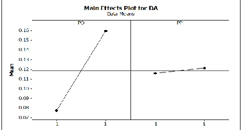
It was observed that from the main effect plot in Figure 7 and Figure 8, the factor part orientation (PO) is the most significant factor affecting the dimensional accuracy (DA) and
surface roughness (SR) respectively. The result in Figure 7
clearly shows that for dimensional accuracies (DA), the
optimum conditions for Visijet SR200 part accuracies (PO) have to be set at low levels. Similarly, PO should be set at a minimum position to obtain better roughness of the RP parts. The orientation of parts tends to alter the inclination of certain faces of the fabricated part. The orientation of a part in the optimal direction induces a relatively smaller angle between the facets and the build direction, resulting in a lower surface roughness. Therefore, the vertical walls or surfaces of the RP parts have the best surface finish or the least surface roughness followed by the horizontal surfaces. Orientation can thus be used as a tool to moderate the undesirable stair stepping effect. Figure 7 and Figure 8 shows the main effects plot for DA and SR of Visijet SR200 MJM respectively.
E. Confirmation Runs of Responses
Confirmation runs to obtain experimental data can be used to verify and optimize responses. By randomly conducting several runs, verification and validation can be performed. Initially, some specific RP fabrication parameters were chosen within the limits adopted in the experimental design. An experiment was conducted to evaluate the actual response and then compared with the predictive model value, calculating for the percentage of error.
As evident, the ABS P400 FDM revealed the highest percentage of error with a range of 13.36 % to 18.75 % compared to MJM with recorded values of 5.1 % to 13.36 % for both DA and SR respectively.
IV. CONCLUSION
This study reveals that the combination of rapid prototyping and investment casting is a suitable process for the rapid manufacture of direct castings. The capabilities of this manufacturing process have been studied and comparison was performed between the two types of RP processes which include ABS P400 materials and Visijet SR200 acrylate using FDM Prodigy WSS and MJM Projet SD3000 techniques. Confirmation runs for all responses were carried out to ensure that the model reliability. The error level for ABS P400 was within reasonable range with less than 19%. It is also found that Visijet SR200 acrylate have better variation below than 14%.
Different internal pattern structures were design and fabricated and tested to evaluate the effect on accuracy and part surface roughness. Effect of different internal part structure on the RP part fabrication revealed that has lower deviation compared to hollow pattern. However, it was found
Fig. 8. The Main Effect Plot for Surface Roughness (SR) of MJM.
Fig. 6. The Main Effect Plot for Surface Roughness (SR) of FDM..
TABLEV CONFIRMATION RUNS RESPONSE
RP
systems Responses
Predicted Value
Overall Confirmatio
n Runs
Percentage of Error %
FDM DA (mm) 0.016 0.013 18.75 SR (µm) 5.876 5.091 13.36
that the internal structure did not have much effect on the part surface roughness which part accuracies can be improved. Overall results showed that, Visijet SR200 acrylate part was considered superior in terms of part surface qualities compared to ABS P400 patterns.
The empirical models developed for the RP pattern fabrication which include dimensional accuracy and surface roughness are reliable and can be applied in practical. The response optimizer plots created by utilizing Minitab software can readily be used for multi-criteria optimization.
ACKNOWLEDGMENT
The authors wish to thank Ministry of Education Malaysia for funded Fundamental Research Grant Scheme (FRGS) Vot1423 and Faculty of Mechanical & Manufacturing Engineering in Universiti Tun Hussein Onn Malaysia (UTHM) for facilitating and financial support to this research programme.
REFERENCES
[1] D.K.Pal, T. K., B. Raychaudhuri, K. Ravi and Subburaj, (2007). Rapid tooling route selection and evaluation for sand and investment casting.
13th International Conference on Advanced Research in Virtual and
Rapid Prototyping, 455-463.
[2] Vaezi, M., D. Safaeian and C. K. Chua, (2011). Gas turbine blade manufacturing by use of epoxy resin tooling and silicone rubber molding techniques. Rapid Prototyping Journal, 17, 107-115. [3] Chhabra, M. and R. Singh, (2011). Rapid casting solutions: A review.
Rapid Prototyping Journal, 17(5), 328-350.
[4] Shan, Z., Y. Yan, R. Zhang, Q. Lu and L. Guan, (2003). Rapid manufacture of metal tooling by rapid prototyping. International
Journal of Advanced Manufacturing Technology, 21, 469-475.
[5] Xing Ai, J., C. Li and Huang., (2004). Integrated product design using Rapid Prototyping Technology and Rapid Tooling in Concurrent Approach. Materials Science Forum, 471-472, 672-676.
[6] Charmeux, J.-F. (2007). Capabilities of the Investment Casting process for producing meso/micro metal castings using Rapid Prototyping manufacturing routes. PhD, Cardiff University.
[7] Cazón, A., P. Morer and L. Matey, (2014). PolyJet technology for product prototyping: Tensile strength and surface roughness properties.
Proceedings of the Institution of Mechanical Engineers, Part B:
Journal of Engineering Manufacture.
[8] Cheah, C. M., C. K. Chua, C. W. Lee, C. Feng and K. Totong, (2005). Rapid prototyping and tooling techniques: A review of applications for rapid investment casting. International Journal of Advanced
Manufacturing Technology, 25, 308-320.
[9] Colin Gouldsen, P. and Blake. (1998). Investment Casting Using
FDM/ABS Rapid Prototype Patterns. USA.
[10] Zhou, J. G., D. Herscovici and C. C. Chen, (2000). Parametric process optimization to improve the accuracy of rapid prototyped stereolithography parts. International Journal of Machine Tools and
Manufacture, 40, 363-379.
[11] R.Hague, S. M., N.Saleh, (2004). Material and design considerations for rapid manufacturing. International Journal of Production Research, 42(22), 4691-4708
[12] Hague, R. and P. M. Dickens, (2001). Improvements in investment casting with stereolithography patterns. Proceedings of the Institution of
Mechanical Engineers, Part B: Journal of Engineering Manufacture,
215, 1-11.
[13] Sood, A. K., R. K. Ohdar and S. S. Mahapatra, (2010). Parametric appraisal of fused deposition modelling process using the grey Taguchi method. Proceedings of the Institution of Mechanical Engineers, Part
B: Journal of Engineering Manufacture, 224(1), 135-145.
[14] V. Bharath, P. N., M. Dharma and Henderson. (2000)," Sensitivity of RP Surface Finish to Process Parameter Variation," Solid Free Form
Fabrication Proceedings.
[15] Pandey, P. M., N. V. Reddy and S. G. Dhande, (2003). Improvement of surface finish by staircase machining in fused deposition modeling.
Journal of Materials Processing Technology, 132, 323-331.