Abstract—Speed controls design of electric vehicle (EV). The control circuit using PSO, Fuzzy& PI controller is proposed. Driven EV's is powered by a n electric motor, the EV is powered by PMSM. Electric vehicle is simulated in MATLAB SIMULINK. Simulation tools are great assistance to engineers and researchers to reduce product-development cycle time, improve the quality of the design, and simplify the analysis without costly and time-consuming experiments. There are many power electronic converters and motor drives connected together to form the electrical system of an Electric Vehicle. In this paper, we have presented a modeling tool that has the advantages of utilizing capabilities of the PMSM software in detailed simulations of converters, motor drives, and electric machines. In addition, equivalent electrical models of Electric Vehicle drive system. This paper also gives a brief idea of PMSM validity as an Electric Vehicle simulation tool. This paper, simulation PMSM model to apply Electric Vehicle drive system. PMSM drive system is described and analyzed due to its importance in many applications especially in Electric Vehicle applications. Applications due to their high efficiency, low inertia and high torque to volume ratio. A closed loop control system with a PI control, Fuzzy and PSO in the speed loop with current controllers. The simulation circuits for PMSM, inverter, speed and current controllers include all realistic components of the drive system. Simulation results for SPWM control schemes associated with current controllers are given for two speeds, one below rated and another above rated speed. In this paper and it has been shown that the model is suitable for transient as well as steady state condition. These results also confirmed that the transient torque and current never exceed the maximum permissible value.
Index Terms—Electric vehicle drive system, permanent magnet synchronous motors (PMSM), PI controller, fuzzy logic (FL) and particle swarm optimization (PSO).
I. INTRODUCTION
A novel speed control design of electric vehicle (EV) to improve the comportment and stability under different road constraints condition [1]. The PMSM, it has significant advantages, attracting the interest of researchers and industry for use in many applications, that uses permanent magnets to produce the air gap magnetic field rather than using electromagnets[2]. The PMSM, with high level energy permanent magnet materials particularly provide fast dynamics, efficient operation and good compatibility with
Manuscript received September 16, 2015; revised November 25, 2015. This work was supported in part by the State Key Laboratory of Advanced Electromagnetic Engineering and Technology,Wuhan, China,Huazhong University of Science & Technology (HUST), Hubei, China.
The authors are with School of Electrical and Electronic Engineering, Huazhong University of Science and Technology (HUST), Hubei, China (e-mail: [email protected]).
the applications but only if they are controlled properly. The controller is using in order to overcome the nonlinearity problem of PMSM and also to achieve faster response [3]. Many industrial applications require new control techniques, the techniques used, applied in all regulation loops, speed regulation of permanent magnet synchronous machine (PMSM) [4]. The development of power electronics and electric Technology, PMSM for extensive applications in many control systems. And PMSM, which are commonly used for systems and control devices minute owns several advantages over other machines on Milan. Advantages PMSM include large torque coefficient, and high efficiency, high energy density, and a torque multiplier is small, Low-inertia, low noise, and high performance in a wide variety [5]. A way controller (PI) in addition to the controllers with integral relative formulated and implemented, using speed control magnet synchronous motor drive system and a permanent pilot phase. While the new strategy promotes traditional PI control performance to a large extent, and proves to be a model-free approach completely, it also keeps the structure and features of a simple PI control [6]. The use console mode instead of Fuzzy-PI control to improve the performance of engines PMSM. To control the speed of PMSM motor using fuzzy logic (FL) approach leads to a speed control to improve the dynamic behavior of the motor drive system and immune disorders to download and parameter variations [7]. In the electric vehicle drive systems, and gains from the tradition can’t usually be set in proportion-integral (PI) controller speed large enough because of mechanical resonance. As a result, performance degradation and speed control. In our work described in this paper, have been adopted and fuzzy logic controller (FLC) for use in electric vehicle drive systems in order to improve the performance of the speed control. The proposed FLC has been compared with traditional PI control with respect to the speed of response and dynamic load torque. Simulation and experimental results have proved that FLC was proposed is superior to the traditional PI. This FLC can be a good solution for high-performance engine lifts systems [8]. A modern approach to control the speed of PMSM using particle swarm optimization (PSO) to improve the algorithm parameters observer PI-. Simulate the system under different operating year conditions is prepared and the experimental setup. Use PSO algorithm and optimization make a powerful engine, with faster response and higher resolution dynamic and sensitive to load variation [9].
Fig. 1 shows Block diagram of a PMSM and Fig. 2 shows block diagram of a PMSM Drive.
Artificial Optimal Fuzzy Control Strategy for Electric
Vehicle Drive System by Using Permanent Magnet
Synchronous Motor
A. Salam Waley, Chengxiong Mao, and C. Dan Wang
The complete nonlinear model of a PMSM without damper windings is as follows:
s
=
+
+
(
+
)
q q q q d d af
v
Ri pL i
L i
(1)s
=
+
-d d d q q
v
Ri pλ
L i
(2)vd and vq are the d, q axis voltages, id and iq are the d, q
axis stator currents, Ld and Lq are the d, q axis inductances, R
and
s are the stator resistance and inverter frequency respectively.
afis the flux linkage due to the rotor magnets linking the stator.The electric torque:
3 (
(
-
)
)/2
e af q d q d q
T
P
i
L
L i i
(3)The motor dynamics:
-
e L r r
T T
B
Jp
(4)P is the number of pole pairs, TL is the load torque, B is the damping coefficient,
ris the rotor speed and J the moment of inertia. The inverter frequency is related to the rotor speed as follows:r
s
p
(5)The machine model is nonlinear as it contains product terms such as speed with id and iq. Note that
r,id and iq are state variables. During vector control, id is normally forced to be zero
3
/2
e af q t q
T
Pλ i
K i
(6)Fig. 1. Block diagram of a PMSM.
Fig. 2. Block diagram of a PMSM drive.
III. ARTIFICIAL OPTIMAL FUZZY CONTROL STRATEGY BY
SPEED CONTROL OF PMSMMOTOR
The PMSM is using control to suppress harmonic noise to a level. Then, noi
s
e to a level below and vibration translates into a more comfortable ride for passengers. IGBT SPWM inverters make the ride smoother with precisely adjustingspeed control with frequency and voltage regulation. It has the latest low-noise power units to make the ride even quieter. Electric Vehicle (EV) has directed high-speed used (1500 rpm) PMSM. Energy reform in the Electric Vehicle geared for small rise because travel extremely small and fast.
Fig. 3. Block Diagram of speed control of PMSM.
A. PI Controller Modeling
In the PI speed controller the motor speed is compared with the reference speed and the speed error is the nth sampling interval as
e
[n]
r[n] -
r[n]
(7) The output of the speed controller gives the reference torque. Hence the output of the speed controller at the nth sampling interval is[ ]
[ -1]
( [ ]- [ -1]) Ki [ ]
e e eT n
T n
Kp
n
n
n
(8)For constant air gap flux operation reference quadrature axis current is given as
*
[ ]/
q
i
T n Kt
(9)The limiter is used to limit the maximum value of output of speed controller. The maximum motor rated current and device current of the converter dictate the limit.
where, ωe [n] is speed error at nth instant, ωr*[n] is the reference speed at nth instant
ωr[n] is the actual motor speed at nth instant, ωe[n-1] is the speed error at (n-1)th instant
T[n] is the reference torque at nth instant, T[n-1] is the reference torque at (n-1)th instant
Kp is proportional gain of the speed controller
Ki is integral gain of the speed controller is reference quadrature axis current
Kt is torque constant
B. Fuzzy Logic Controller
The Basic configuration of a Fuzzy Logic Controller (FLC) consists of the following components:
1) Fuzzification Interface 2) Knowledge Base (KB) 3) Decision Making Logic 4) Defuzzification Interface
module series is closed by a general discussion about the contribution of fuzzy control. For a PM motor drive system with a full speed range, the system will consist of a motor, an inverter, controller (constant torque and flux weakening operation, generation of reference currents and PI controller).
C. Particle Swarm Optimization
It is a technique used to explore the search space for a given problem to find the settings or parameters required to optimize a particular objective. PSO has two main concepts: the first is through the observation of human decision making, it was proposed that humans use both their own best experience and others’ best experience to form a basis of making a decision, to develop the concepts of individual learning and cultural transmission. The second is to propose a simple theory to explain group behavior in nature, and to popularize the theory to create systems to simulate things. The biggest characteristic of PSO is in its simple structure, fast convergence, and its ability to prevent falling into a local optimum solution. At the same time, PSO is a random algorithm with a parallel structure. Firstly, a uniform distribution is used to randomly make a particle swarm.
Each particle is a feasible solution to the problem, the particle swarm refers to the individual’s best experience, and the group’s best experience, and logically chooses the method it will move itself. After continuous iterations, the particle swarm will gravitate towards the optimum solution.
IV. ELECTRIC VEHICLE (EV)SYSTEM
The diagram of an Electric Vehicle (EV) system using a PMSM supplied by voltage inverter. Electric Vehicle (EV) system as in Fig.4 and the vehicle up a slope as in Fig. 5:
Fig. 4. Electric vehicle (EV) system.
A. The Vehicle Load
The vehicle inertia torque defined by the following relationship:
Tin = Jv(dwv/dt) (9)
B. Aerodynamics Force
The force is due to the friction of the vehicle body, moving through the air.
Faero = (ρSTxv2)/2 (10) The aerodynamics torque is:
Taero = (ρSTxRrv2)/2 (11)
C. Rolling Force
The rolling resistance is primarily due to the traction of the tire on the rode. It is proportional to vehicle weight. The
equation is:
Ftire = Mgfr (12) The rolling torque is:
Ttire = MgfrRw (13)
D. Hill Climbing Force
The force needed to drive the vehicle up a slope is the most straightforward to find.
Fslope = Mgsin(β) (14) The slope torque is:
Tslope = Mgsin(β)Rw (15)
Fig. 5. The vehicle up a slope.
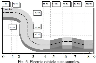
E. Electric Vehicle State Samples
In Fig. 6 we find this state: Paths of Electric Vehicle: Vehicle driven on a straight road, vehicle driven on a straight road with a slope, and vehicle driven over a road curved left and right.
Fig. 6. Electric vehicle state samples.
F. Electric Vehicle has Submitted a Number of Tests During the Various Routes
1) The speed flows precisely the acceleration ramp at (0<t<(t1)), Electromagnetic torque decrease and settle around (T1) Nm and EV gives the same speed (s1). 2) The speed increase from (s1)km/h to (s2) km/h at (t=(t2). 3) Electromagnetic torque around (T2) Nm at ((t2) <t <
(t3)s).
4) The vehicle is driving on a curved road on the right side at (t = (t3)s) .
5) The EV are driving in straight road with constant speed, EV reaches constant speed (s2)km/h at ((t3) < t < (t4)s). 6) The vehicle is driving on a curved road on the left side
with (s3)km/h speed, Turn in the same direction but with different speeds at (t=(t5)).
7) The EV are driving in straight road, The EV torque jumps down to (T3) Nm at ( (t5)s < t < (t6)s)
the slope on the EV at ((t7)s < t < (t8)s) develops Approximately (T4)Nm, The EV torque reach to (T5) Nm
9) This test explain the effect of the slope on the EV at ((t8)s < t < (t9)s), The speed maintain to (s4) km/h, The EV torque jumps back to (T5) Nm.
10)At (t10)s < t < (t11)s, EV are driving in straight road, Speed vehicle settles at (s1) km/h, and EV torque increase to (T6) Nm.
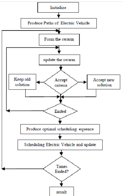
G. Electric Vehicle Control System Application Flow Chart
TheSteps are showed as follows (flow chart as Fig. 7):
Fig. 7. Electric vehicle control system application flow chart.
Step 1: Create the parameters of the Electric Vehicle Drive system.
Step 2: According to the call signal and the current situation Electric Vehicle Drive system.
Step 3: By Reload squadron by using update value-weighted inertial, with the speed of convergence.
Step 4: Use the acceptance criteria, to decide whether to accept these new particles or not, and to increase the diversity of the particles, with avoid trapping in local Optimization.
Step 5: The end of the iteration, then the global search the optimal solution. If not, step loop (3).
Step 6: By using Loop to step (2) until the end time simulation, then output the result.
V. SIMULATION RESULTS
By using Simulation model PMSM, Simulation of Electric Vehicle Drive system by using PMSM:
A. Simulation Model PMSM.
Model of the system is verified through computer simulations using the software Electric Vehicle MATLAB/Simulink. Summarizes the performance of the Electric Vehicle Drive system, both in computer simulation and experimental implementation. The analyzed Electric Vehicle considers electrical drive (PMSM Drive System). Electric Vehicle motor is three-phase PMSM with. Drive converter is current regulated SPWM voltage source inverter (CRSPWM VSI) direct current power supply. The positioning system and position controller of Electric Vehicle are used for the task to provide position reference tracking and zero error in steady state. Constant load is usual for one Electric Vehicle ride. Thus, a position controller with proportional and integral action (PI) is used, block diagram of PI Controller is shown in Fig. 8. Parameters of real Electric Vehicle with PMSM drive were included in the model of Electric Vehicle.
Fig. 8. PI controller.
Simulation of the entire system with the designed controller is made in the Matlab/Simulink and given results show that design controller meets the requirements completely smooth and precise position and speed. Input parameters for the dynamic of the Electric Vehicle are:
Te Motor traction torque 238 Nm
Je Moment on inertia of the drive train 7.07 Kgm2
Rw Wheel radius 0.32 m
a Total gear ratio 10.0
η Total transmission efficiency 0.93
M Vehicle mass 1300 Kg
fe Bearing friction coefficient 0.32
Kd Aerodynamic coefficient 0.32
A Vehicle frontal area 2.60 m2
fv Vehicle friction coefficient 0.01
α Grade angle of the road Rad
Lw Distance between two wheels and axes 2.5 m
dw Distance between the back and the front wheel 1.5 m To verify the feasibility of control, PMSM drive simulation model with control is created and studied using MATLAB. Simulation parameters: stator resistance Rs = 0.01Ω, inductance Ld = Lq = 0.01835H, flux Ψ = 0.4 V.s, pair of poles p = 3, inertia J = 0.029kg.m2. Simulation conditions: reference speed n = 1500 rad / s, start with TL = 5N.m. Simulation results are shown in Fig. 10 speed, Torque and current, It is obvious that correct responses of speed, current, and torque in control system. Using PSO, Fuzzy and PI control has a good application in PMSM drive. At the same time, with speed have faster response. Ripple of torque is obviously reduced. So the system performance is improved.
B. Simulation of EV Drive System by Using PMSM
0 0.5 1 1.5 2 2.5 3 3.5 -200
0 200 400 600 800 1000 1200 1400 1600
Time(sec)
Speed(rad/
sec
)
(a). Speed. (b). Torque.
(a). Modelling for PI speed controller of PMSM.
(b).Modelling for fuzzy speed controllerof PMSM.
0 0.5 1 1.5 2 2.5 3 3.5 4 -30
-20 -10 0 10 20 30 40
Time
C
ur
re
nt
Iabc
(c). Phase current.
Fig. 10. Speed, torque and current response, n=(0,1500 ,0)rad/s &TL = 10N.m.
(a). Speed.
(b). Torque.
0 1 2 3 4 5 6 7 8
-30 -20 -10 0 10 20 30
Time(sec)
C
u
rr
e
n
t(
Ia
,I
b
,I
c
)
(c). Phase current.
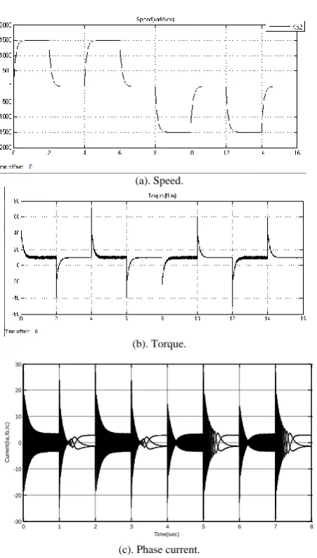
Fig. 11. Speed, torque, current response, n = (0, 1500, 0, 1500, 0, -1500, 0, -1500, 0 )rad / s & TL= 10N.m.
Firstly case: Electric Vehicle move with (0, 1500) in this case (Stop and driving in straight road with constant speed) we can see the speed signal, it change with minimum value to maximum value (transient and steady), then we can look to the Torque and Current to see the change its.
Secondly case: Electric Vehicle move with (0, 1500, 0) it change three states (Stop, driving in straight road with constant speed and Stop).
Thirdly case: Electric Vehicle move with (driving in straight road with constant speed) two sides (0, 1500,-1500) in this case (Stop and driving in straight road with constant speed with two sides) it mean zero is Stop state, 1st side state at (1500) and 2nd side state at (-1500), then we can look to the Torque and Current to see the change its.
Finally, there are two states it has different in Torque (no load, constant and variable) with it a current is change.
1) Electric Vehicle move with a Speed is variable &a Torque is Constant.(as show in Fig. 11)
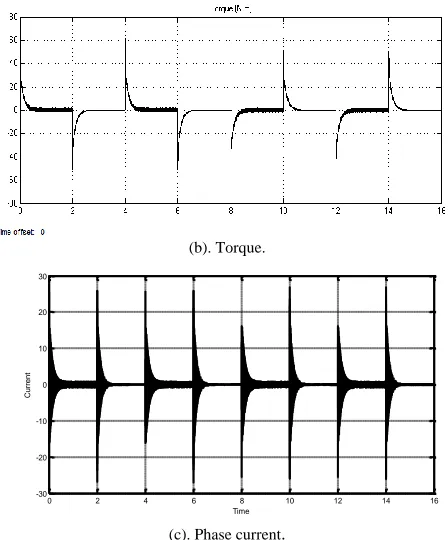
2) Electric Vehicle move with a Speed is variable &a Torque is variable. (As show in Fig. 12)
3) Electric Vehicle move with a Speed is variable &a Torque is equal 0N.m (no load). (As show in Fig. 13).
(a). Speed.
(b). Torque.
0 2 4 6 8 10 12 14 16
-30 -20 -10 0 10 20 30 40
Time
C
u
rr
e
n
t
Iabc
(c). Phase current.
Fig. 12. Speed, Torque& Current Response, n = (0, 1500, 0, 1500, 0, -1500, 0, -1500, 0) rad /s &TL = (10, 5, 10, 5) N.m, a torque is variable.
(b). Torque.
0 2 4 6 8 10 12 14 16
-30 -20 -10 0 10 20 30
Time
C
u
rr
e
n
t
Iabc
(c). Phase current.
Fig. 13. Speed, torque and current response, n =(0, 1500, 0, 1500, 0,-1500, 0, -1500,0)rad / s &TL = 0N. m a torque is equal zero 0N.m (no load).
(a). Speed response.
(b). Torque response.
(c). Current response.
Fig. 14. Speed, torque & current response with one side at speed (500,600,400,500).
(a). Speed response.
(b). Torque response.
time offset 0
(c). Current response.
Fig. 15 Speed, torque, current response with two sides at speed (500,1000,1500,-500,-1000,-1500).
C. Simulation of Electric Vehicle Drive System
Electric vehicle has submitted a number of tests during the various routes:
This test clarify the effect of the descent of vehicle moving on straight road, This test explain the effect of the slope on the EV, EV torque increase, the EV are driving in straight road with constant speed, the speed increase, the vehicle is driving on a curved road on the right side, the EV torque jumps down, the vehicle is driving on a curved road on the left side and EV torque jumps back.
In the Fig. 14. There are three part: 1st: speed, 2nd: Torque and 3rd: Current When the status of speed (500, 600, 400, 500),The status Torque about (10, 11, 9, 10),The status Current about (6, 7, 5, 6).
(b). Torque response.
time offset 0
(c). Current response.
Fig. 16. Speed, torque, current response with one side at speed (500,1000,1500).
VI. CONCLUSION
PSO_Fuzzy_PI control is able to adapt itself the suitable control parameters which are the proportional and integral gains kp and ki to the variations of vehicle torque. This method was Improved EV steering and stability during different trajectory this. The advantage controller is robustness and performance, with no overshoot and stability of vehicle perfected ensured with the speed variation and less error speed. with adaptive PSO_Fuzzy_PI controller is more adaptive for propelled systems. The electric vehicle was proved best comportment and stability during different road path by maintaining the motorization error speed equal zeros and gives a good distribution for deriving forces. The electric vehicle was proved efficiency comportment in the different road constraints. This paper will cover the simulation, and implementation of a PMSM controlled by a control system to drive an Electric vehicle system, the implementation of an Electric vehicle drive by The Electric vehicle drive through the addition of control systems and switching power supplies. Simulation of Electric vehicle drive system by a permanent-magnet synchronous motor (PMSM) is used for this paper. There are some tasks to achieve an Electric vehicle drive, determining the parameters of PMSM, designing a control system to direct the motor as desired, and verifying the performance of the system through use of computer simulations and experimental testing. The implementation of an Electric vehicle driven by a PMSM is successful and provides an illustrative example to those who wish to apply electric drives to various mechanical systems.
REFERENCES
[1] E. Iman, S. Wahsh, and M. A. Badr, "Analysis of PMSM drives for electric vehicles," in Proc. the 37th SICE Annual Conference on International Session Papers, 1998.
[2] B. Kiran, A. M. Kottalil, and N. P. Ananthamoorthy, "Simulation of PMSM vector control system with fuzzy self-adjusting PID controller using matlab," International Journal of Scientific and Research Publications.
[3] D. Yadav, S. Bansal, and M. Kumar, "Design, development and simulation of fuzzy logic controller to control the speed of permanent magnet synchronous motor drive system," Journal of Electrical and Electronics Engineering Research, vol. 3, no. 3, pp: 52-61, 2011. [4] M. T. Benchouia, S. E. Zouzou, A. Golea, and A. Ghamri, "Modeling
and simulation of variable speed drive system with adaptive fuzzy controller application to PMSM," in Proc. 2004 IEEE International Conference on Industrial Technology, pp. 683 - 687.
[5] X. Xi, Y. D. Li, and M. Li, "Performance control of PMSM drives using a self-tuning PID," in Proc.2005 IEEE International Conference, pp. 1053 - 1057 .
[6] F. Parasiliti and D. Q. Zhang, "Real-time gain tuning of PI controllers for high-performance PMSM drives," IEEE Transaction on Industry Applications, vol. 38, no. 4, 2002.
[7] M. Chakraborty, "Comparative analysis of speed control of PMSM using PI-controller and fuzzy controller," International Journal of Scientific and Engineering Research, vol. 4, no. 7, 2013.
[8] U. S. Fazal et al., "Fuzzy gain-scheduling proportional–integral control for improving engine power and speed behavior in a hybrid electric vehicle," IEEE Transactions on Vehicular Technology, 2009. [9] A. S. Elwer and S. A. Wahsh, "Improved performance of permanent
magnet synchronous motor by using particle swarm optimization techniques," Journal of Power Electronics, vol. 9, no. 2, March 2009 .
Salam Waley Shneen received his BSc degree in electrical engineering and education from University of Technology Technical Education Department, Iraq-Baghdad, in 1998. He received his Msc. degree in electrical engineering and education from University of Technology Technical Education Department, Iraq-Baghdad, in 2005. Presently, he is a Ph.D. student in the Department of Electrical Engineering, from Huazhong University of Science and Technology (HUST) since 2013. He joined an assist. lecturer of Electro Mechanical Engineering Department, University of Technology / Baghdad. His fields of interest are power electronic, electronic, control and the excitation control of synchronous generator and applications of high power electronic technology to power system.
Mao Chengxiong received the his B.S., M.S. and Ph.D. degrees in the Department of Electrical Engineering from Huazhong University of Science and Technology (HUST), in 1984, 1987 and 1991 respectively. He was a visiting scholar in University of Calgary, Canada, from Jan. 1989 to Jan. 1990 and in Queen's University of Belfast from Dec. 1994 to Dec. 1995 respectively. He was doing researches in Technische Universitaet Berlin from April 1996 to April 1997 under the support of Humboldt Foundation. Presently, he is a professor of HUST. His fields of interest are power system operation and control, the excitation control of synchronous generator and applications of high power electronic technology to power system.
Dan Wang (M’07) received his B.S., M.S. and Ph. D. degrees in the Department of Electrical Engineering from Huazhong University of Science and Technology (HUST), Hubei, China, in 1999, 2002 and 2006 respectively. He was a postdoctoral researcher from 2006 to 2008, sponsored by China Postdoctoral Science Foundation in the Department of Control Science & Engineering, HUST.