e-ISSN: 2278-7461, p-ISSN: 2319-6491
Volume 6, Issue 5 [May 2017] PP: 06-10
Remaining Life Analysis Of A Steam Boiler Tube
Okpala, Alexander N. and Adigio E.M.
Department of Mechanical Engineering,Niger Delta University,Wilberforce Island, Bayelsa State, Nigeria
ABSTRACT:- Remaining life analysis of a failed in service steam boiler was conducted using Neubauer’s
classification of creep damage. In the course of the study, metallographic analysis and scanning electron microscopy were carried out with the resultant micrographs subjected to Neubauer’s classification of creep damage as contained in ECCC Recommendations, Issue 1.The residual life of the steam boiler was then determined to be 6.75 years. Thorough thicknesssurveywas therefore recommended for the steam boiler tubes to identify portions with severe wall loss for eventual replacement.
KEY WORDS: remaining, life, steam boiler creep, micrographs
I.
INTRODUCTION
Arefinerysteamboilerthathashadahistoryofgoodperformancewithfewleakagesanddamagesthatweresucce ssfullyweldrepaired was observed to have developedseveral perforations/punctures on numerous furnace chamber tubes, twenty two years after commissioning. Given the risks inherent with these failures, a study of the remaining life became imperative to prepare the owners for scheduled replacements. According to Okpala et al (2014), several methods are available for predicting the remaining life of high temperature steel piping. This study however aims at determining the remaining life of a steam boiler tube using metallography and applying the creep life consumption ratio.
Remaining Life Evaluation
Computing estimates of remaining life requires a model of the material damage mechanism. More accurate damage models and knowledge of operating conditions will yield more accurate calculations of remaining life. For an in-service component, the current condition of a component must be determined before remaining life can be estimated. This can be done by using offcuts of undamaged tubes as samples or by insitu-metallography
High-temperature equipment is subject to creep damage during long-term service. As with fatigue,remaining creep life can be evaluated in terms of failure life or in terms of crack-growth life. The formerapproach is most often employed because creep damage is typically associated with the formation ofmultiple voids and micro-cracks, rather than a single dominant crack that can be analyzed using fracturemechanics.
Life assessment
According to Jaske (2002), Life assessment methodology can broadly be classified into three levels. Level 1 methodology is generally employed when service life of the components is less than 80% of their design lives. In level 1, assessments are performed using plant records, design stress and temperatures, and minimum values of material properties from literature. When service life exceeds 80% of the design life, level 2 methodology is employed. It involves actual measurements of dimensions and temperatures, stress calculations and inspections coupled with the use of the minimum material properties from literature. However, when life extension begins after attaining design life, level 3 methodologies is employed. It involves in-depth inspection, stress analysis, plant monitoring and generation of actual material data from samples removed from the component. The details and accuracy of the results increase from level 1 to level 3 but at the same time the cost of life assessment increases. Depending on the extent of information available and the results obtained, the analysis may stop at any level or proceed to the next level as necessary. This study could therefore be classified as level 1 assessment since the boiler tubes have utilized 73% of their design life (that is 22year out of 30 years design life).
Microstructure-based approach:
Remaining Life Analysis Of A Steam Boiler Tube
II.
MATERIAL AND METHOD
Sample:
The sample used for this work was drawn from the steam boiler tube in a refinery that experienced a failure after about 22 years of service life. Records showed that the tube is made up of SA 210 Gr. A1 seamless steel boiler pipe. The operating temperature is 5570C and operating pressure is 52Kg/Cm2 g. Two samples were taken from the tube, labeled A and B. The sample A was taken from the internal of the tube while B was taken from the tube external.
Spectrometric Analysis
TheChemicalanalysisofthetubewascarriedoutusing an optical emission spectrometer which gave the composition presentedinTable 1.
Table1:Chemicalcompositionof steam boiler tube samples
C (%) S(%) P(%) Mn(%) Si(%) Cr(%
)
Ni(% )
Mo(%) Al(%) Cu(%
)
Sample A 0.15 0.010 0.022 0.68 0.21 0.10 0.098 0.025 0.014 0.20
Sample B 0.16 0.009 0.022 0.69 0.23 0.10 0.10 0.025 0.010 0.20
Required 0.27max 0.035max 0.035max 0.93max 0.10min
ThisconformstoASTMSA 210 Gr. A1
MetallographicAnalysis
The perforatedtube samples were prepared for metallography in accordance with ASTM E3, methods of preparation of metallographic specimen. The samples were then observed under metallurgical microscope and the resulting micrographs are presented in plates 1 and 2.
ScanningElectronMicroscopy
SEM wasconductedon samples A and B torevealmore details aboutthe microstructure. The micrographs presented in plates 3 and 4 were obtained.
Creep Level Investigation for The ASTM A 210 Gr.A1 Tubes
The tubes were subjected to metallography and the resultant micrographs were evaluated for creep level.
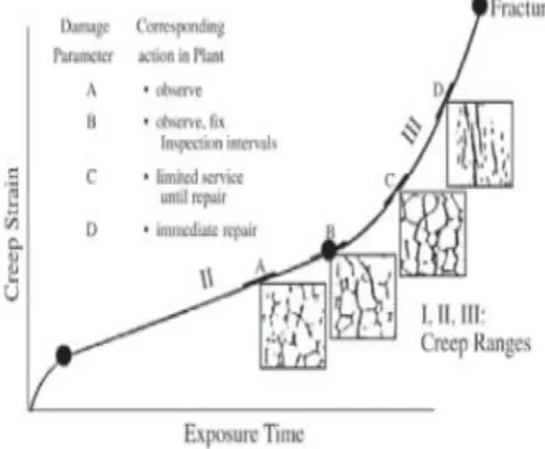
Principle: The creep level investigation was carried out in consonance with the specifications of Neubauer’s classification of creep damage as contained in ECCC Recommendations, Issue 1. This practice classifies creep damage into single cavities/voids, coherent cavities, micro cracks and macro cracks which are superimposed on the creep curve to identify life consumption ratio. This is further depicted by the figures presented in Figures 1, 2 and 3.
Figure 2: Creep Life Consumption ratio depiction
Figure 3: Creep Life Damage Correlation [Source: Mitsubishi Heavy Industries Technical Review Vol. No. 2 (June 2009)]
Class Damage Recommendations precautions
1) Single cavities: Re-Examine after approximate 20000 hours of operation 2) Coherent cavities: Re-Examine after approximate 15000 hours of operation 3) Creep cracks (Micro): Re-Examine after approximate 10000 hours of operation 4) Creep cracks (Macro): the plant is contacted immediately
Remaining Life Analysis Of A Steam Boiler Tube
Plate 1: Micrographs of Sample A Showing Creep Cavity/Micro-cracks500x
Plate 4: SEM Micrograph of sample B
III.
CONCLUSION
Whereas sample A has a residual life of 59,130 hours, sample B has a residual life of 98,550 hours. It shows that sample B will live out the boiler life while sample A will not since the remaining life of the boiler is 70,080 hours.Since the boiler tube was designed for 30 years’ service life, it is therefore imperative thatthe tube from which sample A was drawn has a residual life of 6.75 years [59,130/(365 x 24)] while the tube from which sample B was drawnhas a residual life of 11.25years[98,550/(365 x 24)].
The remaining life of the steam boiler is therefore 6.75 years.
IV.
RECOMMENDATIONS
Thorough thicknesssurveywastherefore recommended for the steam boilertubes to identify portions with severe wall loss for replacement. Since the creep level study presented indicate that sample B will live out the boiler life while sample A will not since the remaining life of the boiler is 70,080 hours it is recommended that extensive ultrasonic measurement be carried out on the tube from which sample A was drawn particularly those on the furnace internal walls with the aim of replacing those with appreciable wall loss.
REFERENCES
[1] ASTM E3 – 01 Standard Guide for Preparation of Metallographic Specimens, ASTM International, West Conshohocken, PA, 2004.
[2] A . N . O kp a l a, T . J . T ua we r i a nd E . E . J u mb o ( 2 0 1 4 ) , Comparative Study of Creep Life and Larson Miller Parameter as Tools for Determining Remaining Life of Steels used for Steam Boiler Tubes, I n t e r na t i o n a l R e s e a r c h J o ur na l I n E n gi ne e r i n g , S c i e nc e a nd T e c h no l o g y, V o l . 1 1 , N o . 1 , P P 4 0 -4 6 .
[3] Jaske, C. E.,(2002) “Assuring the Safety of Ammonia Plant Vessels and Piping Using API RP 579,” Paper 1C, Safety in Ammonia Plants and Related Facilities Symposium, Vol. 43, American Institute of Chemical Engineers, New York.
[4] Mitsubishi Heavy Industries Technical Review Vol. No. 2 (June 2009).