412
Design And Construction Of Wireless Control
System For Drilling Machine
Nang Su Moan Hsam, Myo Maung Maung, Hla Myo Tun
Abstract: Drilling machine is used for boring holes in various materials and used in woodworking, metalworking, construction and do-it-yourself projects. When the machine operate for a long time, the temperature increases and so we need to control the temperature of the machine and some lubrication system need to apply to reduce the temperature. Due to the improvement of technology, the system can be controlled with wireless network. This control system use Window Communication Foundation (WCF) which is the latest service oriented technology to control all drilling machines in industries simultaneously. All drilling machines are start working when they received command from server. After the machine is running for a long time, the temperature is gradually increased. This system used LM35 temperature sensor to measure the temperature. When the temperature is over the safely level that is programmed in host server, the controller at the server will command to control the speed of motor and applying some lubrication system at the tip and edges of drill. The command from the server is received by the client and sends to PIC. In this control system, PIC microcontroller is used as an interface between the client computer and the machine. The speed of motor is controlled with PWM and water pump system is used for lubrication. This control system is designed and simulated with 12V DC motor, LM35 sensor, LCD displayand relay which is to open the water container to spray water between drill and work piece. The host server choosing to control the drilling machine that are overheat by selecting the client’s IP address that is connected with that machine.
.
Keywords: Drilling machine, PIC microcontroller, LCD, DC motor, LM35 sensor, wireless network
————————————————————
I.
I
NTRODUCTIONThere are two types of drill that are mostly used in industry, the bench drill and the pillar drill. The bench drill is used to drilling holes through material including a range of wood, plastic and metals. It is normally bolted to a bench so that it cannot be pushed over and that larger pieces of material can be drilled safely. The last version of drilling machine is called the pillar drill. This has a long column which stands on the floor. This can do exactly the same work as the bench drill but because of its larger size it is capable of being used to drill larger pieces of materials and produce larger holes. Drilling machine is mostly used for cutting or driving materials. The tip, and sometimes edges, of the cutting tool does the work of cutting into the target material. The tool temperature is depending on the type of materials. The thicker the materials, the more increase the tool’s temperature. In this control system, the tool temperature is read by the LM35 sensor and send to the PIC microcontroller and then the PIC microcontroller send the temperature state to host server via the client computer that is connected with that machine. The client computer and the machine are connected with RS232 serial connection. The temperature is also display on LCD at the machine. When the temperature is over 50°C, ―overheat‖ command is displayed on LCD and LED is turned on and the controller at the server know that the temperature of the machine is high. And then the server send the command to reduce the speed of DC motor. At that time, the relay is automatically turn on to switch the pump motor to spray water for lubrication.The pump motor is automatically stop when the motor is running with normal speed again.
Drilling Machine
Host Server
Client 1
Client 2
Water Pump
Tool Temperature
PIC Temperature
Sensor
Drilling machine Wireless
Transmission
Wireless Transmission
Figure 1. Block diagram of wireless control system for drilling machine
II. P
ROPOSEDS
YSTEMD
ESIGNA. HARDWARE DESIGN
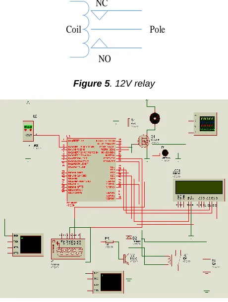
The hardware configuration of the control system is composed of LM35 sensor, microcontroller (PIC16F887), motor driver circuit, DC motor, LCD display, LED and relay. The LM35 sensor measure the temperature of the drill and then send to PIC16F887 to display on LCD and then the PIC send the temperature condition to host server via the client computer. PIC 16F887 is also used to drive the motor and control speed with PWM depending on the input from server. The outputs of microcontroller are LCD display, DC motor, relay and LED.
1. LM35 Sensor
LM35 can measure the temperature more accurately than thermistor and other sensor. And it generates a higher output voltage than thermocouples and may not require to amplify the output voltage. LM35 can measured temperature from -55°C to +150°C and operates from 4 to 30 volt and generates voltage of about 10mV/°C. In this
DC Motor
____________________
Nang Su Moan Hsam, Myo Maung Maung and Hla Myo Tun
1,2 Department of Electronic Engineering, Mandalay Technological University, Mandalay [email protected] ,
413 system, LM35 sensor is placed near the drill to measure the
tool temperature.
Figure 2. LM35 Sensor 2.12 V DC Motor
DC motor is used to running the drilling machine. The system used brushless DC motor because it is simpler than brushed motor. The speed of motor is controlled by microcontroller. The motor is supplied with 12V and IRFZ44N is used as an interface between the motor and the PIC. A 12V DC motor will operate down below 6V or up to over 15 or more. At a high voltage the speed & torque will be higher but the DC Motor upper voltage range is limited by rotational force & heat. The best way to lower a DC Motor speed is to use the Pulse Width Modulation (PWM) where full voltage is applied.
3. LCD Display
LCD displays utilize two sheets of polarizing material with a liquid crystal solution. A 16x2 alphanumeric LCD is used to display temperature state in this system.
Figure 3. 16 x 2 LCD display
4. Microcontroller
This system used PIC 16F887 microcontroller because its features make it ideal for more advanced level A/D applications in automotive, industrial, appliances or consumer applications. The whole system is controlled by PIC microcontroller. Figure 4 shows the pin of PIC 16F887 that used in this control system.
2
LM 35
PIC 16F887
Motor
17
LCD
To Client
25
26
Relay for water container
LED 30
29 19 20 21
22
27 28
Figure 4. Pin assignment of microcontroller
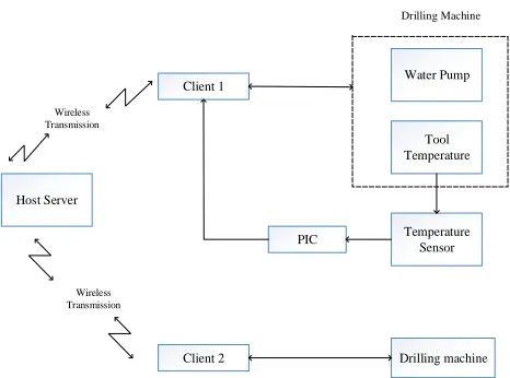
5. Relay
A relay is an electrically operated switch. Current flowing through the coil of the relay creates a magnetic field which attracts a lever and changes the switch contacts. The coil current can be on or off so relays have two switch positions and they are double throw (changeover) switches. In this system, the relay is used as a switch to open the pump motor of water container when the speed of motor is reduced. The relay is automatically off when the motor is running with normal speed again.
NC
NO
Pole Coil
Figure 5. 12V relay
Figure 6. Overall circuit diagram B. WIRELESS NETWORK DESIGN
414
Figure 7. Flowchart of the program based on WCF service
III. S
OFTWAREI
MPLEMENTATIONStart
Initialize Registers and I/O Ports
Drive Motor
Running Motor
Temperature>50°C
Reduce Speed and open water container
End
Display Temperature on LCD Sensing temperature from
LM35 for drill Get Input from
Server
Temperature>50°C
Display Temperature on LCD Send temperature condition to
server
Get command to reduce motor speed
from server No
Yes
No
Yes
Stop motor?
Yes No
Figure 8. Flowchart of PIC program
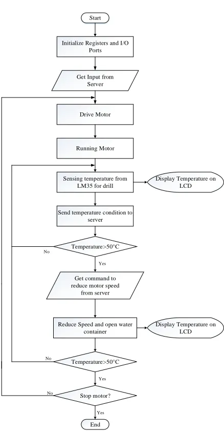
To implement the actual algorithm in the PIC16F887 microcontroller, the MikroC Pro complierwith debugger is used. To use this complier, we have to initialize and register the I/O ports before the run time module. The registers that need to initialize are watchdog timer, event manager and auxiliary register addressing. Figure 8 shows the flowchart of the algorithm for microcontroller. Frist, we have to initialize the required registers, I/O ports and LCD and get inputs from sensor and server. The temperature is display on LCD as soon as the motor is started running. The speed of motor is control with PWM signals. When temperature is over 50°C, ―overheat‖ display on LCD, LED is turned on and the controller at the server will send command to reduce the speed of motor. At that time, the relay turn on and the water container is opened for cooling drill. So, the temperature is gradually decrease. When the drill is cold and the temperature is decrease to about 45°C, the controller at the server send the command to run the motor with normal speed again. The server can also send command to stop the motor when the temperature is too high. PIC is also used as an interface between the client and the machine.
IV. S
IMULATIONR
ESULTSThe wireless control system for drilling machine is simulated in Proteus software. According to the components used in simulation, the prototype of drilling machine can be constructed. In real time, the PIC microcontroller is supplied with 5V and the DC motor is supplied with 12V. The relay is used as a switch for lubrication system. The following figures showthe simulation result for wireless control of drilling machine in Proteus software.
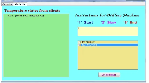
Figure 9. GUI design at host server when the temperature is less than 50°C
Figure 9 shows the GUI design at host server. The design used three instructions to control drilling machine, ―1‖ to start the motor, ―2‖ to slow the speed of motor and ―3‖ to stop motor. The controller must choose the IP address of the client that need to control. Figure 8 show the GUI design at the client. The client is connected with the drilling machine. The simulation of drilling machine is shown in Proteus software. Figure 11 shows the condition when thetemperature is lower than 50°C. The motor is running with normal speed. The LED does not turn on and the relay is in the original state. The relay is supplied with 12V and Start
Client=Null?
Binding IP of the client
Same network=?
Accept the client IP
Server and client can send message to each other
Client active=?
End NO
YES
YES NO
415 interface with PIC through 1N4001 diode and BC549
transistor.
Figure 10. GUI design at client when the temperature is lower than 50°C
Figure 11.Simulation result when the temperature is lower than 50°C
When the temperature is over 50°C, ―overheat‖ command is displayed on LCD, LED turn on at the machine and the controller at the server have to send the command ―2‖ to the machine to reduce the speed of motor. So, the motor running with PWM of half duty cycle as soon as it received ―2‖ from server. At that time, the relay is on and then the water pump system is start working.
Fig. 12 GUI design at host server when the temperature is over 50°C
Figure 13. GUI design at client when the temperature is over 50°C
Figure 14. Simulation result when the temperature is over 50°C
V. H
ARDWARER
ESULTSThe figure 15 show the hardware construction of wireless control system for drilling machine. The machine is connected to the client computer via RS 232 serial connection. It is connected to Rx and Tx pin of PIC microcontroller. The machine start running when it get command ―1‖ from server and change the speed when it get command ―2‖ and stop the motor from running when ―3‖ is received. Figure 15 show when ―2‖ is received from server and the motor is running. The temperature is over 50°C and the relay switch the pump motor for lubrication.
Figure 15. Prototype of drilling machine that connected with client computer
Client computer
Water container
416
V. C
ONCLUSIONWhen the drilling machine operates for a long time, the temperature increase and it can overheat. So, we need to control the speed of motor when the temperature increased and some lubrication system must be done for cooling the drill and work piece. This system control the speed of motor by the server. The server can control many machines simultaneously. Many machines can connect with clients in multi-clients system and control by host server. This system is mostly used in industries that need to reduce human worker and to control dangerous case of running machine without human worker.This control system can be used in any types of drilling machine. The overall circuit diagram for this control system is designed and constructed and water pump system is used for lubrication. This control system is effective and easy to implement in real time. And it is suitable for long running machines because speed control and lubrication system operate at the same time.The control system can be improved by following peripheral components used in the system with changing motor size or used diesel oil for lubrication system.
A
CKNOWLEDGMENTSThe author would like to thank to Dr. Hla Myo Tun, Associate Professor and Head of the Department of Electronic Engineering, Mandalay Technological University for his help. And thanks to all teachers from Department of Electronic Engineering, Mandalay Technological University for their guidance, support and encouragement.
REFERENCES
[1] ―Design and Simulation of Microcontroller BasedAutomatic Tool Changing System in CNCMachine‖, La Pyae Lynn, Theingi and Win Khaing Moe, World Academy of Science, Engineering and Technology, Vol:5 2011-09-25
[2] ―Drilling Machine General Information‖, Longwood University.
http://www.longwood.edu/assets/chemphys/ch4.pdf
[3] PIC 16FXXX Data Sheet, ―28/40/44-Pin, Enhanced Flash-Based 8-Bit CMOS Microcontrollers with nanoWatt Technology‖, pdf sheet.
[4] ―DCMotor‖, http://www.mpja.com/DCmotor/products/
[5] ―How Electronic Switches Work For Noobs: Relays and Transistors‖,
http://www.instructables.com/id/How-Electronic-Switches-Work-For-Noobs-Relays and/step3/Using-a-Relay/
[6] ―ADVANTAGES OF WCF OVER WEB SERVICES‖, Kola Siva Tharun, Muppalla Prudhvi, Satti Swami Reddy, International Journal of Computer Science and Mobile Computing, A Monthly Journal of Computer Science and Information Technology, IJCSMC, Vol. 2, Issue. 4, April 2013,pg.340–345
[7] Steve Resnick,Richard Crane and Chris Bowen,Essential Windows Commuincation Foundation
For .NET Framewok
3.5,Addison-wesley,Microsoft.NetDevelopmentSeries, Feb. 2008.