Design and Fabrication of Parabolic Trough Collector Using
Modified Evacuated Tube
HadiAshhar, Rahul Shrinivasan, Shubham Jaiprakash Tiwari, Wasim Ashraf, Zubair Sheikh
Mechanical Engineering, ACET, Nagpur, Maharashtra, India
ABSTRACT
An evacuated tube solar collector using therminol D-55 / Transformer oil as heat transfer fluid coupled with parabolic trough is studied in this paper. An experimental set-up is to be constructed to study the performance of evacuated tube collector with therminol D-55 / Transformer oil as heat transfer fluid. The parabolic trough is coupled with evacuated tube collector for better performance. In the traditional solar collectors water is used as heat transfer fluid. The problems in using water as heat transfer fluid are addressed in detail in this paper. The temperature characteristics of heat transfer fluid and water in the storage tank and the heating efficiency is to be determined under various conditions. The efficiency of therminol based evacuated tube collector coupled with parabolic trough is 40% more than that of water based evacuated tube collector coupled with parabolic trough. This study projects the potential of therminol based evacuated tube solar collector coupled with parabolic trough in the instant hot water generation. Also a copper coil is incorporated in the collector through which the water is passed. This setup will help in achieving higher temperature at the outlet thereby increasing the overall thermal efficiency of the PTC.
Keywords : PTC - Parabolic Trough Collector , SCM - Solar Collector Modules , SCA - Solar Collector Assembly
I.
INTRODUCTION
The evacuated tube is considered to be an important component in thermal application, particularly in solar water heating systems. The performance of evacuated tube solar parabolic collectors is better when compared to flat plate collector in high temperature applications. Different parameters like optical design, optimum operating conditions, heat transfer in tubes and performance studies of solar collectors have been studied by several researchers. Extracting heat from the evacuated tube is a major
difficulty in evacuated tube solar collector
applications. The fluid-in-glass and fluid-in-metal are the significant designs for better performance. Between the two, fluid-in-glass collector is widely used because of its low manufacturing cost and high thermal efficiency. Water is used as heat transfer fluid by many researchers. Morrison et al. studied the
natural circulation of heat transfer fluid in fluid-in-glass evacuated tubes experimentally and numerically. Fluid-in-glass evacuated tube cannot withstand high pressures and hence it is suitable for applications where few metres of water head is available.
studied by several researchers. Extracting heat from the evacuated tube is a major difficulty in evacuated tube solar collector applications. The fluid-in-glass and fluid-in-metal are the significant designs for better performance. Between the two, fluid-in-glass collector is widely used because of its low manufacturing cost and high thermal efficiency. Water is used as heat transfer fluid by many researchers. Fluid-in-glass evacuated tube cannot withstand high pressures and hence it is suitable for applications where few metres of water head is available.
1.1 Solar Energy
Solar energy is radiant light and heat from the Sun that is harnessed using a range of ever-evolving technologies such as solar heating, photovoltaics, solar thermal energy, solar architecture, molten salt power plants and artificial photosynthesis.
It is an important source of renewable energy and its technologies are broadly categorized as either passive solar or active solar depending on how they capture and distribute solar energy or convert it into solar power. Solar technologies are characterized as either passive or active depending on the way they capture, convert and distribute sunlight and enable solar energy to be harnessed at different levels around the world, mostly depending on distance from the equator.
Active solar techniques include the use
of photovoltaic systems, concentrated solar
power and solar water heating to harness the
energy.
Passive solar techniques include orienting a building to the Sun, selecting materials with favorable thermal mass or light-dispersing properties, and designing spaces that naturally circulate air.
Solar energy refers primarily to the use of solar radiation for practical ends, all renewable energies, other than Geothermal power and Tidal power, derive their energy either directly or indirectly from the Sun.
The Following are the advantages of using Solar energy -
1. Renewable Energy Source
Among all the benefits of solar panels, the most important thing is that solar energy is a truly renewable energy source. It can be harnessed in all areas of the world and is available every day. We cannot run out of solar energy, unlike some of the other sources of energy. Solar energy will be accessible as long as we have the sun, therefore sunlight will be available to us for at least 5 billion years when according to scientists the sun is going to die.
2. Reduces Electricity Bills
Since you will be meeting some of your energy needs with the electricity your solar system has generated, your energy bills will drop. How much will one save on their bill will be dependent on the size of the solar system and your electricity or heat usage. Moreover, not only will there be saving on the electricity bill, but if one generates more electricity than in use, the surplus will be exported back to the grid and bonus payments will be received for that amount (considering that your solar panel system is connected to the grid). Savings can further grow if one sells excess electricity at high rates during the day and then buy electricity from the grid during the evening when the rates are lower.
3. Diverse Applications
can also be integrated into the materials used for buildings. Not long ago Sharp introduced transparent solar energy windows.
4. Low Maintenance Costs
Solar energy systems generally don’t require a lot of maintenance. One needs to keep them relatively clean, so cleaning them a couple of times per year will do the job. Most reliable solar panel manufacturers give 20-25 years warranty. Also, as there are no moving parts, there is no wear and tear. The inverter is usually the
only part that needs to changed after 5-10 years
because it is continuously working to convert solar energy into electricity (solar PV) and heat (solar thermal). Apart from the inverter, the cables also need maintenance to ensure your solar power system runs at maximum efficiency. So, after covering the initial cost of the solar system, you can expect very little spending on maintenance and repair work.
5. Technology Development
Technology in the solar power industry is constantly advancing and improvements will intensify in the future. Innovations in quantum physics and
nanotechnology can potentially increase the
effectiveness of solar panels and double, or even triple, the electrical input of the solar power systems.
1.2 Solar Energy used as Thermal Energy
The Earth receives 174 petawatts (PW) of incoming solar radiation (insolation) at the upper atmosphere. Approximately 30% is reflected back to space while the rest is absorbed by clouds, oceans and land masses. The spectrum of solar light at the Earth's surface is mostly spread across the visible and
near-infrared ranges with a small part in the
near-ultraviolet. Most of the world's population live in
areas with insolation levels of 150–300 watts/m², or 3.5–7.0 kWh/m² per day. Solar radiation is absorbed by the Earth's land surface, oceans which cover about 71% of the globe –and atmosphere. Warm air containing evaporated water from the oceans rises,
causing atmospheric circulation or convection. When the air reaches a high altitude, where the temperature is low, water vapour condenses into clouds, which rain onto the Earth's surface, completing the water
cycle. The latent heat of water condensation amplifies
convection, producing atmospheric phenomena such as wind, cyclones and anti-cyclones. Sunlight absorbed by the oceans and land masses keeps the surface at an average temperature of 14 °C. By photosynthesis, green plants convert solar energy into chemically stored energy, which produces food, wood and the biomass from which fossil fuels are derived.
The total solar energy absorbed by Earth's atmosphere, oceans and land masses is approximately 3,850,000 (EJ) per year. In 2002, this was more energy in one hour than the world used in one year. Photosynthesis captures approximately 3,000 EJ per year in biomass.
The amount of solar energy reaching the surface of the planet is so vast that in one year it is about twice as much as will ever be obtained from all of the Earth's non-renewable resources of coal, oil, natural gas, and mined uranium combined. The potential solar energy that could be used by humans differs from the amount of solar energy present near the surface of the planet because factors such as geography, time variation, cloud cover, and the land available to humans limit the amount of solar energy that we can acquire.
1.3 Uses of Solar Energy
Solar energy can be converted to thermal (or heat) energy and used to:
Heat water – for use in homes, buildings, or swimming pools.
Heat spaces – inside greenhouses, homes, and
other buildings.
Solar energy can be converted to electricity in two ways:
Photovoltaic (PV devices) or ―solar cells‖ –
change sunlight directly into electricity. PV systems are often used in remote locations that are not connected to the electric grid. They are also used to power watches, calculators, and lighted road signs.
Solar Power Plants - indirectly generate
electricity when the heat from solar thermal collectors is used to heat a fluid which produces steam that is used to power generator.
1.4 Solar Thermal Heat and Solar Power Plants Solar thermal(heat) energy is often used for heating swimming pools, heating water used
in homes, and space heating of buildings. Solar space heating systems can be classified as
passive or active.
Passive space heating is what happens to your
car on a hot summer day. In buildings, the air is circulated past a solar heat surface(s) and through the building by convection (i.e. less dense warm air tends to rise while more dense cooler air moves downward) . No mechanical equipment is needed for passive solar heating.
Active heating systems require a collector to absorb and collect solar radiation. Fans or pumps are used to circulate the heated air or heat absorbing fluid. Active systems often include some type of energy storage system.
Solar collectors can be either non-concentrating or concentrating.
1) Non-concentrating collectors – have a collector area (i.e. the area that intercepts the
solar radiation) that is the same as the absorber area (i.e., the area absorbing the radiation). Flat Plate Collectors are the most common and are used when temperatures below about 200 degrees Fahrenheit are sufficient, such as for space heating.
2) Concentrating collectors – where the area intercepting the solar radiation is greater hundreds of times greater, than the absorber area.
Solar thermal power plants use the sun's rays to heat a fluid, from which heat transfer systems may be used to produce steam. The steam, in turn, is converted into mechanical energy in a turbine and into electricity from a conventional generator coupled to the turbine. Solar thermal power generation works essentially the same as generation from fossil fuels except that instead of using steam produced from the combustion of fossil fuels, the steam is produced by the heat collected from sunlight. Solar thermal technologies use concentrator systems due to the high temperatures needed to heat the fluid. The three main types of solar-thermal power systems are:
Parabolic trough – the most common type of
plant.
Solar dish
Solar power tower
II.
TECHNICAL SPECIFICATIONS
2.1 Parabolic Trough Collector-
where objects are positioned that are intended to be heated.A parabolic trough is made of a number of solar collector modules (SCM) fixed together to move as one solar collector assembly (SCA). A SCM could have a length up to 15 metres (49 ft) or more. About a dozen or more of SCM make each SCA up to 200 metres (660 ft) length. Each SCA is an independently-tracking parabolic trough.
A SCM may be made as a single-piece parabolic mirror or assembled with a number of smaller mirrors in parallel rows. Smaller modular mirrors requires smaller machines to build the mirror, reducing cost. Cost is also reduced in case of the need of replacing a damaged mirror. Such damage may occur due to being hit by an object during bad weather.The parabolic trough reflector can generate much high temperatures more efficiently than a single flat plate collector, since the absorber surface area is much smaller. The heat transfer fluid which is usually a mixture of water and other additives or thermal oil, is pumped through the tube and absorbs the solar heat reaching temperatures of over 200 0 C. The hot water is sent to a heat
exchanger where it directly heats a hot water storage tank for use in the home making this type of solar heating application a closed-loop active system. However, parabolic trough reflectors use only direct solar radiation to heat the receiver tube as diffused solar radiation cannot be focused onto the absorber making them less effective when the skies are cloudy or the sun is out of alignment.
To overcome this problem, most concentrating collectors require some form of mechanical equipment that constantly orients the collectors towards the sun keeping the heat pipe absorber at the correct focal point. This is achieved by using a Tracking Solar Concentrator that aligns the trough with the sun throughout the day, maximizing the solar heat gain.
The collector generally has a single rotation axis along the length of the trough which can be orientated in an
east-to-west direction, tracking the sun from north to south, or orientated in a north-to-south direction and tracking the sun from east to west. Parabolic troughs are generally aligned on a north-to-south axis, and are rotated to track the sun as it moves across the sky each day from morning to night. The advantages of this type of tracking mode is that very little collector adjustment is required during the day resulting in the
solar trough always facing the sun at noon time, but the collector performance early
in the morning or late in the afternoon is
greatly reduced due to the large incidence angles of the trough. Even though solar trough collectors use tracking systems to keep them facing the sun, they are most effective in sunnier climates where there are good solar resources. Like many other solar collectors, parabolic trough reflectors are modular, that is individual troughs can be connected together to give a larger surface area of absorber producing large amounts of solar hot water than can be created by an individual trough. Many single troughs connected together form a collector field were they are connected together in series and parallel rows.
PTCs focus direct solar radiation onto a focal line on the collector axis.
A receiver tube with a fluid flowing inside that absorbs concentrated solar energy from the tube walls and raises its enthalpy is installed in this focal line. The collector is provided with one-axis solar tracking to ensure that the solar beam falls parallel to its axis. PTCs can only use direct solar radiation, called beam radiation or Direct Normal Irradiance (DNI), i.e., the fraction of solar radiation which is not deviated by clouds, fumes or dust in the atmosphere and that reaches the Earth’s surface as a parallel beam.
―mirror‖ concentrates incident solar irradiation onto a much smaller receiver area, greatly decreasing heat loss and maximizing the available energy from the sun. One important factor in the analysis of solar concentrators is the concentration ratio. The concentration ratio is defined as the ratio of the area of the aperture of the concentrator to the area of the receiver that is reflected upon by the concentrator. This is in essence the heart of a solar concentrator. Solar tracking is also necessary for efficient use of concentrating collectors.
2.2 Evacuated Tube –
The Evacuated tube collector consists of a number of rows of parallel transparent glass tubes connected to a header pipe and which are used in place of the blackened heat absorbing plate we saw in the previous flat plate collector. These glass tubes are cylindrical in shape. Evacuated tube collectors do not heat the water directly within the tubes. Instead, air is removed or evacuated from the space between the two tubes, forming a vacuum (hence the name evacuated tubes). This vacuum acts as an insulator reducing any heat loss significantly to the surrounding atmosphere either through convection or radiation making the collector much more efficient than the internal insulating that flat plate collectors have to offer. With the assistance of this vacuum, evacuated tube collectors generally produce higher fluid temperatures than their flat plate counterparts so may become very hot in summer.
There are U-shaped copper pipes inserted in the evacuated tube with therminol—55 oil. The working fluid (in this case water) will be circulated in the copper pipes through a pump. The copper pipes will give the working fluid more time in the evacuated tube and also increases the thermal efficiency.
Inside the each glass tube, a flat or curved aluminium or copper fin is attached to a metal heat pipe running through the inner tube. The fin is covered with a
selective coating that transfers heat to the fluid that is circulating through the pipe. This sealed copper heat pipe transfers the solar heat via convection of its internal heat transfer fluid to a ―hot bulb‖ that indirectly heats a copper manifold within the header tank. These copper pipes are all connected to a common manifold which is then connected to a storage tank, thus heating the hot water during the day. The hot water can then be used at night or the next day due to the insulating properties of the tank.
Evacuated tube solar collectors are well suited to commercial and industrial hot water heating applications and can be an effective alternative to flat plate collectors for domestic space heating, especially in areas where it is often cloudy.
Evacuated tube collectors are overall more modern and more efficient compared to the standard flat plate collectors as they can extract the heat out of the air on a humid, dull overcast days and do not need direct sunlight to operate. Due to the vacuum inside the glass tube, the total efficiency in all areas is higher and there is a better performance even when the sun is not at an optimum angle. For these types of solar hot water panels, the configuration of the vacuum tube is what’s really important. There are a few different vacuum tube configurations, single wall tube, double wall tube, direct flow or heat pipe, and these differences can determine how the fluid is circulated around the solar hot water panel.
the hot water, to ensure the temperature and pressure levels never exceed a preset limit.
Also, heat pipe collectors should never be exposed to direct sunlight without a heat transfer fluid flowing through the heat exchanger. Doing so will cause the empty heat exchanger to become extremely hot and which may crack due to the sudden shock once cold water begins to flow through it.
Even though evacuated tube collectors are capable of heating water to +50 degrees Celsius in the winter, the outer glass tube of an evacuated tube does not heat up like a normal flat plate solar collectors when in use. This is due to the inherent insulation properties of the vacuum inside the tube which prevents the outer heat tube from being cooled by the outside ambient temperature which can be well below freezing.
Thus in the colder winter months, these types of collectors cannot melt away the large quantity of snow that falls on them at any one time which means clearing the snow and ice from the glass tubes daily can be a problem without breaking them.
Even if it is very snowy or very cold, enough sunlight will get through to keep the tubes well above freezing and still be able to preheat the water which can then be heated further by a standard electrical immersion heater or gas burner reducing the costs of heating the water in winter.
Evacuated Tube are a very efficient way of heating much of your hot water use just using the power of the sun. They can achieve high very temperatures but are more fragile than other types of solar collectors and are much more expensive to install. They can be used in either an active open-loop (without heat exchanger) or an active closed-loop (with heat exchanger) solar hot water system but a pump is required to circulate the heat transfer fluid from collector to storage in order to stop it from overheating.
2.3 Therminol-55 –
Therminol 55 is a synthetic heat transfer fluid used in moderate temperature applications. Therminol 55 fluid is designed for use in non-pressurized /low-pressure, indirect heating systems. It delivers efficient, dependable, uniform process heat with no need for high pressures. Therminol 55 has an optimum economic operating range of -25 °C to 290 °C (-15 °F to 550 °F). It can be used to an extended bulk temperature of 315 °C (600 °F). Therminol 55 fluid is designed for use in non-pressurized/ low-pressure indirect heating systems.
It delivers efficient, dependable, uniform process heat with no need for high pressures. The high boiling point of Therminol 55 helps reduce the volatility and fluid leakage problems associated with other fluids. While Therminol 55 has a relatively high flash point, it is not classified as a fire-resistant heat transfer fluid.
Therminol 55 has been shown to be significantly less sensitive than mineral oils to the negative consequences (sludging, fouling) of thermal oxidation. However, to further minimize the potential for fluid oxidation, systems utilizing heat transfer fluids should be blanketed with an inert atmosphere. A system pressure relief device should also be provided.
Therminol 55 can be utilized up to the extended maximum use temperature of 315 °C (600 °F). Actual fluid life is quite dependent on system design and operation. As fluid ages, the formation of volatile (low-boiling) products and high-boiling compounds may result.
Volatile products should be vented from the system to a non-hazardous area away from personnel and sources of ignition. The high-boiling compounds are generally soluble in the fluid. Overheating or fluid contamination will accelerate this decomposition and may result in separation of the high-boiling compounds as solids (tar, coke, etc.). These solids could be detrimental to the operation of the system and, when detected, should be removed
Figure Temperature variation of Therminol – 55 PERFORMANCE BENEFITS –
Long Life – You will get years of reliable, cost effective performance, even when operating your
system continuously at 290°C (550°F). This means you do not have to over specify your fluid.
Excellent resistance to fouling – Because Therminol 55 is a synthetic fluid, it resists the effects of oxidation 10 times better than mineral oils. Less oxidation and solids formation. For systems without nitrogen inerting, the performance advantages are significant.
Excellent Low Temperature Pumpability – Therminol 55 is still pumpable at -28°C (-18°F ), compared to some mineral oils that will not pump at temperatures below -7°C (20°F ). With Therminol 55, your heat transfer fluid system can start-up quickly and easily.
2.4 Use Of Copper Tube -
Copper has many desirable properties for thermally efficient. First and foremost, copper is an excellent conductor of heat. This means that copper's high thermal conductivity allows heat to pass through it quickly. Other desirable properties of copper include its corrosion resistance, biofouling resistance, maximum allowable stress and internal pressure, creep rupture strength, fatigue strength, hardness, thermal expansion, specific heat, antimicrobial properties, tensile strength, yield strength, high melting point, alloyability, ease of fabrication, and ease of joining.
Table 1. Thermal conductivity of some common metals
METAL THERMAL CONDUCTIVITY
(Btu/(hr-ft-F)) (w/(m-k))
Silver 247.87 429
Copper 231 399
Gold 183 316
Aluminium 136 235
Yellow brass 69.33 120
Cast iron 46.33 80.1
Innovation :
Water heats inside the evacuated tube via the vacuum interface between the the outside glass of tube and the inner blackened copper coil. As we know that water changes phase at 100 degree celcius and due to this phase change higher temperature is not achieved as the medium has both water vapour and water present at the same place. This results in reduction of overall
heat transfer to the fluid and this caused incomplete utilization of heat absorbed from solar energy.
In order to overcome this disadvantage, there are U-shaped copper pipes inserted in the evacuated tube with therminol—55 oil. The working fluid (in this case water) will be circulated in the copper pipes through a pump. The copper pipes will give the working fluid more time in the evacuated tube and also increases the thermal efficiency.
III.
EXPERIMENT SETUP
Design Calculations -
Equation of Parabola Y=0.041667 (in inches)
Focal point at in above origin
Length of parabola from X1 to X2 ,―S‖
p=12 t=2(6)=12
√
S=27.55in
Total length needed for sheet metal=27.55in Trough length 42in and radius 12in Length of evacuated tube = 18 metres
Thermal Calculations –
1. δ – Angle of Declination
2. Ws – The hour angle corresponding to sunset or sunrise
3. ̅ – monthly average of the sunshine per hour per day at location
4. ̅max – Monthly average of maximum possible sunshine per hour per day at location or
day length on a horizontal surface.
5 . - Latitude at which parabolic collector is being placed
6. Isc - The rate at which the energy is received from the sun on a unit area perpendicular to
the rays of the sun at the mean distance of the sun from the earth. 1. a1,b1 – constants obtained by fitting data .
2. El - Elevation of the location above mean sea level.
3. ̅0 – The monthly average of daily extraterrestrial radiation on horizontal surface at
Location.
4. ̅g – The monthly average of daily global radiation on a horizontal surface at a location.
a)Klen’s Equation -
Declination (δ) =23sin( +(284+n))
= -2.42
ws= cos-1 (-tan(latitude)* tan δ)
= cos-1(-0.387169*-0.042262)
= 90.93 0 = 1.5870 radians ̅max =
s = cos-1(-tan . tan δ)
= 12.12 hours
̅/ ̅max = 0.62
Therefore, ̅ = 7.6 hrs
̅0 = * Isc *(1+0.33(
))*wssin δ+cos cos δsinws
̅g/ ̅0 = 0.4774
Therefore, ̅g =16436.519 kJ/m2day
b) Gopinathan’s Equation –
a1 = - 0.309 + 0.539 cos - 0.0693 El + 0.290 ̅/ ̅max)
= - 0.309+ 0.539cos(21.16487) – 0.0693(0.31) + 0.290 (0.62) = 0.35956
b1 = 1.527 – 1.027 cos + 0.0926 El – 0.359 ( ̅/ ̅max)
= 1.527 – 1.027 cos(21.16487) + 0.0926 (0.31) +0.359 (0.62) = 0.375426
a1= 0.27 ; b1= 0.5 (page no.90, table 3.2)
̅g/ ̅0 = a+b ( ̅/ ̅max) (page no. 89)
= 0.27+0.5(0.62) = 0.58
Therefore, ̅g= 34429.24*(0.35956+0.375426(0.62))
= 20393.27 kJ/m2day
= 656 W/m2
Mass Flow Rate and Velocity of fluid :
Time taken to empty 1 litre Flask – 7 seconds Therefore mass flow rate = 1/7 = 0.143 litre/sec
Where ρ = Density of water in kg/m³ = 1000 kg/m³ Area of cross section of pipe = 0.00013 m²
V = Velocity of Fluid = in m/sec
Therefore m = ρ* A* V 0.143= 1000*0.00013*V => V = 1.1 m/s
Therefore, Velocity of Fluid in the evacuated tube is 1.1 m/s 7. Observations-
7.1 Temperature readings for the day March 15th using PTC with water as working fluid :
Table 2
Sr no. Time Inlet Temperature
(Celsius)
Outlet Temperature (Celsius)
1. 10:00 am 33 65
2. 11:00 am 65 80
3. 12:00 pm 80 91
4. 1:00 pm 91 92
5. 2:00 pm 92 87
6. 3:00 pm 87 85
7. 4:00pm 85 83
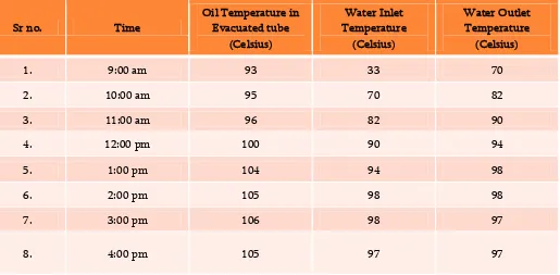
7.2 Temperature readings for the day March 16th using PTC with Therminol as working fluid :
Table 3
Sr no. Time
Oil Temperature in Evacuated tube
(Celsius)
Water Inlet Temperature
(Celsius)
Water Outlet Temperature
(Celsius)
1. 9:00 am 93 33 70
2. 10:00 am 95 70 82
3. 11:00 am 96 82 90
4. 12:00 pm 100 90 94
5. 1:00 pm 104 94 98
6. 2:00 pm 105 98 98
7. 3:00 pm 106 98 97
Thermal Efficiency : a) For March 15th –
h₁ = m*C*T₁
= 0.143*4.187*306 h₁ = 183.215 kJ/s h₂ = m*C*T₂
= 0.143*4.187*365 h₂ = 218.54 kJ/s
Q₁ = h₂ - h₁ =218.54 -183.215 => Q₁ = 35.33 kJ/s
b) For March 16th –
h₃ = m*C*T₃
= 0.143*4.187*306 h₃ = 183.215 kJ/s h₄ = m*C*T₄
= 0.143*4.187*371 h₄= 222.1329 kJ/s
Q₂ = h₄ - h₃ = 222.1329 – 183.215 => Q₂ = 39.91kJ/s
% increase in efficiency = (Q₂ - Q₁)/ Q₁ = (39.91 – 35.33)/35.33 = 0.1259 ≈ 13% Therefore increase in efficiency = 13%
Graphical Comparison Between the 2 Setups :
IV.
CONCLUSION
The main objective is to provide a product with an efficient way of heating water for various above mentioned applications for various industrial, rural and domestic uses. It has to be understood that in rural and upcoming new industries need an efficient