IJSRR, 8(1) Jan. –March, 2019 Page 405
Research article
Available online www.ijsrr.org
ISSN: 2279–0543
International Journal of Scientific Research and Reviews
Energy Efficient Hybrid Pervaporation / Distillation Process for
Ethanol - Water Separation
Doulat Nangare
1*and S. Mayadevi
2Department of Technology, Shivaji University, Kolhapur-416004
1
2
Retired Chief Scientist, CEPD Division, NCL, Pune- 411008
ABSTRACT
Increasing energy demand in the chemical process industry is one of the major factors for the
development of alternative separation processes to conventional separation processes. Compared to
conventional distillation, hybrid separation combining two or more unit operations may work out to
be energetically and economically more efficient in separations involving close boiling or azeotropic
composition. In this paper we demonstrate this using ethanol-water as the model system and
separation by Distillation -Pervaporation (D + PV) hybrid unit. Compared with azeotropic
distillation, pervaporation is more energy efficient when the feed ethanol concentration is high. 80 %
energy saving is possible using PV. At low feed ethanol concentrations, D + PV is more attractive
compared to only PV. 40 % energy can be saved as compared to PV. A method for the selection of
the number of trays of the distillation column is also discussed in this paper.
KEYWORDS:
Pervaporation, Hybrid Separation, Membrane, Azeotropic distillation, Vapor permeation*Corresponding author
Doulat Nangare
Department of Technology,
Shivaji University,
Kolhapur-416004
IJSRR, 8(1) Jan. –March, 2019 Page 406
INTRODUCTION
Distillation is a popular separation technology conventionally used for the separation of
liquid mixtures. One of the major drawbacks of conventional distillation is that, it is difficult to
separate the azeotropic or constant boiling mixtures. Pervaporation is one of the most promising
membrane technologies offering solution to dehydration of organic compounds, recovery of organic
compounds from aqueous solutions, separation of organic mixtures etc 1. Solution diffusion model is considered to be more suitable for describing transport through dense pervaporation membranes 2 Combined process consisting of distillation and pervaporation/vapor permeation offers economically
attractive alternatives as they can simplify the process structure, reduce the energy consumption and
avoid the entailers for the separation of azeotropes and close boiling solutions4,5,6. The simulation
of an existing plant revealed that 12% saving in the total annual cost could be achieved by using 32%
additional membrane surface 8.
In this paper we present Energy Efficient Hybrid Pervaporation / Distillation Process for
Ethanol - Water Separation. McCabe-Thiele method has been used for distillation tray calculations
while Rautenbach model based on solution diffusion theory has been used for pervaporation
calculations.
Model Development
Distillation model
A distillation unit comprising of column, total condenser and partial reboiler was considered
for the study. The model uses mass and energy balances at each tray, coupled with vapor liquid
equilibrium data. UNIQUAC and Virial equations of state have been used to generate the vapor liquid
equilibrium (VLE) of the mixture.
Pervaporation model
Among the diverse pervaporation models described in literature, the solution diffusion model
provides an accurate description of the behavior of membranes and the dependence of membrane
transport on pressure, concentration etc. and hence is widely used 9.
IJSRR, 8(1) Jan. –March, 2019 Page 407
solution–diffusion model used in this study, works with transport coefficient instead of diffusion
coefficient because its concentration dependence is considered negligible 10.
The molar flux of component k through the composite membrane can be calculated using Eq.(1)
𝐽
𝐾=
11+𝑄0𝑃𝐾0𝛾 𝐾𝐷 𝐾
.
𝐷 𝐾𝛾 𝐾
.
𝑃𝐾 1−𝑃𝐾 3
𝑃𝐾0 (1)
Where 𝐷𝐾 is the concentration independent transport coefficient of component k, 𝑄0 is
permeability of non supportive porous layer, 𝑃𝐾0 is vapor pressure of component at feed temperature,
PK1and PK3 are the partial pressure of component k in the feed and permeate respectively 𝛾 𝐾 is the
average activity coefficient of component k. For high water concentration azeotropes like is
obutanol–water separation, this equation needs modification13.
Pervaporation is strongly temperature dependent as can be seen in Eq. (2). Transport
coefficient depends on the temperature in an Arrhenius type exponential way.
𝐷
𝐾= 𝐷
∗
𝐾
exp
𝐸𝑅𝐾 𝑇1∗−
1
𝑇 (2)
𝐸
𝐾 represents the activation energy for component k and is associated with the transport coefficient,T* is the reference temperature, equal to 293 K. The activity coefficients are calculated with the
Wilson equation 13in this work, but can be calculated with other equation of state models as well. The Wilson parameters were derived from the database of Chemsep software.
A user friendly Visual Basic Simulation program (VBS) was developed, for PV and D+PV model
calculations. The VBS tool developed is capable of calculation of Number of Trays, minimum reflux
ratio, energy requirement for distillation column, membrane area, energy requirement for different
product specifications etc. PV calculations require pervaporation parameters like component diffusivities,
activation energies and permeance.
Experimental data reported by Lovasz and coworkers 11 has been used in this study for calculating the component flux through the membrane. Lovasz used commercial membrane PERVAP
2210 (by SULZER Chemtech GmBh) for pervaporation. Data reported for this membrane at 80 0C and
2.7 mbar permeate vacuum has been used in our work. PERVAP 2210 is hydrophilic PVA/PAN (0.5-2 micro meter thick PVA as perm selective and polyacrylonitrile as micro-porous support layer) membrane. The calculation flux was found to be in good agreement for higher ethanol concentration mixture with the
reported experimental data (Table I) 11.
Hybrid Separation Processes for Ethanol-water separation
Hybrid process configuration coupling membrane separation and distillation studied in current
IJSRR, 8(1) Jan. –March, 2019 Page 408 through a pervaporation unit. As the membrane is hydrophilic, water permeates through whereas ethanol
remains as the retentate. The bottom product of the distillation unit is predominantly water. Ethanol-water is conventionally separated by heterogeneous azeotropic distillation using n-pentane as entrainer.
Separation using Chemcad simulation tool is shown in Fig. The operating cost due to the introduction of the entrainer N-pentane and its subsequent separation and recycle in azeotropic separation process are
eliminated in the hybrid process.
RESULTS AND DISCUSSION
A comparison of azeotropic distillation and pervaporation for similar feed mixture (128.19
kmol.h-1, 85.6% (mol) ethanol) and product purity (103.48 kmol.h-1, 99.99% (mol) ethanol) has
been carried out initially. The azeotropic distillation, simulated using Chemcad simulator. The
reboiler energy input required is 12949 MJ.h-1 .
Pervaporation (PV) simulated with the VBS program, using PERVAP 22108 membrane is
compared with azeotropic distillation in Table II. For achieving similar product purity and output as
that of azeotropic distillation, PV requires only 1558 MJ.h-1 of energy (latent heat and energy for
vacuum generation). As no entrainer is used, there is no the requirement of its separation and recycle.
However, the process requires a PV unit with membrane area 867 m2.
Separation of dilute solutions by pervaporation is not economic due to large membrane
surface requirement. The calculations using VBS reveal that a single pervaporation unit of membrane
area 3221 m2 is required to produce 109.44 kmol.h-1 (99.99 % (mol) ethanol) from 548.89 kmol.h-1
(20 % (mol) ethanol) and the energy requirement is 37389 MJ.h-1. If hybrid separation (D + PV) is
used for same, energy requirement reduces to 22100 MJ.h-1. Distillation tower with 22 trays and
pervaporation unit with membrane area 841 m2 is sufficient to meet the requirement. Membrane area
is reduced by 74 % when hybrid separation (D + PV) is used for separation instead of just
pervaporation.
A comparison of the performance of a conventional distillation column and a D+PV hybrid
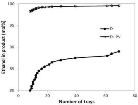
unit for the same feed ethanol concentration (20 % (mol)) is presented in Fig. II. For same number of
distillation column trays, product (ethanol mol %) in distillation process and hybrid process is
compared and The figure clearly illustrates the advantage of having a hybrid unit for the separation.
While the distillation tower composition cannot cross the azeotrope point due to thermodynamic
barrier, high purity ethanol can be obtained with a D+PV hybrid unit using a small distillation unit
IJSRR, 8(1) Jan. –March, 2019 Page 409
Optimum number of trays for Distillation column in hybrid unit
For the distillation of azeotropes in a conventional distillation unit without entrainer, the
number of trays required for distillation increases rapidly as the concentration approaches azeotrope
composition. This is depicted in Fig. III, where dt/dm is the incremental increase in the number of
distillation trays with incremental increase in the ethanol concentration at the distillation column
outlet and m the mole fraction of ethanol in the product. The figure shows that there is rapid increase
in the number of trays beyond an outlet ethanol concentration of 86.5 % (mol). So it becomes
important to judicially choose the number of trays in the distillation column of the D+PV hybrid unit.
The figure indicates that in D + PV hybrid separation unit, it is advantageous to introduce PV unit at
a tray composition of about 86 % (mol) instead of the azeotrope point (89.2 % (mol) ethanol).
Once the PV unit location is obtained from the dm/dt plot, it can be further refined by a
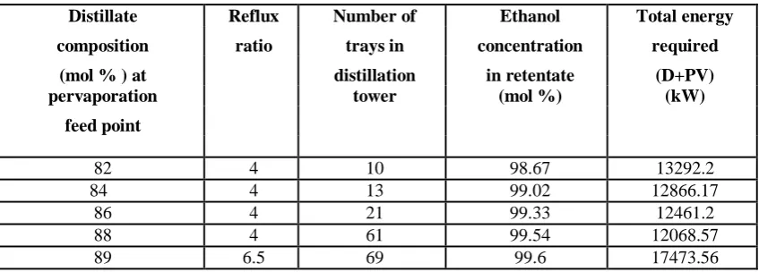
combination of the total energy requirement and the number of distillation trays. This is
demonstrated in Table III. As ethanol in the distillate increases from 84% to 89%, the number of
trays increases and the product composition from PV unit also increases. While the increase in
permeate composition is marginal, the increase in the number of trays is significant. There is a 3-fold
increase in the number of trays when the distillate composition is increased from 86 to 88 %. The
total energy requirement for the hybrid system deceases and passes through a minimum for the
distillate composition of 88%. However there is an inordinate increase in the number of trays when
the distillate composition is increased from 86 to 88 %. Hence the number optimum number of trays
of the Distillation unit is 21 and location of the PV unit is above tray no. 21
CONCLUSION
A comparison of conventional distillation unit, azeotropic distillation unit, pervaporation unit
and a hybrid separation unit comprising of distillation and pervaporation has been presented in this
paper. Ethanol-water binary separation has been chosen as the model system for the study. A Visual
Basic Simulation tool based on material and energy balance calculations and vapour-liquid
equilibrium data was used for distillation simulation while Rautenbach model based on
solution-diffusion theory has been used for pervaporation calculations. Chemcad software was used for
simulation of azeotropic distillation. For calculation of energy requirements, only the reboiler and
vacuum pump were considered. The material balance of ethanol for azeotropic distillation shows
that there is an overall loss of 5.74% ethanol per hour, whereas the corresponding loss in a
pervaporation unit with 867 m2 membrane area is less than 0.1%. The energy requirement for pervapoation is also considerably less. 80 % energy saving is possible in this case. While it is not
IJSRR, 8(1) Jan. –March, 2019 Page 410
tower, by attaching a PV unit after the condenser in conventional distillation, it is possible to obtain
very high purity ethanol as product. 40% energy can be saved using hybrid distillation/pervaporation
process.
REFERENCES
1. Jaimes, J. B., Alvarez, M. E. T., Rojas, J. V., & Maciel Filho, R. Pervaporation: Promissory
Method for the bioethanol separation of fermentation. Chem. Eng, 2014; 38.
2. Wijmans J G and Baker R W, The solution diffusion model: a review, J Membrane Science,
1995; 107: 1-21.
3. Baker R W, 2004. Membrane Technology and Applications, second ed. John Wiley & Sons.
4. Rom, A., Miltner, A., Wukovits, W., & Friedl, A. Energy saving potential of hybrid
membrane and distillation process in butanol purification: Experiments, modeling and
simulation. Chemical Engineering and Processing: Process Intensification, 2016; 104:
201-211.
5. Fontalvo, J., & Keurentjes, J. T. F. A hybrid distillation–pervaporation system in a single
unit for breaking distillation boundaries in multicomponent mixtures. Chemical Engineering
Research and Design, 2015; 99:158-164.
6. Kang, Q., Van der Bruggen, B., Dewil, R., Baeyens, J., & Tan, T. Hybrid operation of the
bio-ethanol fermentation. Separation and Purification Technology, 2015; 149: 322-330.
7. Servel C, Roizard D, Favre E and Horbez D, Improved Energy Efficiency of a Hybrid
Pervaporation/Distillation Process for Acetic Acid Production: Identification of Target
Membrane Performances by Simulation, Ind. Eng. Chem. Res. 2014; 53: 7768−7779.
8. Szitkai Z, Lelkes Z, Rev E, Fonyo Z, Optimization of hybrid ethanol dehydration systems,
Chemical Engineering and Processing 2002; 41: 631–646
9. Valentinyi N, Csefalvay E, Mizsey P, Modeling of pervaporation: Parameter Estimation and
model Development, Chemical Engineering Research and Design, 2013; 91: 174-183.
10.Valentínyi, N., & Mizsey, P. Comparison of pervaporation models with simulation of hybrid
separation processes. Periodica Polytechnica. Chemical Engineering, 2014; 58(1), 7.
11.Lovasz A, Mizsey P, Fonyo Z, Methodology for parameter estimation of modeling and
pervaporation in flow sheeting environment., Chemical Engineering Journal, 2007; 133:
219-227.
12.Lone, S., Ahmad, S. A., & Kumar, V. Modeling and Simulation of a Hybrid Process
IJSRR, 8(1) Jan. –March, 2019 Page 411
13.Treybal R E; Mass Transfer Operations (International Edition) McGraw Hill Inc. New York
1968.
14.Mahdi, T., Ahmad, A., Nasef, M. M., & Ripin, A. State-of-the-art technologies for separation
of azeotropic mixtures. Separation & Purification Reviews, 2015; 44(4): 308-330.
15.Nagy, E., Mizsey, P., Hancsók, J., Boldyryev, S., & Varbanov, P. Analysis of energy saving
by combination of distillation and pervaporation for biofuel production. Chemical
Engineering and Processing: Process Intensification, 2015; 98: 86-94.
Table No. I : Comparison of flux calculated using the VBS and Lovasz’s data8 for ethanol dehydration
usingPERVAP2210 at different feed ethanol concentrations: Water – Q0: 3.0 kmol. m-2h-1bar-1, DK*: 4.49*10-3
kmol. m-2 h-1, EK: 46165 kJ.kmol-1. Ethanol – Q0: 3.0 kmol. m-2h-1bar-1, DK*: 4.63*10-6 kmol. m-2 h-1, EK: 22614
kJ.kmol-1
Ethanol in Feed (mol %)
Permeate Flux (kmol.m-2 h-1)
Permeate Flux8
(kmol.m-2 h-1)
82 0.0272 0.03
75 0.04 0.042
70 0.0489 0.0475
Table No II :Comparison of azeotropic distillation and pervaporation for ethanol-water system: Feed128.19
kmol.h-1, 85.64 % (mol) ethanol; Product: 103.48 kmol.h-1, 99.99 % (mol) ethanol
Features Azeotropic distillation Pervaporation
No. of trays 19 -0-
Entrainer N-Pentane Nil Membrane area (m2) No membrane 867 Energy required (MJ.h-1) 12949.00 1558.24
Table III The effect of PV location on the energy requirement of the (D + PV) hybrid unit.
Membrane area used = 1400 m2
Distillate Reflux Number of Ethanol Total energy
composition ratio trays in concentration required
(mol % ) at distillation in retentate (D+PV)
pervaporation tower (mol %) (kW)
feed point
82 4 10 98.67 13292.2
84 4 13 99.02 12866.17
86 4 21 99.33 12461.2
88 4 61 99.54 12068.57
IJSRR, 8(1) Jan. –March, 2019 Page 412
Figure I: Configuration of a hybrid process coupling distillation and pervaporation (D+PV)
Figure II Comparison of the performance of a distillation unit and a D+PV hybrid unit for ethanol-water separation for a feed ethanol concentration of 20 % (mol)
Figure III: Incremental variations in the number of trays with incremental increase in outlet ethanol concentration (dt/dm) as a function of mole fraction ethanol (m) at the outlet in a distillation tower for the