RVC OPEN ACCESS REPOSITORY – COPYRIGHT NOTICE
This is the author’s accepted manuscript of the final article published in Nature. The version of record is available on the journal site: http://doi.org/10.1038/nature21727.
TITLE: Smart wing rotation and trailing-edge vortices enable high frequency mosquito flight
AUTHORS: Richard J. Bomphrey, Toshiyuki Nakata, Nathan Phillips, Simon M. Walker
JOURNAL TITLE: Nature
PUBLISHER: Nature Publishing Group
PUBLICATION DATE: 5 April 2017 (online)
Smart wing rotation and trailing-edge vortices enable high frequency mosquito
1
flight
2
Richard J. Bomphrey1*, Toshiyuki Nakata1,2, Nathan Phillips1, Simon M. Walker3
3
4
1Structure and Motion Laboratory, Royal Veterinary College, University of London, Hatfield, AL9
5
7TA. United Kingdom.
6
2Graduate School of Engineering, Chiba University, 1-33, Yayoi-cho, Inage-ku, Chiba-shi, Chiba
7
263-8522 Japan.
8
3Department of Zoology, University of Oxford, South Parks Road, Oxford, OX1 3PS.
9
*Correspondence to: rbomphrey@rvc.ac.uk
10
11
12
Summary
13
Mosquitoes exhibit unique wing kinematics; their long, slender wings flap at remarkably high
14
frequencies for their size (>800 Hz) and with lower stroke amplitudes than any other insect
15
group1. This shifts weight support away from the translation-dominated, aerodynamic
16
mechanisms used by most insects2, as well as by helicopters and aeroplanes, towards poorly
17
understood rotational mechanisms that occur when pitching at the end of each half-stroke.
18
Here we report wing kinematics and solve the full Navier-Stokes equations using computational
fluid dynamics with overset grids and validate our results with in vivo flow measurements. We
20
show that, while familiar separated flow patterns are used by mosquitoes, much of the
21
aerodynamic force that supports their weight is generated in a manner unlike any previously
22
described flying animal. In total, there are three key features: leading-edge vortices (a
well-23
known mechanism that appears to be almost ubiquitous in insect flight), trailing-edge vortices
24
caused by a novel form of wake capture at stroke reversal, and rotational drag. The two new
25
elements are largely independent of the wing velocity, instead relying on rapid changes in the
26
pitch angle (wing rotation) at the end of each half stroke, and are therefore relatively immune
27
to the shallow flapping amplitude. Moreover, these mechanisms are particularly well-suited to
28
high-aspect ratio mosquito wings.
29
Main Text
31
Mosquitoes disperse, find mates, lay eggs and seek hosts on the wing but their small size and
32
exceedingly high wing beat frequencies present a substantial challenge for biomechanical
33
measurements. To test our prediction that mosquitoes shift lift generation away from the
34
translational phase of the wingbeat and rely more heavily on the pitching rotation phases at the
35
end of each half stroke (Fig. 1), we measured the wing motion and simulated the resulting
36
aerodynamics of the southern house mosquito (Culex quinquefasciatus, Say; Supplementary
37
Video). We confirm that mosquitoes have a diminished reliance on leading-edge vortices, an
38
aerodynamic phenomenon that augments lift forces for insects3-8, birds9,10 and bats11 during
39
wing translation. The effect of leading edge vortices is to generate sufficient lift with smaller
40
wings; a clear advantage for flying taxa. Instead, we observed lift enhancement via two
41
mechanisms that are exclusive to mosquitoes thus far; i) lift enhancement due to a trailing-edge
42
vortex captured during stroke reversal and ii) partial weight support due to a newly-described
43
rotational effect at the end of each half stroke. The latter mechanism, rotational drag, has been
44
postulated previously12,13 but, here, is mediated by exquisitely-timed kinematic patterns that
45
cause a leading-to-trailing edge shift of the pitching axis during stroke reversal.
46
Our analysis of the free-flight kinematics of male Culex mosquitoes (Fig. 1A-C) revealed that
47
they flapped their wings at frequencies of 717 ± 59 (mean ± one s.d.) Hz and with amplitudes of
48
just 39°±4°, which is by far the smallest amplitude yet measured for any hovering animal,
49
despite operating at similar scales to fruit flies (Fig. 1D). The stereotypically low amplitudes we
50
measured mean that the 75% radial position of the wing travels just two chord lengths between
stroke reversals. This, in turn, causes substantial aerodynamic consequences and the
52
breakdown of the fluid mechanics assumption that wings act like sweeping helicopter blades14.
53
Our simulations of forces, torques, power expenditure and flow fields show great consistency,
54
with the aerodynamic features being entirely robust to the wide variety of body velocities and
55
wing kinematics within the behavioural repertoire we measured (Extended Data Figure 1). We
56
re-validated the CFD solver using particle image velocimetry and the corresponding flow fields
57
matched both qualitatively and quantitatively (Fig. 2).
58
The three distinct aerodynamic mechanisms occur sequentially during the stoke cycle, each
59
used on both the downstroke and the upstroke: the trailing-edge vortex due to wake capture,
60
the leading-edge vortex, and rotational drag. We present one mosquito by way of example
61
(M08; Fig. 1), although every mosquito we measured exhibited each of these aerodynamic
62
mechanisms (Extended Data Figures 2-6). Five key instants, marked t1-t5, are highlighted on the
63
aerodynamic force traces (Fig. 3A). The first key instant (t1) corresponds to a peak in lift force
64
early in the downstroke, shortly after pronation, (Fig. 3A, t1) due to a strong trailing-edge
65
vortex bound to the hind portion of the wing (Fig. 3F). The trailing-edge vortex forms as the
66
high-velocity induced flow from the preceding upstroke separates as it encounters the trailing
67
edge at a higher angle of attack than in other insects (Extended Data Figure 7). The trailing edge
68
has very low ground speed at this moment but, under the influence of the upstroke wake, the
69
airspeed and pressure gradient are sufficient for the shear layer to roll up into a coherent
70
attached vortex. As it does so, a region of intense negative pressure forms that contributes to
71
weight support.
The trailing-edge vortex is a form of wake capture as it is dependent on flow induced during the
73
previous half stroke. However, it is fundamentally distinct from previously described wake
74
capture effects because a wake structure forms as the flow first encounters the trailing edge of
75
the wing. This contrasts with the simpler case of augmentation or reorientation of lift
76
generated by a forward translating wing. The resultant flow pattern is strikingly reminiscent of
77
the leading-edge vortex pattern seen previously, but it is reversed. Instead, the flow separates
78
at the trailing edge, with streamlines reattaching further forwards along the wing chord,
79
enveloping a coherent attached vortex (Fig. 3F, t1). It is also distinct from previous descriptions
80
of a starting vortex (sometimes referred to as a trailing-edge vortex) because it is both bound to
81
the wing surface, rather than left in the wake, and makes a positive contribution to weight
82
support. This transient trailing-edge vortex is quickly shed into the wake as the wing accelerates
83
into the short translational phase, giving way to a leading-edge vortex (Fig. 3G) and a
84
corresponding second peak in lift (Fig. 3, t2).
85
A third peak in lift occurs due to rapid supination during the onset of stroke reversal at the end
86
of the downstroke (Fig. 3, t3). The mechanism for this is the recently-described phenomenon of
87
rotational drag 12. The wing rotates initially around an axis close to the leading edge, resulting in
88
strong forces normal to the posterior wing surface. The signature of this effect is an intense
89
negative pressure appears, again, in the region of the trailing edge. We can differentiate
90
between lift due to rotational drag12,13 and rotational lift15,16 because the aerodynamic force
91
vector is normal to the wing surface despite negligible translational velocity of the wing. As the
92
wing decelerates (t/T=0.5), rotational drag makes a reduced contribution to weight support,
becoming zero on the point of stroke reversal and even making a small negative impact in some
94
cases (Extended Data Figure 8).
95
On the upstroke, the wing is inverted and the processes are repeated. As such, the fourth key
96
instant (t4) corresponds to a new trailing-edge vortex (Fig. 3I) that quickly gives way to another
97
leading-edge vortex (Fig. 3J). The peak in lift force during the late upstroke (t5) is a combination
98
of the leading-edge vortex influence as the wing translates, and also rotational drag, because
99
wing rotation begins earlier in the upstroke than downstroke (Fig. 1C). The mechanisms are
100
additive and it is striking that peak force generation happens this late in the wing beat cycle.
101
This contrasts with most other animals, with the exception of fruit flies17,18, which exhibit
102
maximal forces during the downstroke. High upstroke loads for mosquitoes will have
103
consequences for the mechanical stresses on the wing, which may in turn predicate differences
104
in anatomical architecture such as wing camber or vein cross-section profiles.
105
Quasi-steady modeling has been an important tool for aerodynamicists but it cannot
106
encapsulate wake capture, rotational drag and non-linear vortex phenomena. We produced a
107
quasi-steady model which used dynamic force coefficients based on lift and drag polars at four
108
Reynolds numbers (Extended Data Figure 9) to highlight which wing stroke forces are the result
109
of unconventional mechanisms and will consequently be explained poorly by a quasi-steady
110
model. As expected, the key instants described above–where extra lift is generated through
111
rotational mechanisms–revealed a marked underestimate of the lift calculated from CFD
112
simulations, with a further discrepancy noted as the lift due to rotational drag becomes
113
negative at supination (Fig. 3B). To investigate further the relative importance of aerodynamic
114
phenomena at wing rotation, we simulated the flow fields generated by larger amplitude wing
strokes while maintaining the mean wing tip speed using CFD. This process shifts the balance of
116
force generation back towards conventional, translational aerodynamics and diminishes the
117
relative contribution of the rotational phases. The effect is demonstrated clearly by the
118
increasing discrepancy at instances t1, t3 and t5 (Fig. 3E).
119
Leading-edge vortices on the up- and downstrokes produce large regions of negative pressure
120
close to the leading edge of the wing (Fig. 3G,J); however, these are interleaved with
trailing-121
edge vortices and rotational drag effects that principally act on the posterior region, leading to
122
chord-wise fluctuations in the centre of pressure. The key instants t1 (trailing-edge vortex), t3
123
(rotational drag) and t4 (upstroke trailing-edge vortex) show the dominance of the trailing
124
portion of the wing in lift support, whereas t2 (the downstroke leading-edge vortex) shows the
125
leading edge as dominant. In the case of t5, the leading-edge vortex during the upstroke has
126
grown large enough to encroach into the aft portion of the wing and rotational drag is
127
beginning to take effect so the differential is negligible. Consequently, the wing undergoes
128
fluctuations in the pitching torque, with the location of the centre of pressure sometimes acting
129
in concert with the pitching of wing (Fig. 3C; e.g. t1 and t4), resulting in a low power
130
requirement that suggests passive pitching through aeroelastic effects (Fig. 3D).
131
Crucial to the mosquito’s ability to generate forces large enough to support its weight in flight is
132
the high angular rate and exquisite timing of stroke reversal. Lift due to rotational drag is
133
proportional to the square of the pitching angular rate, but equally important is the precise axis
134
of rotation. In mosquitoes, the pitching rotational axis of the wing moves from leading to
135
trailing edge during pronation at the end of the upstroke (Fig. 4A). By rotating first around an
136
axis close to the leading edge, low pressure develops close to the trailing edge, creating a
component of aerodynamic force that supports the mosquito’s weight and drawing the
leading-138
edge vortex towards the trailing edge. If this rotational axis were maintained throughout
139
pronation, the lift due to rotational drag would become negative as the wing angle passed
140
through vertical. However, by shifting the axis of rotation progressively towards the trailing
141
edge as the wing rotates, the new aerodynamic upper surface of the wing develops a region of
142
negative pressure close to the leading edge. This region contributes positively to weight
143
support through rotational drag at the start of the new half stroke but also initiates flow
144
separation for the new leading-edge vortex to form and grow during the downstroke (t2). At
145
the end of the downstroke, the leading-edge vortex migrates toward the trailing edge and acts
146
to initiate the trailing-edge vortex after supination. The trailing-edge vortex phenomenon is a
147
wake capture event during stroke reversal – when the wing is translating slowly – so the
148
mechanical work done by the flight motor is very low, and lift efficiency is consequently
149
relatively high at this instant (Fig. 3D, t1). Immediately after the wing passes through the
150
vertical alignment, the aerodynamic torque on the wing provided by the captured trailing-edge
151
vortex acts to pitch the wing passively in preparation for the next sweep.
152
The great benefit of lift mediated by rotational drag is that the aerodynamic force (in contrast
153
to conventional lift from a sweeping wing) is independent of radial position. It is therefore
154
equally effective along the entire wing span, even in the portion of the wing close to the root
155
where velocity due to the sweep of the wing – and hence lift due to translation – is near zero.
156
This feature, in combination with reduced inertial costs during rotation and smaller pitching
157
torques due to reduced moment arm length, is likely to be a key factor in shaping the high
158
aspect ratio wings of mosquitoes. We do not necessarily expect these aerodynamic features to
be unique to mosquitoes, but the trailing-edge vortex wake capture mechanism is not a
160
significant feature of fruit fly flight, despite operating at similar Reynolds numbers (Fig. 4B-C). It
161
remains an open question as to why mosquitoes have evolved to operate far outside the usual
162
bounds of kinematic patterns used by other insects. Given that high frequency flapping will
163
undoubtedly incur greater inertial power requirements, one can presume compensatory
164
selective advantages, perhaps in the domain of acoustic communication19.
165
166
167
Methods
168
Mosquitoes. Culex quinquefasciatus ‘Muheza’ strain, originally sourced from the London
169
School of Hygiene and Tropical Medicine, were bred at the University of Sussex and tested at
170
the Royal Veterinary College, London. Groups were maintained in microclimate chambers with
171
controlled humidity (70-75%), temperature (26±2°C) and 12:12 h light cycles. Males between 4
172
and 14 days post-emergence were tested in groups of four to eight individuals.
173
Kinematics acquisition. Mosquito wing kinematics were measured using the apparatus
174
illustrated in Extended Data Figure 1a-b, comprised of eight high-speed cameras (Photron SA3:
175
384 × 352 px, Photron Ltd) operating at 10,000 fps with an exposure time of 5μs. Each camera
176
was fitted with a 180 mm macro lenses set at f=16. Consistent backlighting for each camera was
177
provided by a co-axial, high-power infrared LED with divergent and Fresnel lenses to collimate
178
the light in paths of approximately 25 mm diameter. The cameras were arranged such that they
179
viewed a common volume of approximately 20 × 20 × 20 mm at the centre of a transparent flight
arena measuring 330 × 330 × 230 mm. In total, we processed 425 wing beats, over 15 sequences
181
from between 12 and 15 individuals, discernable by their wing length (Extended Data Figure 1c).
182
Kinematics reconstruction. The eight cameras were calibrated using custom-written, bundle
183
adjustment software running in Matlab (MATLAB, The Mathworks Inc.), which provides
184
estimates of the intrinsic and extrinsic camera parameters, while simultaneously calculating the
185
spatial coordinates of points on a 2D calibration grid in a series of positions and orientations20.
186
We selected 15 sequences for kinematic analysis Extended Data Figure 1d), which included all
187
sequences where both wings were visible in seven or more camera views for a minimum of eight
188
wingbeats. Four points on the body were manually registered in three camera views; the base of
189
the proboscis, the tip of the abdomen, and the left and right wing roots. These points were used
190
to calculate the 3D position and orientation of the mosquito body for each frame. A fully
191
automated shape-carving method was used to reconstruct the coordinates of the wing outline21.
192
The wing outline was first identified in each camera view using standard image processing tools
193
in Matlab (Fig. 1B). The shape-carving algorithm then identified voxels corresponding to the
194
wing outlines when projected onto each camera plane.
195
The wingtip position was determined by finding the voxels along the wing outline that were
196
furthest from the wing root. Voxels corresponding to the leading and trailing edges of the wing
197
were then separated using k-means clustering and a cubic spline fitting to each edge from the
198
wing base to the wingtip. The spanwise variation in pitch angle, α, was summarised by
199
regressing the angle between the leading and trailing edge of the wing against spanwise distance
200
along the wing, to give a pitch offset and linear twist gradient.
201
Computational fluid Dynamics (CFD). The morphological model for CFD analyses was
202
constructed by digitizing the wing outline from microscope images of excised wings and fitting
ellipses to the body in the raw video images. Assuming a low leakiness of hairs at the anterior
204
margin due to the ultra-low Reynolds number22, we used outlines incorporating the hairs as part
205
of the wing shape. The mean shape of three individuals (Extended Data Figure 10a; red lines)
206
was used for the surface mesh (Extended Data Figure 10b). Uniform thickness was assumed as 1
207
% of mean chord length with elliptic smoothing at the leading and trailing edges as well as the
208
wing tip and base. The body surface was extracted by manually fitting a series of ellipses to the
209
body in each camera view. Each ellipse was normal to the central axis of the body, which was
210
determined separately using the positions of head and body landmarks. The ellipses were then
211
interpolated by cubic splines and used to generate the mesh surface shown in Extended Data
212
Figure 10c-d.
213
For our CFD model, we used a dynamic flight simulator23,24 that is based on the incompressible,
214
unsteady three-dimensional Navier-Stokes equations and can easily integrate the realistic
215
morphology, kinematics and aerodynamics of insect flight. The simulator utilizes a multi-block,
216
overset-grid method in which the computational domain is decomposed into the local grid,
217
clustered near the wings and body, and a global Cartesian grid. The wing and body grids in
218
Extended Data Figure 10e were generated from the surface mesh. The minimum grid spacing
219
from surface is defined based on 0.1/sqrt(Re). The distance between the surface and outer
220
boundary is set to be 2.0 cm (mean chord lengths) for wing and 1.0 cm for body grids. The outer
221
boundary conditions for local grids are given by a Cartesian background grid (28R × 14R × 28R;
222
Extended Data Figure 10f). We assumed a symmetric motion of the left and right wings, and
223
applied a symmetric boundary condition at the sagittal plane of the body and background grid.
224
The wing grid was regenerated every time-step after twisting the wing surface, and rotated
225
around wing base. The flapping angles were interpolated by a fifth order Fourier series.
Self-consistency was tested by four CFD cases with coarse, fine and finer grids, and a reduced
227
time-step interval, dt. The time-series data of vertical force, mean aerodynamic force and power
228
are summarized in Extended Data Figure 10g. While there is a slight difference in the coarse
229
case, there is no large discrepancy observed among the other cases. Two time steps (comparing
230
fine and fine dt) also show little difference. Therefore, the grids for fine case with dt=0.01 was
231
used for all subsequent simulations.
232
Particle Image Velocimetry (PIV). Mosquitoes were placed in the centre of a clear tank (380 ×
233
140 × 300 mm) by a thin wire attached to the dorsal side of the thorax using cyanoacrylate glue.
234
The tank was seeded with a mist of olive oil droplets of approximately 1µm diameter, generated
235
by a compressed air seeding generator (LaVision UK Ltd, UK), and the flow was left for a few
236
minutes to become quiescent. The seeding particles were illuminated using a 10 mJ dual-cavity
237
pulsed laser (Litron LDY-301PIV, ND: YLF, 527 nm, Litron Lasers Ltd, UK). The beam
238
diverged into a sheet of approximately 1mm thickness after passing through a -20 mm cylindrical
239
lens, entering the flight arena from above such that the sheet was parallel with the sagittal plane
240
of the mosquito, incident with the wing half way from root to tip (R = 0.5). Images were
241
captured over a sampling area of 17 × 17 mm around the wing using a single high-speed camera
242
(Photron SA3: 2000 fps, 1024 × 1024 px, Photron Ltd) fitted with a 180 mm macro lens
243
(Tamron) whose axis was normal to the light sheet.
244
The camera and laser were driven using DAVIS v.7.2.2 software and synchronized by a
high-245
speed controller (LaVision UK, Ltd) operating at a rate of 1000 image pairs per second. The
246
system was post-triggered by a TTL signal and each recording captured 1361 image pairs
247
(limited by camera buffer capacity). The camera was calibrated using a custom calibration plate
(circle diameter =1 mm; circle separation dx=2 mm) and the calibration procedure in Davis
249
v.7.2.2.
250
Raw images were pre-processed by subtraction of a sliding background (2 px) and particle
251
intensity normalization (min/max-filter, 10 px) to remove any stationary elements in the images
252
(e.g. reflection from body, legs and antenna). The reflection from the wing is masked manually
253
for presentation. After filtering, the images were cross-correlated to calculate fluid vector fields
254
by multi-path correlation with a decreasing interrogation window size from 64 x 64 (50%
255
overlap) to 16 x 16 (50 % overlap). PIV calculations were performed using Davis v.8.1.5
256
(LaVision UK, Ltd). Post processing of vector fields involved filling up of empty spaces by
257
interpolation and a 3 x 3 smoothing. We selected the frames before the mosquito began to
258
respond to the laser light (approximately the first 50 frames in a sequence) with relatively low
259
glare on wing.
260
Blade element model with quasi-steady assumption. In order to highlight the unconventional
261
aerodynamics of hovering mosquitoes, we have compared the forces from the CFD simulations
262
with a blade element model with the quasi-steady assumption that takes into account the
263
translational circulation and drag, and added mass12,25. The lift and drag force coefficients, C L
264
and CD, were calculated using the mean lift and drag from a separate CFD analysis simulating a
265
spinning mosquito wing model. We used the 3rd cycle (1080°-1170°) to account for the effect of
266
induced downwash from previous strokes. As we found a strong dependency of force
267
coefficients profile on Reynolds number (50-300), CL and CD in the blade element model were
268
interpolated by a 2D spline, assuming those as the functions of angle of attack and instantaneous
269
Reynolds number based on mean chord length and instantaneous wing tip velocity. The range of
270
Reynolds number for CL and CD covers the maximum instantaneous Reynolds number of Culex
mosquitoes, 250, and the CL and CD at Re=50 (the 20th percentile of instantaneous Reynolds
272
number) was used if the instantaneous Reynolds number dropped to a value lower than 50.
273
274
Data availability statement. Datasets underpinning the current study are available in the Dryad
275
repository [doi:10.5061/dryad.tc29h].
276
277
Code availability. The CFD solver23 and kinematics acquisition code20,21 are described in further
278
detail elsewhere.
279
References
282
283
1 Simões, P. M. V., Ingham, R. A., Gibson, G. & Russell, I. J. A role for acoustic distortion in novel rapid 284
frequency modulation behaviour in free-flying male mosquitoes. Journal of Experimental Biology, 285
doi:10.1242/jeb.135293 (2016). 286
2 Chin, D. D. & Lentink, D. Flapping wing aerodynamics: from insects to vertebrates. Journal of
287
Experimental Biology219, 920-932, doi:10.1242/jeb.042317 (2016). 288
3 Ellington, C. P., van den Berg, C., Willmott, A. P. & Thomas, A. L. R. Leading-edge vortices in insect 289
flight. Nature384, 626-630 (1996). 290
4 Somps, C. & Luttges, M. Dragonfly Flight - Novel Uses of Unsteady Separated Flows. Science228, 1326-291
1329 (1985). 292
5 Bomphrey, R. J., Srygley, R. B., Taylor, G. K., Nudds, R. L. & Thomas, A. L. R. Visualising the flow 293
around insect wings. Phys. Fluids14, S4 (2002). 294
6 Thomas, A. L. R., Taylor, G. K., Srygley, R. B., Nudds, R. L. & Bomphrey, R. J. Dragonfly flight: free-295
flight and tethered flow visualizations reveal a diverse array of unsteady lift-generating mechanisms, 296
controlled primarily via angle of attack. Journal of Experimental Biology207, 4299-4323, 297
doi:10.1242/jeb.01262 (2004). 298
7 Bomphrey, R. J., Taylor, G. K. & Thomas, A. L. R. Smoke visualization of free-flying bumblebees 299
indicates independent leading-edge vortices on each wing pair. Experiments in Fluids46, 811-821, 300
doi:10.1007/s00348-009-0631-8 (2009). 301
8 Srygley, R. B. & Thomas, A. L. R. Unconventional lift-generating mechanisms in free-flying butterflies. 302
Nature420, 660-664, doi:10.1038/nature01223 (2002). 303
9 Videler, J. J., Stamhuis, E. J. & Povel, G. D. E. Leading-edge vortex lifts swifts. Science306, 1960-1962 304
(2004). 305
10 Warrick, D. R., Tobalske, B. W. & Powers, D. R. Aerodynamics of the hovering hummingbird. Nature
306
435, 1094-1097, doi:10.1038/nature03647 (2005). 307
11 Hedenstrom, A. et al. Bat flight generates complex aerodynamic tracks. Science316, 894-897, 308
doi:10.1126/science.1142281 (2007). 309
12 Nakata, T., Liu, H. & Bomphrey, R. J. A CFD-informed quasi-steady model of flapping-wing 310
aerodynamics. J. Fluid Mech.783, 323-343, doi:10.1017/jfm.2015.537 (2015). 311
13 Whitney, J. P. & Wood, R. J. Aeromechanics of passive rotation in flapping flight. J. Fluid Mech.660, 312
197-220, doi:doi:10.1017/S002211201000265X (2010). 313
14 Ellington, C. P. The aerodynamics of hovering insect flight. V. A vortex theory. Phil. Trans. R. Soc. Lond.
314
B305, 115-144 (1984). 315
15 Dickinson, M. H., Lehmann, F.-O. & Sane, S. P. Wing rotation and the aerodynamic basis of insect flight. 316
Science284, 1954-1960 (1999). 317
16 Sane, S. P. & Dickinson, M. H. The aerodynamic effects of wing rotation and a revised quasi-steady model 318
of flapping flight. Journal of Experimental Biology205, 1087-1096 (2002). 319
17 Aono, H., Liang, F. & Liu, H. Near- and far-field aerodynamics in insect hovering flight: an integrated 320
computational study. Journal of Experimental Biology211, 239-257, doi:10.1242/jeb.008649 (2008). 321
18 Fry, S. N., Sayaman, R. & Dickinson, M. H. The aerodynamics of hovering flight in Drosophila. Journal of
322
Experimental Biology208, 2303-2318, doi:10.1242/jeb.01612 (2005). 323
19 Cator, L. J., Arthur, B. J., Harrington, L. C. & Hoy, R. R. Harmonic convergence in the love songs of the 324
dengue vector mosquito. Science323, 1077-1079, doi:10.1126/science.1166541 (2009). 325
20 Walker, S. M., Thomas, A. L. R. & Taylor, G. K. Photogrammetric reconstruction of high-resolution 326
surface topographies and deformable wing kinematics of tethered locusts and free-flying hoverflies. 327
Journal of The Royal Society Interface, doi:10.1098/rsif.2008.0245 (2008). 328
21 Walker, S. M., Thomas, A. L. R. & Taylor, G. K. Operation of the alula as an indicator of gear change in 329
hoverflies. Journal of The Royal Society Interface, doi:10.1098/rsif.2011.0617 (2011). 330
22 Cheer, A. Y. L. & Koehl, M. A. R. Paddles and rakes - fluid-flow through bristled appendages of small 331
organisms. J. Theor. Biol.129, 17-39, doi:10.1016/s0022-5193(87)80201-1 (1987). 332
23 Liu, H. Integrated modeling of insect flight: From morphology, kinematics to aerodynamics. J. Comput.
333
24 Nakata, T. & Liu, H. A fluid-structure interaction model of insect flight with flexible wings. J. Comput.
335
Phys.231, 1822-1847, doi:10.1016/j.jcp.2011.11.005 (2012). 336
25 Berman, G. J. & Wang, Z. J. Energy-minimizing kinematics in hovering insect flight. J. Fluid Mech.582, 337
153-168, doi:10.1017/s0022112007006209 (2007). 338
26 Altshuler, D. L., Dickson, W. B., Vance, J. T., Roberts, S. P. & Dickinson, M. H. Short-amplitude high-339
frequency wing strokes determine the aerodynamics of honeybee flight. Proc. Natl. Acad. Sci. U. S. A.102, 340
18213-18218, doi:10.1073/pnas.0506590102 (2005). 341
27 Willmott, A. P. & Ellington, C. P. The mechanics of flight in the hawkmoth Manduca sexta I. Kinematics 342
of hovering and forward flight. Journal of Experimental Biology200, 2705-2722 (1997). 343
28 Vance, J. T. & Roberts, S. P. The effects of artificial wing wear on the flight capacity of the honey bee Apis 344
mellifera. Journal of Insect Physiology65, 27-36, doi:http://dx.doi.org/10.1016/j.jinsphys.2014.04.003 345
(2014). 346
29 Phillips, N., Knowles, K. & Bomphrey, R. J. The effect of aspect ratio on the leading-edge vortex over an 347
insect-like flapping wing. Bioinspiration & Biomimetics10, 056020 (2015). 348
349
Acknowledgments
351
The authors were supported by the EPSRC (EP/H004025/1), BBSRC (BB/J001244/1). RJB was
352
supported by an EPSRC Career Acceleration Fellowship. SMW was supported by a Royal
353
Society University Research Fellowship. The work reported in this paper was funded by the
354
Autonomous Systems Underpinning Research (ASUR) programme under the auspices of the
355
Defence Science and Technology Laboratory (Dstl), UK Ministry of Defence. The authors
356
acknowledge useful discussions with Prof. I. Russell and Dr G. Gibson, Dr P. Simoes for rearing
357
the mosquitoes, and Ms F Albert-Davie and Ms M. Inglis for assistance during raw data
358
collection. The authors thank Prof. G. Taylor for the loan of four high-speed cameras purchased
359
on European Research Council (ERC) grant 204513, and Prof. H. Liu for the permission to use
360
the simulator and surface pressure distribution of the fruit fly wing.
361
362
Author Contributions
363
RJB and SMW conceived the experimental design; NP & SMW designed and constructed the
364
apparatus and NP led the data collection; all authors contributed to data collection; SMW
365
processed the raw data to extract detailed kinematics; TN performed the CFD simulations; NP,
366
TN and RJB collected and processed the PIV data; RJB drafted the manuscript; all authors
367
contributed to data interpretation and manuscript preparation.
368
369
Author Information
Reprints and permissions information is available at www.nature.com/reprints. The authors have
371
no competing financial interests. Correspondence and requests for materials should be addressed
372
to rbomphrey@rvc.ac.uk.
373
Figure 1. Low-amplitude mosquito kinematics. a, three axes and angles that define flapping
375
wing kinematics; stroke position, φ (within the stroke plane, pink), wing pitch angle, α, deviation
376
angle, θ. b, eight views of a C.quinquefasciatus mosquito, showing automated extraction of
377
wing outlines. c, standardized stroke cycle kinematics from one individual (mean±s.d.; n=33
378
wingbeats). Pitch angle, α, is shown for the base and tip of the wing to highlight longitudinal
379
twist and pitching rotations that are important for unsteady aerodynamics. d, dorsal (top) and
380
lateral (bottom) views of characteristic motions (R=0.75 wing length) for, left-to-right, mosquito,
381
fruit fly18, honeybee26 and hawkmoth27. Reynolds numbers (based on mean tip velocity and mean
382
chord length) and aspect ratios for each insect are given18,23,28.
383
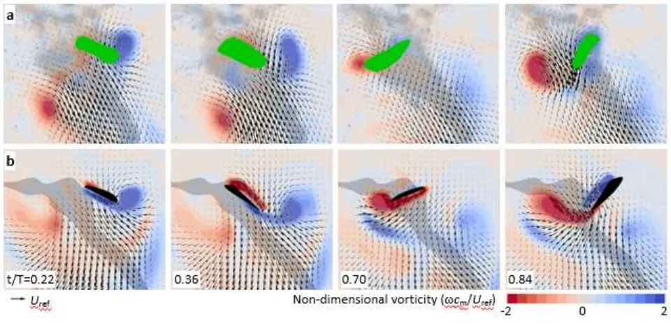
Figure 2. Validation of CFD (a) with PIV (b) quantitative flow fields. Left-to-right: End of
385
pronation (t/T = 0.22), late downstroke (t/T = 0.36), end of supination (t/T = 0.70) and late
386
upstroke (t/T = 0.84); green shading shows areas of no data. Red and blue patches show
387
clockwise and anticlockwise vorticity. Flow velocity field planes are shown at R = 0.5 wing
388
length for both CFD and PIV.
389
Figure 3. Aerodynamic forces generated by the wings and the mechanisms that produce them:
391
trailing-edge vortices, leading-edge vortices and rotational drag. a, single-wing total
392
aerodynamic force (red), lift (black), drag (blue) and side-force (green). b, lift from CFD (black)
393
compared against a simple steady model (grey). Orange shading shows where the
quasi-394
steady model over-predicts the force estimate from the CFD simulation, whereas green shows
395
under-prediction. c, partitioning of the lift force (black) into the portion derived from the
396
integrated pressure on the anterior half of the wing (purple), the posterior half (cyan), and the
397
viscous contribution (dashed). Note the fluctuating contributions during the downstroke (t/T =
0-398
0.5). d, aerodynamic power. e, the effect of increasing wing stroke amplitude (see insert for
399
range) while maintaining mean wing tip velocity is to reduce the relative contribution to lift
400
attributable to unsteady effects. f-j, surface pressure at t1-t5 on the wing (blue to red shading).
401
Overlain are instantaneous streamlines (grey) and flow velocity vectors (black arrows) for
402
selected vertical slices through the three-dimensional flow field at planes 0.6R or 0.75R from
wing base. Body (dashed line) and wing outlines (solid line, leading edge in bold) are shown for
404
orientation.
405
406
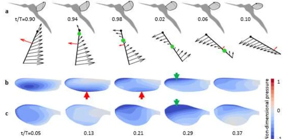
Figure 4. Wing pronation. a, the end of each half stroke in mosquitoes is characterized by a shift
408
in the rotational axis (green dot) from leading to trailing edge. Black arrows indicate local
409
motion of the wing during pronation (at 0.75R, indicated in top row); red arrows indicate the
410
resultant aerodynamic force vector (depicted at the chord-wise centre of pressure). Despite rapid
411
pitching down at t/T=0.10 and faster motion of the leading edge, the trailing edge remains almost
412
stationary yet generates the majority of the lift at this instant due to the formation of a trailing
413
edge vortex caused by the induced flow from the preceding upstroke. Pressure distributions
414
(shaded blue to red) on the upper surface of the mosquito (b) and fruit fly (c) at five moments
415
through the downstroke. Red arrows in (b) show the signature of the trailing-edge vortex,
416
visualised by a region of intense low pressure along the trailing portion of the wing, which is not
417
present on the fruit fly wing (c). Later in the downstroke, a low pressure region from the
leading-418
edge vortex starts outboard and grows towards the wing root, as described elsewhere29 for both
419
species (green arrow).
420
421
Extended Data Figures
423
Extended Data Figure 1. Mosquito kinematics acquisition rig, wing lengths and mean
424
kinematic patterns. a, CAD representation and b, photograph of the apparatus used to record the
425
body motion and wing kinematics of mosquitoes. The recording volume lies at the intersection of
426
the fields of view of eight high-speed cameras, each creating a silhouette image of the mosquito
427
by the shadow from high power IR-LED illumination. c,wing length estimates for mosquitoes
428
captured in each of 15 sequences (M01-M15). Each estimate shows the median as a black line
429
with shading representing the 95% confidence interval based upon all wing beats from each
430
sequence. Green and purple boxes group sequences that could not be reliably separated using
431
Tukey’s Honestly Significant Difference criterion, although they may come from different
432
individuals of very similar size. As such, our fully-processed dataset of 15 sequences comprises
433
between 12 and 15 individual mosquitoes. d, mean wing beat kinematics for all wingbeats in
434
each of 15 recorded sequences. With reference to c, M01, M06 and M09, coloured green, may be
435
from the same individual. Similarly, M05 and M11 may also be from a single individual.
436
Extended Data Figure 2. Wing surface pressure distribution and fluid flow visualised by
439
streamlines showing consistency across each of the 15 mosquito sequences. Each image
440
corresponds to key instant t1. Formation of the trailing-edge vortex due to capture of the induced
441
flow from the preceding upstroke causes a distinct region of low pressure on the posterior
442
portion of the wing.
443
444
Extended Data Figure 3. Wing surface pressure distribution and fluid flow visualised by
446
streamlines showing consistency across each of the 15 mosquito sequences. Each image
447
corresponds to key instant t2. The downstroke force peak is dominated by a leading-edge vortex
448
and corresponding low pressure on the anterior portion of the wing. The trailing-edge vortex has
449
usually shed by this point in the stroke cycle.
450
451
Extended Data Figure 4. Wing surface pressure distribution and fluid flow visualised by
453
streamlines showing consistency across each of the 15 mosquito sequences. Each image
454
corresponds to key instant t3. A low pressure region is evident on the posterior portion of the
455
wing due to lift from rotational drag as the wing rotates around an axis close to the leading edge.
456
457
Extended Data Figure 5. Wing surface pressure distribution and fluid flow visualised by
459
streamlines showing consistency across each of the 15 mosquito sequences. Each image
460
corresponds to key instant t4. Formation of a trailing-edge vortex on the aerodynamic upper,
461
(anatomical ventral) surface of the wing during the upstroke due to capture of the induced flow
462
from the preceding downstroke causes a distinct region of low pressure on the posterior portion
463
of the wing.
464
465
Extended Data Figure 6. Wing surface pressure distribution and fluid flow visualised by
467
streamlines showing consistency across each of the 15 mosquito sequences. Each image
468
corresponds to key instant t5. A low pressure region exists over much of the aerodynamic upper,
469
(anatomical ventral) surface of the wing as the result of a combination of rotational drag (caused
470
by wing rotation around an axis close to the leading edge) and the remnants of the upstroke’s
471
leading-edge vortex (which is no longer coherent in most examples but is retained in M03, M04,
472
M06, M08, M11).
473
474
Extended Data Figure 7. Comparison of the local flow conditions at the trailing edge of the
476
wings of mosquitoes and fruit flies during pronation (t/T=0.09). The comparatively higher local
477
angle of attack at the mosquito is caused by the induced flow from the preceding upstroke. This
478
is a product of kinematic tuning and a form of wake capture that leads to roll up of a transient,
479
coherent, trailing-edge vortex. The vortex contributes to weight support along much of the length
480
of the slender mosquito wing, despite it having little ground velocity during the rotational phase
481
of the stroke cycle.
483
Extended Data Figure 8. Comparison of computed CFD lift force (black) compared against a
485
simple quasi-steady model (grey) for each of 15 mosquito flight sequences. Orange shading
486
shows where the quasi-steady model over-predicts the force estimate from the CFD simulation,
487
whereas green shows under-prediction. (See also Fig. 3)
488
489
Extended Data Figure 9. Lift and drag polars from high-fidelity CFD simulations of the
491
mosquito wing model in continuous rotational sweep at four Reynolds numbers. These were used
492
to create dynamic lift coefficients for the blade element modelling with quasi-steady assumption.
493
Coefficients are calculated for the third rotation, to account for the reduction in effective angle of
494
attack when wings operate in the induced downwash from the preceding wing stroke.
495
496
Extended Data Figure 10. Morphology extraction (a, c) and the CFD grid used for simulations
498
(b, d-f). We used the mean wing planform of three mosquitoes, extracted from microscope
499
images of recently excised wings, to generate the wing grids used in our CFD simulations. The
500
body shape was approximated from the silhouettes in the raw video data by fitting ellipses
501
normal to the central axis of the body taken from each of the eight camera views. g, CFD grid
502
and time-step independence was verified after performing simulations with variable cell density
503
and time-step intervals.
505
Supplementary Video. Video showing: i) the experimental apparatus, ii) raw data, iii) wing
507
geometry routine, iv) kinematics, v) vortex wake (using isosurfaces of the Q-criterion), and vi)
508
pressure distribution and instantaneous flow fields at key instants (t1-t5) throughout the wing
509
stroke cycle.
510
Available via Nature online:
511
https://www.nature.com/nature/journal/v544/n7648/fig_tab/nature21727_SV1.html
512