Article
Verification Platform for Plant AVC Substations
based on Digital Simulation Technology
Fuxing Li 1, Yang Du 1 , Lei Tang 2, Enqi Liu 3 , Jiapei Zhu 3 and Wenbin Zhao 3*
1 State Grid Shanghai Electric Power Research Institute, Shanghai, 200437, China; [email protected] 2 Beijing KingStar High-tech System Control Co. Ltd, Haidian District, Beijing 100083, China;
3 Shanghai University of Electric Power, Shanghai 200090, China; [email protected]
* Correspondence: [email protected]; Tel.: +86-138-1869-5350
Abstract: Generator automatic voltage control device (AVC) is an automatic voltage and reactive power optimization control terminal on the power plant side. Aiming at improving the performance of generator automatic voltage control device, this paper introduces a detection method of AVC substation performance based on virtual dispatching terminal environment. During the testing, the upper computer of redundant power plant is connected to the virtual dispatching terminal environment to simulate the sending instructions of AVC master station, the behavior of AVC sub stations and the excitation system of generators. The performance of AVC substation is evaluated according to the feedback adjustment results, which can effectively detect the abnormal behavior of AVC substation in power plant.
Keywords: automatic voltage control (AVC); virtual dispatching master station; simulated power system; digital simulation
1. Introduction
Automatic voltage control (AVC) system plays an important role to realize safe and economical operation of transmission power grid, which can reduce network loss and improve voltage stability margin and quality rate [1]. AVC system is superior to power grid Energy Management System (EMS) in frame. It takes advantage of the real-time running data in transmission power grid to optimize reactive power and voltage considering global optimization [2-3], and then command the power plant, substation and other power dispatching organization to carry out the scheme. Generally, AVC system consists of AVC master station running in dispatching center and AVC sub-stations deployed in power plants [4-7]. AVC master station can calculate the voltage control target value of high-voltage bus [8] and send it to AVC sub-stations. According to the target value, AVC sub-stations can regulate reactive power output of generator to meet voltage requirement [9-12].
With the development of power grid, the scale of external ultra-high voltage (UHV) direct current (DC) transmission in East China is increasing rapidly. Thus, the internal power startup and reactive power backup is inadequate and the voltage regulation is more difficult [13-17]. Therefore, the demand of reactive power, regulation ability of voltage and response speed of plant are increasing gradually [18]. At present, the dispatching center of East China power grid and Shanghai power grid connect 500kV and 200kV power plants to AVC control, and build AVC sub-stations to implement reactive power automatic control for generator units. The performance of AVC sub-stations is one of the main factors that influence East China power grid reactive power regulation. In this paper, a detection platform of power plant AVC sub-stations’ performance is proposed based on the integrated power grid control digital simulation technology, which can improve the regulation ability of reactive power and ensure East China power grid operate safely
and stably. The detection platform can evaluate the voltage control algorithms and software functions beforehand so that shortcoming of AVC sub-stations can be detected and overcame before the closed-loop control.
2. Virtual environment for AVC system
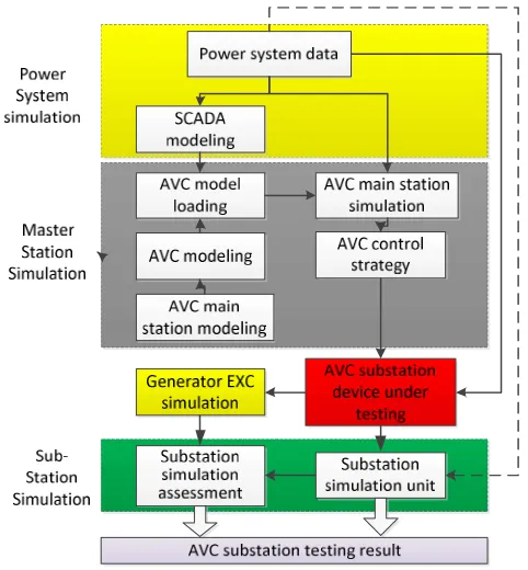
The detection platform constructs the global power grid models that can be observed by each control center. Then it uses continuous power flow calculations to simulate continuous changes in power grids. Finally, the system realizes the closed-loop control by simulating AVC sub-stations technology[8]. The structure of the virtual dispatch environment for detecting AVC substations’ performance is shown in the Figure 1.
As is shown in Figure 1, the virtual dispatch environment of AVC substation consists of four parts, i.e., power system simulation, master station simulation, substation simulation and AVC testing unit.
Figure 1 shows the composition of the virtual dispatch environment, of which the red part is the device to be detected. The simulated power system is composed of various regional power grid models. The main idea is to comply with the real power grid data and realize the power grid environment. The simulation system can imitate the power flow after obtaining part of the real section data from the power grid and generate the continuous power flow simulation data.
At the same time, the AVC master station model and the power plant model can be obtained after splitting the simulated power system. AVC master station unit is a control model corresponding to the power grid, simulating the on-site AVC master station to perform the control strategy and send instructions. The AVC substation simulation unit is a substation model corresponding to the power plant. It can receive the instructions of master station and simulate the functions of the plant for generator excitation regulation. The AVC substation unit evaluates the result of reactive power adjustment of the power plant and verify the performance of the substation.
Figure 1. The composition of the virtual dispatch environment
models. The main idea is to comply with the real power grid data and realize the power grid environment. The simulation system can imitate the power flow after obtaining part of the real section data from the power grid and generate the continuous power flow simulation data.
At the same time, the AVC master station model and the power plant model can be obtained after splitting the simulated power system. AVC master station unit is a control model corresponding to the power grid, simulating the on-site AVC master station to perform the control strategy and send instructions. The AVC substation simulation unit is a substation model corresponding to the power plant. It can receive the instructions of master station and simulate the functions of the plant for generator excitation regulation. The AVC substation unit evaluates the result of reactive power adjustment of the power plant and verify the performance of the substation.
The simulated power system is the core of the whole detection platform. For practical application, it can simulate the actual operating data of the power grid to test the response characteristics of the AVC substation. The virtual dispatching terminal conforms to the requirements of D5000 system, and can provide the basic power grid data for AVC master station module and AVC substation module.
The AVC master station receives the simulated power grid data and generates the control strategy, and the control strategy is sent to the simulated power system.
After the AVC master station sends control instructions to the detected substation device, the AVC substation can obtain the power plant model from the simulated power system and collect the current grid data for calculation. The control data can be calculated and be sent to the detected substation. After receiving the instructions, the AVC substation can interact with the generator excitation device to simulate the plant adjustment interaction. After the adjustment is completed, the feedback data is transferred to the power system. Then the substation mode is controlled. Based on the data analysis of the substation's control behavior, the evaluation unit gives the test report of the AVC substation.
3. Digital Simulation Technology
3.1. Simulation model preparation
1. Based on the IEC61970 standard, an integrated global digital simulation model (IGDSM) is established by combination. The model contains 220kV and above power gird. In the model, the grid parameters of 500kV and above come from East China power grid dispatching center, and 220kV and below come from province-level power grid dispatching center.
2. Based on the IGDSM, the digital simulation environment in power grid steady state closed-loop control is built by the method of load flow calculation.
3. The AVC master station simulation module obtains the region-level or province-level power grid model from IGDSM, and builds AVC control model according to actual demand.
4. The AVC sub-stations to be tested obtain the equipment model inside the power plant from the IGDSM, and build power plant AVC sub-stations control model according to actual demand.
3.2. Power grid operation simulation
the AVC control, the time span of the section should not be longer than the control cycle of AVC (generally 5 min). 2 types of generating grids section data are given as follows.
1. Single section expansion
An actual section at a certain time from power system is set as the initial state. According to the total load variation curve after the initial state, the generation and load data of each section in a given period time could be obtained based on the same proportion of growth. In the process of fitting, deviation of the whole network loss will be accumulated on the balance machine. Therefore, it is necessary to regulate the active output of the generator to avoid the abnormal output of the balance machine according to the deviation.
2. Multi-section fitting
Some actual sections at a certain period of time from power system might not meet the simulation requirement because of long time span (15~60 min) between the sections. These data sections can be used as the basis for fitting the continuous change state of the grid during that period. In the process of fitting, it is necessary to revise the output of the whole network according to the change of balance machine, so as to avoid the divergence of the load flow calculation.
3.3. Close-loop control simulation
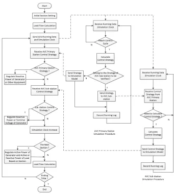
Based on the continuous load flow calculation, the process of simulating the closed-loop control is shown as follows
1. Firstly, we should set start time and select multiple sections. A load flow calculation is carried out with the first section as the simulation start time.
2. The results of load flow calculation, together with the simulation clock time, are sent to the AVC main station simulation module.
3. The results of load flow calculation, together with the simulation clock time, are sent to the AVC sub-stations to be detected.
4. The AVC master station calculates and simulates the control strategy according to the grid operation state, the current simulation clock time and cycle.
5. The AVC sub-stations to be verified calculate reactive power or voltage regulation strategy of generator units according to the control strategy from AVC master station. And then send the regulation strategy to IGDSM.
6. In the IGDSM, load flow calculation should be carried out after the reactive power output of generators and other reactive power equipment are regulated.
7. According to the simulation process, the increasing simulation clock step size of the parameters is generally set as 10~15s.
8. If the current state has reached the next section, active power output of generator and active power and reactive power of load can be regulated based on the section data. (reactive power of generator controlled by AVC is not considered in this step). Then, load flow calculation can be carried out based on the regulation.
9. Return to step 2 for the next round of closed-loop control simulation.
Figure 2. Flow chart of the AVC closed-loop simulation
4. Simulation of Plant AVC Substation Control
From the overall scheme, the detection system can make the complete simulation of AVC closed-loop automatic control. In the simulation, AVC sub-station is controlled in the following methods.
1. For the AVC sub-station to be verified, a set of AVC sub-station consistent with the power plant scene is linked to the detection platform. In the simulation, AVC sub-station receive instructions about voltage on high-voltage side from the AVC master station, and adopt algorithm consistent with the scene to calculate the generator reactive power control strategy. Then, the load flow calculation is carried out by the grid simulation model.
2. For other AVC sub-stations, AVC master station make the high voltage regulation and send it to AVC sub-stations.
4.1. For AVC sub-station to be verified
slave computer is the actuator of the generator's reactive voltage regulation. Typical structure and simulation work flow of AVC sub-station system are shown in Figure 3 and Figure 4, respectively.
For the AVC sub-station involved in the verification, the redundant configuration of the host computer is connected to the verification platform. The host computer uses the current power plant operation state from the platform to calculate the reactive power or voltage regulation strategies, and then sends them back to platform. Generally, the data interaction cycle is 10~20 s.
Figure 3.Structure of power plant AVC substation system
According to the on-site implementation of power plant, AVC sub-station can send the regulation instructions of reactive power or the terminal voltage to the verification platform. For the reactive power regulation, the generator is set as a PQ node, and the reactive power of generator is regulated to carry out load flow calculation. For the terminal voltage regulation of generator, the generator is set as a PV node, and the terminal voltage of generator is regulated for load flow calculation.
4.2. Simulation of AVC sub-station close-loop control
The AVC main station system sends the target value of voltage control or total plant reactive power command of the high voltage side busbar of power plant transformer to the plant side AVC substation system in real time.
According to the control target value and a certain control strategy, the reactive power output target value of each unit is calculated. Then the AVC mater station directly delivers the reactive power output target value of each unit to the AVC substation system on the power plant side in real time. The AVC substation system sends the demagnetization signal to the excitation system of the generator to adjust the reactive power output of the generator directly or through the distributed control system (DCS) system, so that the voltage of the high voltage side bus of the power plant or the reactive power output of each unit is forced to the target value, and the closed-loop control of the AVC substation system and AVC master station system on the power plant side is formed.
4.3. Simulation of AVC sub-station open-loop control
The AVC mater station sends the voltage planning curve of the plant-side bus to the AVC substation system, or record the voltage planning curve periodically or manually. When the communication with the AVC master station is interrupted, the plant-side AVC substation system is interrupted. When exiting closed-loop operation, the voltage curve will be automatically tracked for adjustment.
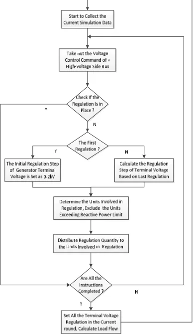
4.4. Control of Reactive Output of Generator in AVC Substation of Power Plant
After the power plant AVC substation system receives the control instructions, the voltage of the high voltage bus is adjusted. The substation system calculates the total reactive power target value that the plant should deliver to the system. According to the deviation between the target value and the measured value, reactive power is distributed among the generators as the predetermined scheme. With various constraints satisfied, the principle computer sends a reactive power adjustment command to the slave machine of each unit, and the slave machine adjusts the reactive power output of the generator by changing a given value of the generator AVR. The plant always maintains the high voltage bus voltage at the target value when the high voltage bus voltage target value command is not changed.
The method for calculating voltage and reactive power is as follows. 1. The target value of reactive power on high-voltage side bus
the total reactive power sent to the system is Q j. The system reactance is denoted by X, so the target value of total reactive power sent to the system by the generators is calculated in equation (1):
(
)
j i i j j
i
U
U
Q
Q
U
X
U
(1)
Therefore, based on U i, Q i, U j and X, the target value Q i of total reactive power sent to the system can be determined. System reactance X is undetermined in the above equation.
2. System Reactance X
The system reactance can be determined according to the equation (2).
Q
k/
U
k
Q
k/
U
k
X U
k
U
k(2)
Where, Qk+, Qk-, Uk+, Uk- are the total reactive power and high-voltage side bus voltages of the input system before and after the kth reactive power adjustment for all generators, respectively.
3. Reactive power distribution among generators
According to the upper and lower limits of the reactive power of each generator at the current operating point, the ideal reactive power output of each unit is taken as the target value, and the deviation of the total target value from the total ideal reactive power is taken for the adjustable reactive power of each unit. Coefficients are assigned to obtain the target output reactive power of each generator.
4. Calculation of the reactive power consumed by the transformer and the generator
According to the terminal current, the main transformer impedance, the equation (3) is adopted to calculate the reactive power consumed by the transformer.
2
3
T T
Q
I X
(3)
The reactive power consumed by the generator can be set to a fixed value according to the reactive power of the generator during normal operation.
4.5. Assessment unit of AVC substations’ performance
Assessment unit of AVC substations’ performance evaluates the voltage regulation results. Compared with reference [1], this paper adds the following two performance assessments based on the performance evaluation of AVC substations.
1. Case record
AVC system should have the function of event recording function.
AVC System Monitoring Center is required to have the function of time synchronization with GPS in order to ensure that the time of event recording is accurate. The monitoring center communicates with the GPS via the serial port in the form of messages.
2. Start and exit methods
Local control: The voltage and reactive power automatic control system monitoring center shall be able to start or exit the terminal of the system.
5. Assessment of Power Plant AVC Sub-stations’ Performance
The verification platform can simulate the performance of AVC sub-station in real power grid and assess the performance. Meanwhile, the platform can verify security monitoring and locking of AVC sub-stations of under various abnormal conditions.
5.1 Verification for control strategy of AVC sub-station of power plant
1. The reactive power of the units can be optimized according to different distribution principles such as equal power factor, equal reactive margin, and equal apparent power.
2. The AVC sub-station in local control mode can control the power plant voltage in accordance with the preset voltage curve.
3. Multiple parallel running buses are monitored at the same time. When any bus is checked or out of order, it can automatically switch to another bus and send the current bus information to the AVC master station.
5.2 Verification for security monitoring function of AVC sub-station of power plant
When the communication between AVC sub-station and remote control system fails, if the bus data collection fails, all the units regulation under the section bus will be locked. If the unit data collection fails, all units regulation will be locked.
1. In remote control mode, when the communication with AVC master station fails, it can automatically switch to local control mode, and lock all the units regulation under the bus. 2. When the measurement data of bus voltage exceeds the valid range, the bus is changed to
monitor another bus. If the measured data is still out of the valid range, all units regulation under the bus will be locked. If the measurement data of the unit's active power, the unit’s reactive power, the unit’s stator voltage, the unit’s stator current exceeds the valid range, all units regulation will be locked.
3. If the AVC master station command exceeds the setting limit, the instruction is automatically corrected to the limit to keep the bus voltage is limited properly.
5.3 Verification for security monitoring function of AVC sub-station of power plant
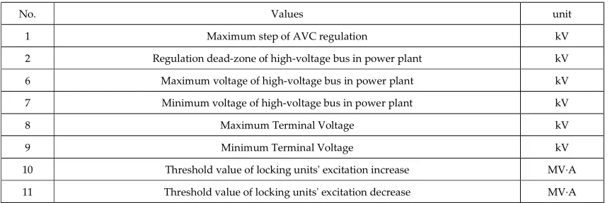
In the platform, the setting value of AVC sub-station can be checked to find whether it meets the requirements of the Power Grid Corporation. The setting value is shown in Table 1.
Table 1. Detectable setting values of AVC substations
No. Values unit
1 Maximum step of AVC regulation kV
2 Regulation dead-zone of high-voltage bus in power plant kV
6 Maximum voltage of high-voltage bus in power plant kV
7 Minimum voltage of high-voltage bus in power plant kV
8 Maximum Terminal Voltage kV
9 Minimum Terminal Voltage kV
5.4 Verification Platform for AVC sub-station of power plant
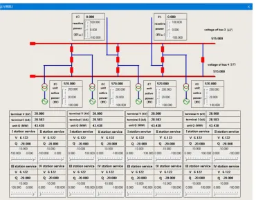
After the AVC master station issues the power plant high-voltage voltage control command, the power plant-side AVC substation shall calculate the control strategy according to the actual output of each unit in the plant. The interface shown in Figure 5 shows the real running status of each unit in the power plant, which can read out the power plant real-time operation information such as reactive power output of each bus and unit, terminal voltage and terminal current of each unit.
Figure 5.Interface of generator operation information
After the power station side substation calculates the control strategy, the excitation of each unit will be adjusted according to the control strategy.
6. Conclusions
To improve the reactive power automatic control of East China power grid, a verification platform of power plant AVC sub-stations is proposed based on the power grid digital simulation technology. The core of the platform is the IGDSM, which can be used for continuous digital simulation of the power grid operation, AVC master station and sub-station. The detection platform can detect the abnormal behavior of AVC sub-stations so as to improve the performance of automatic voltage control in the power grid.
References
2. Tibor, H; Tarek, A; Kevin, S. Xue L. “Dynamic Voltage Scalin in Multitier Web Servers with End-to-End Delay Control.”, IEEE Transactions on Computers ,2007, 4(56), pp.444-458. DOI. Available online: 10.1109/TC.2007.1003 (accessed on 12 June 2017).
3. Wang, F. H; Li ,H.; Chen, H. “Coordinated secondary voltage control to eliminate voltage violations in power system contingencies”. IEEE Transactions on Power Systems, 2003, 2(18), pp. 588-595. DOI. Available online: 10.1109/TPWRS.2003.810896 (accessed on 22 June 2017).
4. Anna, K. S.; Repo, P. J. “Coordinated voltage Control in Distribution Networks Including Several Distributed Energy Resources ” IEEE Transactions on Smart Grid, 2014, 4(5), pp. 2010-2020. DOI. Available online: 10.1109/TSG.2014.2297971 (accessed on 21 July 2017).
5. Wildberger, A. M. “Complex adaptive systems: concept and power industry applications.” IEEE Control Systems, 1997, 6(17), pp. 77-88. DOI. Available online: 10.1109/37.642976 (accessed on 29 July 2017). 6. Michel, L. “Review of New Developments in the Modeling of Lighting Electrmagnetic Effects on
Overhead Lines and Buried Cables.” IEEE Transactions on Electromagnetic Compatibility, 2007, 2(49), pp.224-236. DOI. Available online: 10.1109/TEMC.2007.897149 (accessed on 30 July 2017).
7. Nitaigour, P. M.; Kiseon K. “A Prototype for Hardware-in-the-Loop Simulation of a Distribution Control Architecture.” IEEE Transactions on Systems, Man and Cybernetics, Part C (Applications and Reviews), 2008, 2(38), pp.189-200. DOI. Available online: 10.1109/TSMCC.2007.913891 (accessed on 30 July 2017).
8. Keerthi, S.S.; Shevade, S. K.; Bhattacharyya, C.; Murthy, K. RK. “Improvements to platt’s SMO Algorithm for SVM Classifier Design.” Neural Computation, 2001, 3(13), pp. 637-649. DOI. Available online: 10.1162/089976601300014493 (accessed on 30 August 2017).
9. Fardanesh, B. “Future trends in power system control ” IEEE Computer Applications in Power, 2002, 3(15), pp. 24-31. DOI. Available online: 10.1109/MCAP.2002.1018819 (accessed on 05 September 2017).
10. Yoshida, H.; Kawata, K.; Fukuyama, Y.; Takayama, S.; Nakanishi, Y. "A particle swarm optimization for reactive power and voltage control considering voltage security assessment," IEEE Transactions on Power Systems, 2000, 4(15), pp. 1232-1239. DOI. Available online: 10.1109/59.898095 (accessed on 30 September 2017).
11. El-Khattam, W.; Hegazy, Y. G.; Salama, M. M. A. "An integrated distributed generation optimization model for distribution system planning," IEEE Transactions on Power Systems, 2005, 2(20), pp. 1158-1165. DOI. Available online: 10.1109/TPWRS.2005.846114 (accessed on 30 September 2017).
12. Prasad, G.; Swidenbank, E.; Hogg, B. W. "A novel performance monitoring strategy for economical thermal power plant operation," IEEE Transactions on Energy Conversion, 1999. 3(14), pp. 802-809. DOI. Available online: 10.1109/60.790955 (accessed on 30 September 2017).
13. Chowdhury, A. A.; Agarwal, S. K.; Koval, D. O.; "Reliability modeling of distributed generation in conventional distribution systems planning and analysis," Conference Record of the 2002 IEEE Industry Applications Conference. 37th IAS Annual Meeting (Cat. No.02CH37344), Pittsburgh, PA, USA, 2002, pp. 1089-1094, vol.2.
14. Martins, N.; Lima, L. T. G.; "Determination of suitable locations for power system stabilizers and static VAR compensators for damping electromechanical oscillations in large scale power systems," IEEE Transactions on Power Systems, 1990, 4(5), pp. 1455-1469. DOI. Available online: 10.1109/59.99400 (accessed on 30 September 2017).
15. Zimmerman, R. D.; Murillo-Sanchez, C. E.; Thomas. R. J. "MATPOWER: Steady-State Operations, Planning, and Analysis Tools for Power Systems Research and Education," IEEE Transactions on Power Systems, 2011 1(26), pp. 12-19. DOI. Available online: 10.1109/TPWRS.2010.2051168 (accessed on 30 September 2017).
16. Sun, H., Guo, Q.; Zhang, B.; Wu, W.; Tong, J. "Development and applications of system-wide automatic voltage control system in China," 2009 IEEE Power & Energy Society General Meeting, Calgary, AB, 2009, pp. 1-5.
17. Sun, H.; Guo, Q.; Zhang, B.; Wu, W.; Wang, B. "An Adaptive Zone-Division-Based Automatic Voltage Control System With Applications in China," IEEE Transactions on Power Systems, 2013, 2(18), pp. 1816-1828 . DOI. Available online: 10.1109/TPWRS.2012.2228013 (accessed on 30 September 2017). 18. Bloemink, J. M.; Green, T. C. "Benefits of Distribution-Level Power Electronics for Supporting Distributed