http://www.sciencepublishinggroup.com/j/com doi: 10.11648/j.XXXX.2018XXXX.XX
ISSN: 2328-5966 (Print); ISSN: 2328-5923 (Online)
Communication
RNS Based on Shannon Fano Coding for Data Encoding
and Decoding Using {2
n
-1, 2
n
, 2
n
+1} Moduli Sets
Idris Abiodun Aremu
1, Kazeem Alagbe Gbolagade
21
Computer Science Department, Lagos State Polytechnics, Lagos, Nigeria
2
Department of Computer Science, Kwara State University, Kwara, Nigeria
Email address:
To cite this article:
Idris Abiodun Aremu, Kazeem Alagbe Gbolagade. RNS Based on Shannon Fano Coding for Data Encoding and Decoding Using {2n-1, 2n, 2n+1} Moduli Sets. Communications. Vol. 6, No. 1, 2018, pp. 25-29. doi: 10.11648/j.com.20180601.15
Received: January23, 2018; Accepted: February 1, 2018; Published: March 16, 2018
Abstract:
The main objective of any communication system is to transmit data with minimum error rate in data communication. This paper presents information encryption and decryption in data communication with Shannon fano compression techniques using Residue Number System (RNS). The current network communication system involves exchange of information with highly secured data and reduction in both the space requirement and speed for data storage and transmission. For this purpose error detection and correction techniques are used, Our proposed scheme uses the Chinese Remainder Theorem (CRT) which are smaller and needs to be performed in parallel, therefore from the first decoding we can easily identify if error is in a channel. The algorithm applies CRT to detect, locate and correct error by eliminating look up table, therefore the scheme provides a memory less based scheme. It uses a pipelining approach to breakdown the problem with a level of complexity O(n) after decoding and performing consistent checks on all the residue, therefore the overall delay will be lesser and efficient.Keywords:
Shannon Fano, Residue Number System, Forward Conversion, Information Encryption and Decryption, Mixed Radix Conversion1. Introduction
Cryptography is the art and science of using cryptographic techniques, performing the cryptographic techniques in designing a secure cryptosystem [1], [2], [3]. The current network communication system involves exchange of information with highly secured data and reduction in both the space requirement and speed for data storage and transmission [2], [4]. In order to reduce the cost of both data storage and communication, there is a need to reduce the redundancy in the data representation, which is, compressing the data [5], [6]. Compression is a technology for minimizing the amount of data used to represent any content without excessively reducing the quality of the data [6]. The Residue Number System (RNS) that supports carry free, low power, parallel, high speed, and is applied to secure computing to enhance the Shannon fano coding algorithm using length three traditional moduli set. RNS are alternative representations to positional number systems [7]. The primary benefit of
RNS is that their carry-free arithmetic can be computed both independently and in parallel in which each of the channels canperform integer addition, subtraction and multiplication [ 7 ] . RNS is defined in terms of a relatively prime moduli set , , , … , such that
gcd , 1 for , where gcd means the greatest common divisor f and while ∏ , is the dynamic range (Gbolagade, 2010). The residues of a conventional number can be obtained as | | . Thus can be represented in RNS as , , , … , , 0 "
# . This representation is unique for any integer ∈
%0, & 1'. For a signed number system, any integer
& |2, |2 has a RNS representation where,
'M’ (Dynamic Range), we say that an overflow has occurred which makes RNS representations to repeat itself. Also, representations in a system in which moduli sets are not pairwise relatively prime will not be unique as 2 or more numbers that are nominally different will have the same representation in the RNS representations.
Example 1
Given the moduli set 7, 8, 9 , the number 120 can be represented in RNS as;
| | 1 |120|2 1; | | 4 |120|5 0;
| | 6 |120|7 3
Thus, the RNS representation of 120 is 1, 0, 3 9:; 2,5,7 . Several recent contributions exist in data compression and encryption, which tend to view the subject from the outlook of data transmission only and overlooked the core value of compression in data storage. In this paper, the discussion will be centred on encoding and decoding of data for storage known as cryptograph and transmission through network communication channels. Thus, the study is focus on an
algorithm for data compression by adopting both the traditional Shannon Fano method and RNS for data encoding but deal not with hardware component of the compression.
The idea of data encryption was originated from [10], such that, the source message and their corresponding probabilities are arranged in order of increasing probabilities and then divided into two groups of nearly equal total possible probabilities. Each of the source messages in the first group is then assigned with „0‟ as the first codeword and those in the second group are assigned with „1‟ as their first codeword. The process is repeated until smallest possible groups are reached. The scheme in [11] proposed a design of Encoding Calculator Software for Huffman and Shannon-Fano Algorithms, design helps to easily realize the algorithms without going into a cumbersome, tedious and prone to error manual mechanism of encoding the signals during the transmission. In this research, we proposed an RNS coding based on Shannon fano coding to have better result compared with the state of the art in term of both security and time/space.
2. Proposed Scheme
Figure 1. Framework for the Proposed Scheme.
At the sender site, message to be sent is compressed by Shannon Fano transformation and then encoding using RNS forward conversion, and send via the internet. At the receiver site, the encrypted message received is decrypted using RNS reverse conversion.
2.1. Shannon Fano Encoding
A Shannon-Fano tree is built according to a specification designed to define an effective code table. The actual algorithm is simple:
1.For a given list of symbols, develop a corresponding list of probabilities or frequency counts so that each symbol’s relative frequency of occurrence is known. 2.Sort the lists of symbols according to frequency, with the
most frequently occurring symbols at the left and the least common at the right.
3.Divide the list into two parts, with the total frequency counts of the left half being as close to the total of the right as possible.
4.The left half of the list is assigned the binary digit 0, and
the right half is assigned the digit 1. This means that the codes for the symbols in the first half will all start with 0, and the codes in the second half will all start with 1. 5.Recursively apply the steps 3 and 4 to each of the two
halves, subdividing groups and adding bits to the codes until each symbol has become a corresponding code leaf on the tree.
2.2. Shannon Fano Algorithm Application
A simple example will be used to illustrate the algorithm:
Table 1. Frequency table of information to be encode using Shannon Fano.
SYMBOLS FREQUENCY
A 15
B 7
C 6
D 6
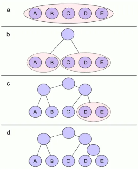
Figure 2. Binary tree of the Shannon Fano.
All symbols are sorted by frequency, from left to right (shown in Figure2). Putting the dividing line between symbols B and C results in a total of 22 in the left group and a total of 17 in the right group. This minimizes the difference in totals between the two groups.
With this division, A and B will each have a code that starts with a 0 bit, and the C, D, and E codes will all start with a 1, as shown in Figure b. Subsequently, the left half of the tree gets a new division between A and B, which puts A on a leaf with
code 00 and B on a leaf with code 01.
After four division procedures, a tree of codes results. In the final tree, the three symbols with the highest frequencies have all been assigned 2-bit codes, and two symbols with lower counts have 3-bit codes as shown table 2 below:
Results in 2 bits for A, B and C and per 3 bit for D and E an average bit number of 2.28 Bits per Symbol.
Table 2. Binary table for the transformed message.
Symbols Binary Code
A 00
B 01
C 10
D 110
E 111
2.3. Rns Forward Conversion
The forward conversion is performed by a forward converter which decomposes a weighted binary number into a residue represented number with regards to a moduli set, that is, it is the conversion from a conventional representation to a residue one by dividing the number X by each of the given moduli and then collect their remainder [12].
Example 2. Given moduli set {3, 4, 5}; the number 4 can be represented in RNS as below:
| | … …. (1)
| | 1 |3|= 3; | | 4 |4|= 0; | | 6
|5|= 1
Thus, the RNS representation of 4 is 3, 0, 1 9:; ,=,@ . APPLICATION OF FORWARD CONVERSION TO THE SHANNON FANO TRANSFORMATION
Table 3. Binary table for the transformed message using forward conversion for n=2.
Symbols Binary Code MODULI SET AB& C AB ABD C
A 00 00 00 00
B 01 01 01 01
C 10 10 10 10
D 110 00 10 01
E 111 01 11 10
2.4. Rns Reverse Conversion
The conversion from residue notation to a conventional one (binary or decimal representation) is known as reverse conversion. The two (2) most widely used techniques of reverse conversion are the Chinese Remainder Theorem (CRT) and Mixed Radix Conversion (MRC). Many other methods have been devised but are still based on the CRT and MRC. In this paper we used CRT method for traditional moduli set.
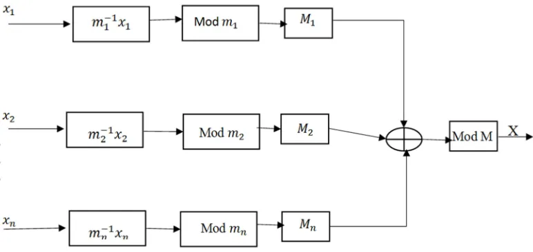
For any RNS representation, decimal equivalent can be obtained with the following equation:
For a moduli set , , … , E with gcd ,
1 F)G and a dynamic range ∏E , the residue
number , , … , E can be converted into the decimal number if the moduli set are coprime with the formula (Omondi and Premkumar, 2007);
H∑E | J | H … …. (2)
Where ∏ and K and J is the
Figure 3. Schematic Diagram of CRT. Source: (Omondi and Premkumar, 2007).
As an example, let us use the CRT to convert our example on forward conversion back to RNS. Computing the value of the integer X which has RNS representation of (1, 0, 4) with respect to moduli set {3, 4, 5}.
Dynamic range (M) = 60, that is 3 L 4 L 5 By the definition of (1) we have
MN | J |
E
M K
Where,
60
3 20; 604 15; 605 12
And also by the definition of multiplicative inverse we have,
J 2; J 3; J 3
Since n = 3 we have
H | J |
1 D | J | 4 D | J | 6 HK
|20 L 2 L 1 D 15 L 3 L 0 D 12 L 3 L 4|PQ
|40 D 0 D 24|PQ
|64|PQ 4
4
3.
Error Detection and Correction
1.Encoding the data information into residue number system representation.
a)Determine the dynamic range of the system
b)Choosing the set of relatively prime integer (moduli sets) for both data and redundant data called information/data moduli sets and redundant moduli set respectively.
c)Perform the forward conversion techniques with
respect to both the information and redundant moduli sets
2. Send the encoded information to the receiver channel. 3. Decode the received information with respect to
information moduli sets
a)Determine the residue representation of the information/data
b)Determine the residue moduli sets
c)Performing reverse conversion techniques on information residue representation with respect with respect to information moduli sets
4. Detection of error in the decoded data / information received
a)Perform forward conversion using MRC technique on the decoded information
b)Performing consistent checking to detect faulty channel
c)If (no error occur) goto STOP Else 5. Error correction
a)Substituting the faulty channel with redundant residue channel
b)Performing base extension techniques with respect to the faulty channel modulo
c)Performing the consistent checking on the result d)If (no error occurred) restore the corrected channel
Else
i) Repeat the step 5 ii) Stop
Example 3
corresponding residue digits, if no errors occurred in the received RNS representation. Let us now attempt to recover the integer represented as {1, 1, 2‟, 0, 10} by considering all possible cases. Once all the possible combinations of four out of six residue digits retained, it results in:
Where, Xijk corresponds to the integer recovered using the
i-th, j-th and k-th moduli and their corresponding residues. From the results we can observe that X134, X135, X234, X235 and
X345 are all in the illegitimate range i.e., their values are out the
range [0, 60). In the remaining cases, 4 out of 5 give the result 21. It can also be observed that all these results were recovered from 3 moduli without including the moduli m3. Thus, we
conclude that 21 is the correct result and that the residue corresponding to m3 i.e., r3 is in error. The correct Value for r3
can be easily computed as rˆ3 = 21(mod 5) =1
4. Performance Evaluation
The proposed scheme was evaluated theoretically in term of complexity, space and security. The scheme provide better security than [12] using Shannon fano coding. The number of iteration is also reduce, to detect and correct single error using 3 moduli set as information data and 2 redundant The amount of memory also needed to design this architecture is expected to reduce Hence, given the same conditions for the error detection and correction at the reverse conversion, the delay in this scheme is expected to be reduced to about 60%.. Table lookup is not required which helps to save memory during implementation.
5. Conclusion
The main objective of any communication system is to transmit data with minimum error rate. For this purpose error detection and correction techniques are used. The numbers of detectable and correctable residue digit errors are governed by the number of redundant moduli. I.e. with r redundant moduli, RRNS is capable of detecting r and correcting |r/2|. Eliminating look-up table by performing more consistent check. Our proposed scheme uses MRC which are smaller and needs to be performed sequentially therefore from the first decoding we can easily identify if error is in a channel. The algorithm applies base extension and MRC to detect, locate and correct error by eliminating table- look up, therefore the scheme provides a memory less based scheme. Locating error is usually time consuming in most algorithm, but in our algorithm, it uses a pipelining approach to breakdown the problem with a level of complexity O(n) after decoding and performing consistent checks on all the residue,
these can be achieved for hardware design we can tell which channel the error has occurred. So therefore the overall delay will be lesser.
References
[1] Diffie, W., & Hellman, M. (1976). New directions in cryptography. IEEE transactions on Information Theory, 22(6), 644-654.
[2] Stallings, W. (2006). Cryptography and network security: principles and practices. Pearson Education India.
[3] Alvarez, G., & Li, S. (2006). Some basic cryptographic requirements for chaos-based cryptosystems. International Journal of Bifurcation and Chaos, 16(08), 2129-215.
[4] Zissis, D., &Lekkas, D. (2012). Addressing cloud computing security issues. Future Generation computer systems, 28(3), 583-592.
[5] Reghbati, H. K. (1981). Special feature an overview of data compression techniques. Computer, 14(4), 71-75.
[6] Lelewer, D. A., & Hirschberg, D. S. (1987). Data compression.
ACM Computing Surveys (CSUR), 19(3), 261-296.
[7] Parhami, B. (1999). Computer arithmetic (Vol. 20, No. 00). Oxford university press.
[8] Gbolagade, K. A., Chaves, R., Sousa, L., & Cotofana, S. D. (2010, May). An improved RNS reverse converter for the {2 2n+1−1, 2n, 2n−1} moduli set. In Circuits and Systems (ISCAS), Proceedings of 2010 IEEE International Symposium on (pp. 2103-2106). IEEE.
[9] Alhassan, A., Saeed, I., & Agbedemnab, P. A. (2015). The Huffman’s Method of Secured Data Encoding and Error Correction using Residue Number System (RNS).
Communication on Applied Electronics (CAE) Journal, Foundation of Computer Science (FCS), New York, USA. [10] Shannon, C. E. (2001). A mathematical theory of
communication. ACM SIGMOBILE Mobile Computing and Communications Review, 5(1), 3-55.8.
[11] Chanhemo, W., Mgombelo, H. R., Hamad, O. F., &Marwala, T. (2011). Design of Encoding Calculator Software for Huffman and Shannon-Fano Algorithms. World Academy of Science, Engineering and Technology, International Journal of Computer, Electrical, Automation, Control and Information Engineering, 5(3), 267-273.