http://www.sciencepublishinggroup.com/j/ajee doi: 10.11648/j.ajee.20190701.11
ISSN: 2329-1648 (Print); ISSN: 2329-163X (Online)
Performance Optimization and Modelization of a
Photovoltaic Pumping System
Mohamed El Mamy Mohamed Mahmoud
1, 2, 4, *, Jeyid Yacoub El Moubarrack
3, Chighali Ehssein
2,
Ahmed Mohamed Yahya
1, Abdel Kader Mahmoud
1, Issakha Youm
41Applied Research Laboratory for Renewable Energies, Mauritania University of Nouakchott, Nouakchott, Mauritania 2
Unit of Electromechanical Research, Institute Superior of Technological Education, Rosso, Mauritania
3
Irrigation Laboratory and Salinity Management, Institute Superior of Technological Education, Rosso, Mauritania
4Laboratory of Semiconductor and Solar Energy, University of Dakar, Dakar, Senegal
Email address:
*
Corresponding author
To cite this article:
Mohamed El Mamy Mohamed Mahmoud, Jeyid Yacoub El Moubarrack, Chighali Ehssein, Ahmed Mohamed Yahya, Abdel Kader Mahmoud, Issakha Youm. Performance Optimization and Modelization of a Photovoltaic Pumping System. American Journal of Energy Engineering. Vol. 7, No. 1, 2019, pp. 1-7. doi: 10.11648/j.ajee.20190701.11
Received: February 16, 2019; Accepted: March 28, 2019; Published: May 23, 2019
Abstract:
The photovoltaic (PV) pumping system is a widely used application in Mauritania to ensure the water supply in rural area for populations needs. The system is composed of a PV generator, a DC/DC converter, a DC/AC inverter, a BLDC motor and a centrifugal pump. Study in this article we study with simulation in Matlab/ Simulink environment the performances of the PV pumping system taking into account the climate parameters (solar irradiance, and ambient temperature), and the effect of the total manometric head (HMT) on the pumped flow rate. In addition it also counted the electrical energy and flow rate of the each climatic parameter. Two mathematical motor –pump models for PV application, were proposed in this article to contribute in the studies of PV pumping sizing. These models link directly the operating current to the voltage and electrical power to the flow rate of the pump versus total head.Keywords:
Generator Photovoltaic, System, Power, Converter, Motor-pump, Flow Rate, Total Manometric Head (HMT)1. Introduction
The water pumping system is one of the applications mostly used in the production of renewable energy. This application is used in the isolated areas (usually isolated mountain areas or rural areas) where we do not have the electricity grid [1].
The populations often use the PV pumping system for the household usage, the water that people need or for irrigation, so this is one of the factors that can play an important role for stability of the rural world life [2].
The dimensioning of PV pumping system studded in [3] and the efficiency of a PV pumping system are mainly based on the effect of solar irradiation. Several research projects have been carried out on the renewable energy conversion systems and their applications which can be summarized in the following two points:
1.The search for precise mathematical models that represent the real photovoltaic cell made it possible to retain the works of [4].
2.The selected models were designed to reflect correctly the influence of different atmospheric conditions on solar cell parameters. In this context, we must not forget to mention other works on optimization methods such as those of [5]. These methods are considered capable of determining the maximum power point of I (V) and P (V) characteristics of the photovoltaic cell.
those of [8].
These different researches have had the objective of proposing a use of PV pumping for any lighting condition and temperature. In this pumping test facility we obtain, for each fixed pumping head, the pumped flow versus input voltage, simultaneously we measure the consumed current and therefore, we get the relation between the curves P-Q and I-V and the pumped flow rate is highly sensitive to the total manometric head (HMT), by comparing with the climatic parameters (solar irradiation and ambient temperature).
2. Description and Modeling of the
Photovoltaic Pumping System
2.1. System Description
The system studied is shown in Figure 1, we have three parts that make up the PV pumping system; A PVG consisting of two PV panels connected in series with a capacity of 190 Wp for each, a DC/DC power converter, and a permanent magnet DC motor coupled directly to a centrifugal pump.
The PV panel parameters are shown in table 1. The Lorentz ps1200 c-sj8-5 used includes a multistage centrifugal pump, sensor less PM BLDC motor and a controller. The controller performances are shown in table 2 [9].
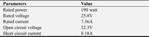
Table 1. Datasheet of the ASTROPOWER MODEL AP 190.
Parameters Value
Rated power 190 watt
Rated voltage 25.8V
Rated current 7.36A
Open circuit voltage 32.3V
Short circuit current 8.18A
Photovoltaic module rated at 1000w/m2 solar irradiation and 25°C cell temperature. The rated power of PV devices does not give an accurate indication of the outdoor performance, especially when the PV modules aren’t a brand new one.
Table 2. Controller Performance.
Item # 1222 1222
Lift [m] 0-40m
max. flow rate [m3/h] 7.5
Max. efficiency [%] 48
PVG nominal voltage DC 72- 96V
PVG open circuit voltage DC 200V
Solar generator [Wp] 350-1200
Max. motor current (A) 9.5
Pomp type Centrifugal
Motor power 1.7kw
Motor rate 900-3300
This study was performed at the Higher Institute of Technological Education (ISET- Rosso) in Rosso-Mauritania (16°30 North latitude, 15°48 West longitude at 8m altitude above the sea level).
Figure 1. The experimental setup.
2.2. Pumping System Modeling (Method)
These included parts giving the modeling of the PV panel, and the Pump motor modelization.
2.3. PVG System Modeling
A photovoltaic module is composed by photovoltaic cells, connected in series or in parallel, in literature we can find two types of PV cell modeling; the model with a single diode or the other with two diodes, [10], in our case, we use the a
single diode model Figure 2. This cell generates a current-voltage (I-V) characteristic that is strongly nonlinear, and so power (P-V).
In order to detect this point, an attempt is made to trace these two characteristics using a variable resistive load or an electronic load [11].
Figure 2. Electrical model of the photovoltaic cell.
From this circuit, and applying Kirchhoff's law, we shall derive the following equations:
1 (1)
with: Vt: the thermal tension written as = (A * K * T) / q, A: is the ideality factor of the diode, (K=1, 3805.10-38 J/K) is the Boltzmann constant, T: is the ambient temperature
in°C, (q=1.02×10⁻¹⁹ C): is the electron charge, Iph: is the photocurrent which is proportional to the solar irradiation flux, Is: the diode saturation current, Rs and Rsh: are respectively the series and parallel resistance of the cell, V and I: are respectively the voltage and the current of the cell.
There are several characteristics of the solar cell that enables us to determine the working areas of the cell. PV cell displays none linear I-V and P-V characteristic curves. P-V curve represent the relation between the output voltage and power produced from the cell. Whereas the I-V curve represents the relation between the output current and voltage. The intersection of the curve with the y-axis gives the short circuit current and the intersection of the curve with the x-axis gives the open circuit voltage. Where the P-V curve colored green, the I-V curve colored blue. We plot the I-V and P-V characteristics of a module, shown in Figure 3.
Figure 3. P-V Characteristic and I-V characteristic curve of a PVG.
2.4. Motor-pump Modelization
There are several types of electrical motors that can be used to run the pump such as AC, DC, permanent magnet, brushed, brushless, synchronous and asynchronous, variable reluctance, and many more. If DC motor is used then the PV array could be directly connected to the motor, however the brushes of the motor needs to be changed regularly.
Using AC motor will require the use of an inverter between the PV and the motor. Normally, the motor and pump are built-in together for submersible and floating systems. In the surface system, it is possible to select the pump and motor separately and evaluate their performance [12].
The energy required to lift a certain amount of water over a certain height for a day is calculated from the required flow rate and total manometric head HMT data and is expressed in watt hours. This calculation is a function of a hydraulic constant (CH) and is inversely proportional to the efficiency
of the pump set used.
The water flow rate required per day (m3/s) is calculated using on the following equation:
Q ∗∗ (2)
where CH is the hydraulic constant. The eqaution is given as
follows: CH= gρ /3600, where (ρ=1000 Kg/m 3
) is the density of water, (g = 9.81 m/s2) is the acceleration due to gravity, 3600 is the number of second per hour, HMT is the total manometric head, Q is the flow rate (m3/s), E is the PV energy kWh and Rp is the subsystem (motor and pump) efficiency, with typical values range between 0.45- 0.55.
The mathematical models of the inverter and the motor pump set are described in a great number of research papers. Thus, we can quote [13].
These models describe the characteristics of each component of the pumping subsystem as the inverter, the motor or the pump. But these models do not give a direct relationship between the operating electrical powers of the pump.
pumping subsystems [14].
With regard to the equation (3) connecting the characteristic
I-V of the pump with the pumping height and the equation (4) in form Q-V which develops characteristics to obtain the performance curves of the pump are proposed by the authors.
In the case of the current versus the voltage, we found that it is linear. In the case of the flow, the experimental points present a certain curvature; therefore it seems more suitable to use second-degree equation. For this reason, we suggested the following equation:
! " # (3)
$ % &" ' " (4)
With I and Q being positive. Where a, b, b, c, d and e are parameters easily obtained by means of an iterative Newton technique. The researchers, generalized the model for all heights by linking all the coefficients a, b, c, d and e to the pumping height H by the following second-degree equations: ! !(" !) " !& &" !* * (5)
# #(" #) " #& &" #*3 * (6)
% %(" %) " %& &" %* * (7)
' '(" ') " '(& &" '* * (8)
Where the constant ai, bi, ci and di are the secondary parameters and depend only on the pumping subsystem type. On the other hand, the model which gives P (Q) of the pump motor unit for different pumping heights has been developed by [15]. This model directly links the useful electrical power P a function to the water flow of the pump Q as follows: , $, !(. $*" !). $&" !&. $ " !*. (9)
The principal parameter aij(h) are constants depend of the pumping system.
3. System Performance Modeling
To evaluate the performance of the entire system, we will determine the performance of each subsystem [16]: The PVG efficiency is calculated by the ratio between the electric power delivered, and the amount of sunshine Es (W/m²) received on the surface S(m²) of each PVG cell: η01 56 7234573 (10)The DC/DC Power converter efficiency is: η 89 22:;<34 99:;<34 ==:;<34 (11)
The motor pump system efficiency is: η0>?@ AB∗C∗*D((∗2:;< (12)
where: (ρ = 1000 Kg/m3) is the water density, (g = 9.8 m/s²) is the gravitational constant, TMH is the total manometric head, Q is the flow rate (m3/h) and Pout is the DC/DC power converter output power. Thus, the overall system efficiency is deduced [17]. η6EFGH? η29I ηJK1I η0>L0 (13)
η6EFGH? *D((∗AB∗C∗5∗6∗75∗73 (14)
4. Results and Discussions
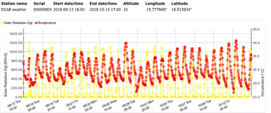
The solar irradiation variations during the experimentation and the ambient temperature variations are depicted and illustrated in Figure 4. The solar irradiation variations were in the range between 800 and 1200 W/m2, with an average value of about 920 W/m2. The ambient temperature is influencing the radiation and convective heat loss from the top surface of the photovoltaic panel.
During experimentation, the ambient temperature was varied between 21°C to about 41°C, with an average value of about 29.2°C. Similar ambient temperature variations were observed.
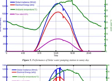
A Figures 5 and 6 show the performance of the stations during a sunny day and cloudy day. The maximum global irradiance was 1300 W/m2 (sunny day) and 1200 W/m2 (cloudy day).
The maximum temperature of the PV module was 45°C Figure 5 (sunny day), and 33°C Figure 6 (cloudy day).
Figures 5 and 6 show the performance of the station during
a sunny day, and cloudy day. The maximum of the electrical energy during the day was 1100 Wh/day (sunny day), and 1000 wh/day (cloudy day).
Final, Figures 5 and 6 show the result of the variations of the water flow rate, the maximum 10 m3/h (sunny day), and 5 m3/h (cloudy day).
Figure 5. Performance of Solar water pumping station in sunny day.
Figure 6. Performance of solar water pumping station in cloudy day.
The simulations are developed to obtain the models parameters applied to pump motor. It is necessary to physically separate the pump motor to develop in the rest of this work, simulations of current-voltage characteristics I (V) and the power-flow P (Q). For each head, we obtained two measured curves: the I-V and the P-Q relationship of the motor pump.
Figure 7 illustrates an example of the characteristics obtained for the pump centrifugal using the experimental measurement. which represent the dependence of the current versus to the voltage for each head. From the result, we found a simple mathematical expression, which allows us to adjust the exprimental value. In the case of the current versus, the voltage, it is linear equation.
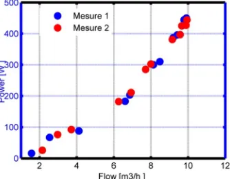
The P(Q) charateristics of the one tested subsystem are carried out and plottes for each total head.
An example of the measurement values are shown in Figure 8. This represents the dependence of the electrical power, P versus to the flow rate, Q the analysis a simple mathematical mode.
Figures 9 and 10 show an example of the experimental values obtained for one head. Thus to define the I-V and P-Q characteristics, we need to solve of a linear equations.
pump head. As shown in Figures 9 and 10 the curves agree very well.
Figure 7. Characteristics current–voltage for pump for different heads.
Figure 8. Characteristics Electrical power - flow rate for pump for different heads.
Figure 9. Characteristics current–voltage curve model validation.
Figure 10. Characteristics Electrical power - flow rate curve model validation.
5. Conclusions
In this research a PV water pumping system in Mauritania climate has been designed. A case study for a small farm in the Higher Institute Technological Education (ISET- Rosso) was selected and discussed. This system is suitable for many rural zones since it’s designed to work with free cost and doesn’t need maintenance. The modelization and the validation of the models of the PV array and the PV pumping subsystem, allow us to simulate the performance of the PV pumping systems for several sites. The analytical model has given a great adjustment of the I-V electrical characteristic curves of the PV array versus solare irradiance and ambiante temperature. Concerning the pumping subsystems, the model for current-voltage and power-flow of PV array is found to agree with experimental curves. The development of the one motor-pump unit models allows us to obtain the operating point of the system and the pumped flow rate. The one model is based on experimental result of several photovoltaic pumps, which have been characterized completely in the pumping test facility to obtain the parameter of the model. The models are established for centrifugal pump (Lorentz ps1200 c-sj8-5) with DC motor.
References
[1] K. Meah, S. Fletcher, S. Ula, Solar photovoltaic water pumping for remote locations, Renew. Sustain. Energy Rev. 2008. [2] J. H. Eckstein, ''Detailed Modelling of Photovoltaic System
Components’, MS Thesis, Mechanical Engineering'', University of Wisconsin, Madison, 1990.
[3] A. A. Ghoneim, ''Design optimization of photovoltaic powered water pumping systems'', Energy Convers. Manag. 2006. [4] B. G. Belgacem, Performance of submersible PV water
pumping systems in Tunisia, Energy Sustain. Dev. 2012. [5] A. Hamidat and B. Benyoucef, ''Mathematic Models of
Photovoltaic Motor-Pump Systems'', Renewable Energy, Mai 2008.
[6] B. Yesilata and Z. A. Firatoglu, Effect of solar radiation correlations on system sizing: PV pumping case, Renew. Energy. 2018.
[7] Chueco-Fernandez Francisco J, Bayod-Rujula Angel A. ‘'Power supply for pumping systems in northern Chile: photovoltaic as alternative to grid extension and diesel engines'' Renew. Energy 2010.
[8] A. Al-Badi, H. Yousef, T. ''Sizing and modelling of photovoltaic water pumping system'', University, Muscat, Sultanate of Oman, INTERNATIONAL JOURNAL OF SUSTAINABLE ENERGY, 2017.
[10] Abdellahi Ba et al, “Performance Optimisation of the PV pumping system”, Procedia Manufacturing, 2018.
[11] F. B. Pelap, P. D. Dongo, A. D. Kapim, ''Optimization of the characteristics of the PV cells using nonlinear electronic components'', Sustain. Energy Technol. Assess, 2016.
[12] A. Hadj Arab, M. Benghanem and F. ''Motor-Pump System Modelization'', Renewable Energy, Juin 2006.
[13] Kou, Q, Klein, S. A, Beckam, Q, A. ''A methode for estimating the long-term performance of direct-coupled PV pumping systems'' Sol. Energy 64, 33-40. 1998.
[14] Hamidat et al, ''Mathematic models of photovoltaic motor-pump systems'', Renewable Energy 33, 2008.
[15] A. Mohammedi, N. Mezzai, D. Rekioua, T. Rekioua, Impact of shadow on the performances of a domestic photovoltaic pumping system incorporating an MPPT control: A case study in Bejaia, North Algeria, Energy Convers. Manag. 84 (2014) 20–29.
[16] Mahmoud, M. E. M., Soukeyna, M., Yahfdhou, A., Mahmoud, A. K. and Youm, I. 2019. Sizing Method of a Storage System for Determining the Performance of a Photovoltaic Pumping System over the Sun. Smart Grid and Renewable Energy, 10: 17-28.