Article
1
Mechanical Properties of Innovative Multi-layer
2
Composite Laminated Panels
3
Jan Niederwestberg 1, Jianhui Zhou 1,2*, Ying Hei Chui 1
4
1 Department of Civil and Environmental Engineering, University of Alberta, Edmonton, T6G 1H9, Canada
5
2 Integrated Wood Engineering, University of Northern British Columbia, Prince George, V2L 1R6, Canada
6
* Correspondence: [email protected]
7
8
Abstract: Cross-laminated timber (CLT) possesses both good shape stability and the possible
two-9
way force transfer ability due to its crosswise lamination. However, the transverse layers in CLT are
10
prone to rolling shear failure under an out-of-plane load. An innovative multi-layer composite
11
laminated panel (CLP) was developed by combining structural composite lumber (SCL) and
12
dimension lumber to overcome the rolling shear failure while maintaining high mechanical
13
performance and aesthetic appearance of natural wood. The mechanical properties of 5-layer CLP
14
consisted of laminated strand lumber (LSL) and dimension lumber with different layups were
15
evaluated by both static and modal tests. The results showed that the shear resistance, bending
16
stiffness and moment resistance of CLP were up to 143%, 43% and 87% higher than their
17
counterparts of regular CLT, respectively. The failure modes observed in both shear and bending
18
tests indicated that the use of LSL in transverse layers could eliminate the potential rolling shear
19
failure in CLT. With the lamination properties from components tests as inputs, the validity of shear
20
analogy method was assessed by test results. The mechanical properties can be well predicted by
21
shear analogy method except for the bending moment resistance of CLP and CLT with either rolling
22
failure in the cross layer or tension failure in the bottom layer.
23
Keywords: cross-laminated timber; structural composite lumber; hybrid; bending properties; shear
24
properties
25
26
1. Introduction
27
Mass timber is an emerging building material that has gained popularity worldwide with the
28
development of mass timber construction in recent years. Mass timber panels (MTPs) are often
29
referred to as panelized engineered wood products of a large dimension and cross section. MTPs
30
cover a broad range of wood products from the well-known traditional parallel laminated elements
31
including glued-laminated timber (GLT), nail-laminated timber (NLT) and dowel-laminated timber
32
(DLT) to the popular cross-laminated timber (CLT) and structural composite lumber (SCL). GLT,
33
NLT and DLT are manufactured by edge-gluing, nail-jointing and dowel-jointing lumber planks with
34
the wood grain of all planks aligned in the same direction, respectively. They are often used as
one-35
way floor slabs in a mass timber construction. CLT is made from graded sawn lumber planks that are
36
orthogonally glued together with a structural adhesive. Due to the orthogonal layer arrangement,
37
CLT has the benefit of resisting out-of-plane loading through the two-way action of the panel plane.
38
However, since the cross-layers with a radial-tangential cross section have a relatively low shear
39
strength and modulus, CLT panels are prone to rolling shear failures when exposed to shear stress
40
perpendicular to the grain as well as excessive deflection under out-of-plane load. In addition,
edge-41
gluing is not mandatory in CLT production [1]. The gaps in the non-edge-glued CLT panels not only
42
can reduce the mechanical properties such as in-plane shear strength and modulus [2-3] but also are
43
unfavourable to fire and building physics considerations. SCL is an important category of engineered
44
wood product in North America, which includes laminated veneer lumber (LVL), laminated strand
45
lumber (LSL), oriented strand lumber (OSL) and parallel strand lumber (PSL). These products are
46
already marketed in structural lumber dimensions in North America for a long time before the advent
47
of mass timber panel construction. In fact, SCL is often produced in massive panel size known as
48
billets before being machined into primarily beam-like members. Generally SCL has great potential
49
for two-dimensional load transfer ability and superior mechanical properties. The North American
50
standard for performance-rated CLT [4] allows for the use of SCL in producing CLT. Therefore,
51
attempts were made to modify generic CLT with SCL to overcome the drawbacks of CLT such as the
52
rolling shear issues and gaps of non-edge glued layers. Three-layer hybrid CLT (HCLT) made from
53
spruce-pine-fir (SPF) and LSL were reported in [5-6]. The bending modulus and strength of HCLT
54
with LSL as outer layers were 19% and 36% higher than those of CLT, respectively [5]. In [6], the
55
HCLT with LSL as core layer showed a 23% higher mean bending stress at failure and a 46% higher
56
mean shear strength than the corresponding values of CLT respectively. Both studies indicated that
57
the rolling shear failure was mitigated by using LSL as the core layer. It should be noted that the LSL
58
used in [6] were of the same size of regular dimension lumber, which did not utilize the advantage
59
of LSL as a panel product.
60
Recently, comprehensive research has been conducted to develop an innovative multi-layer
61
composite laminated panel (CLP) using graded sawn lumber and SCL at the University of New
62
Brunswick [7] and the University of Alberta [8]. Both 3-layer [7] and 5-layer [8] CLP with different
63
layups were produced with different combinations of lumber pieces, LSL and OSL panels. This paper
64
presents the mechanical properties of 5-layer CLPs including apparent and effective bending
65
stiffness, moment resistance, shear resistance and stiffness together with the failure modes. The
66
validation of shear analogy method in predicting bending performance of CLPs was also examined
67
with the lamination properties from component tests.
68
2. Materials and Methods
69
2.1. Materials
70
The materials used for fabricating the 5-layer CLPs were dimension lumber planks and full-size
71
LSL panels. The lumber material was # 2 or better grade 2” by 4” SPF with a cross-sectional
72
dimensions of 38 mm x 89 mm and lengths ranging from 2438 mm to 3048 mm. The dimensions of
73
the LSL panels were 2744 mm (length) × 1220 mm (width) ×38 mm (thickness). The mean moisture
74
content (MC) and density of the lumber and LSL were around 7.4 % and 470 kg/m3, 3.4 % and 644
75
kg/m3, respectively.
76
2.2 Component Tests
77
In order to predict and compare the mechanical properties of CLPs with different layups based
78
on their layer properties, test specimens were cut from the raw materials to evaluate the components
79
mechanical properties. The bending properties and the tensile strength (UTS) were evaluated in
80
accordance to [7]. The modulus of elasticity (MOE) and the modulus of rupture (MOR) of all the
81
materials were measured by third-point bending tests with a span-to-depth ratio of 20. The load and
82
displacement were recorded for the calculation of MOE and MOR. The UTS was measured using a
83
Metriguard tension tester with a specimen gauge length of 1.6 m. Moreover, the planar shear
84
modulus and strength in both strength directions of LSL were evaluated according to [9]. The block
85
shear specimens were prepared and tested using a setup consisting of two aluminum plates with
86
steel knife edges. A load was applied to the knife edges which introduced a shear force onto the
87
specimen that was glued between the two aluminum plates. The load and the displacement between
88
the aluminum plates were recorded for the calculation of shear modulus and strength. The material
89
properties measured in this study together with some reference values are summarized in Table 1.
90
Table 1. Summary of the material properties of lumber and LSL
92
Material Index MC (%)
Density (kg/m3)
MOE (MPa)
MOR (MPa)
Shear Modulus
(MPa)
Shear Strength (MPa)
UTS (N/mm2)
// ⊥ // // ⊥ // ⊥ //
Lumber
Count 18 18 38 38 6
Mean 7.4 470 10494 3432 57.4 6563 1204 54 1.55 30.2
COV1 3.1% 6.4% 15.5% 23.9% 20.1%
LSL
Count 22 22 46 46 6 6 6 6 6
Mean 3.4 644 9520 41.7 462 201 3.2 2.1 36.5
COV1 4.7% 6.4% 5.9% 13.1% 14.2% 9.3% 9.2% 7.5% 11.6%
Note: 1 coefficient of variation (COV), 2 based on 1/30 of MOE, 3 based on 1/16 of MOE, 4 based on [10], 5 based
93
on [11].
94
2.3 Panel Manufacturing
95
Before the fabrication of CLPs, the manufacturing parameters were developed based on the
96
bond performance study with different surface treatments of SCL [7-8]. It was found to be sufficient
97
for fabricating CLPs using one-component polyurethane (PU) adhesive with a spread rate of 32 g/m2
98
under cold press with a pressure of 1.38 N/mm2 for 2 hours. The lumber planks were planed to
99
provide a clean and smooth glue surface as required in the North American standard for performance
100
rated CLT [4]. Seven symmetrical layups of lumber-LSL and all lumber combinations were produced
101
as illustrated in Figure 1. Butt joints were introduced in the middle of the panel in the second and
102
fourth LSL layers for group 5-A1a and the third layer for group 5-A1b. It was intended to evaluate
103
the effect of butt joints on the mechanical properties of CLP since edge gluing is not appropriate to
104
SCL panels in the manufacture practice. A butt joint can be seen in Figure 2. After pressing and
105
trimming, the final dimensions of the 5-layer panels were about 2743 mm in length, 1219 mm in width
106
and 184 mm in thickness.
107
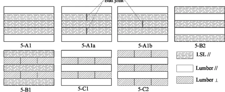
108
Figure 1. Cross sections of HCLT in the length direction with different layups
109
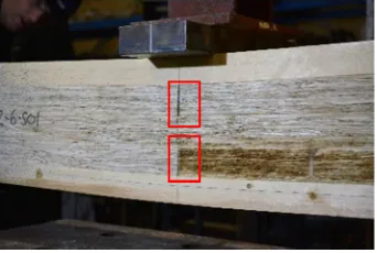
111
Figure 2. A 5-A1a beam specimen with butt joints in the second and fourth layers
112
Table 1 provides the information on the panel layup, the layer orientation and the number of
113
replicates for bending and shear tests. Within the layup column, “T” stands for timber and “L” stands
114
for LSL. In the layer orientation column “//” indicates that the major strength direction of the layer
115
was orientated parallel to the long side of the panel while “⊥” indicates that the minor strength
116
direction of the layer was orientated parallel to the long side of the panel. A total of 17 lumber-LSL
117
CLPs and two generic CLT panels as reference were produced. The CLT panels produced in this
118
study can be assigned as V2 grade CLT in [4] according to the lumber species and stress grade. Beam
119
elements were cut from the CLP and CLT panels.
120
Table 2. Layup information of the panels and number of specimens for mechanical tests
121
Group
ID Layup Orientation
Number of Panels
Bending specimens Shear specimens Dimension Count Dimension Count 5-A1 T-L-L-L-T //-//-//-//-// 3
2743 mm (length) × 195 mm (width) ×
184 mm (thickness)
13
1200 mm (length) × 195 mm (width) ×
184 mm (thickness)
8
5-A1a T-L*-L-L*-T //-//*-//-//*-// 4 16 8
5-A1b T-L-L*-L-T //-//-//*-//-// 4 14 8
5-B1 L-T-L-T-L //-
⊥
-//-⊥
-//3
12 6
5-B2 L-T-L-T-L //-//-//-//-// 3 14 6
5-C1 T-T-T-T-T //-
⊥
-//-⊥
-//1
4 2
5-C2 T-T-T-T-T
⊥
-//-⊥
⊥
-//- 1 4 2Note: * Layer contained a centred butt joint.
122
2.3 Modal Tests
123
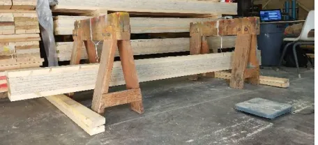
Modal test of each bending specimen was conducted under a free-free boundary condition by
124
suspending the beam with two elastic ropes attached to a rigid frame shown in Figure 3. The first and
125
second natural frequencies of each beam specimen were measured by an impact vibration system
126
consisting of an accelerometer, an instrumented impact hammer, a data acquisition device and
127
experimental modal analysis software. The natural frequencies were used to calculate its dynamic
128
apparent bending stiffness (
EI
app d, ) based on Euler beam theory [12] as well as its dynamic effective129
bending stiffness (
EI
eff d, ) and shear stiffness (GA
eff d, ) based on Timoshenko beam theory [13]. The130
dynamic apparent bending stiffness can be calculated by
131
2 2 4 4
,
4
1/ (
1)
app d
EI
f
Al
l
(1)where
f
1 is the fundamental natural frequency;
is the density;A
is the cross-sectional area;132
l
is the length of the beam;
1l
equals 4.73 according to [12].The dynamic effective bending stiffness and shear stiffness can be determined with the first and
134
second natural frequencies using the method presented in [13]. These two terms are defined as
135
,
eff d gross
EI
EI
(2),
eff d gross
GA
kGA
(3)where
I
grossandA
grossare the gross moment of inertia and cross-sectional area of the beam,k
is the136
shear correction factor.
137
Since the shear correction factor of a laminated composite such as CLT and CLP is dependent
138
on its layup and the properties of laminates [14], the effective shear stiffness is defined as
kGA
grossto139
avoid ambiguity.
140
141
Figure 3. A beam specimen under modal testing
142
2.4 Static Tests
143
2.4.1 Short-span Shear Tests
144
The specimens were tested in short-span shear tests as recommended in [4]. The standard for
145
performance rated CLT recommends an on-centre span equal to 5 to 6 times the specimen depth. The
146
failure load and failure modes were recorded. The test span was at 1000mm (span-to-depth ratio =
147
5.5). The tests were undertaken at a displacement rate of 2 mm/min. The shear resistance from static
148
tests,
V
r s, , can be calculated by149
, max
/ 2
r s
V
F
(4)where
F
max is the maximum load at shear failure.150
2.4.2 Third-point Bending Tests
151
Then third-point bending tests were performed according to [6]. The test span and displacement
152
rate were 2500 mm (span-to-depth ratio = 13.6) and 4 mm/min, respectively. The failure load, failure
153
mode and the deflection at mid-span were recorded during the test. The apparent bending stiffness (
154
, app s
EI
), moment resistance (M
r s, ) can be calculated by155
2 ,23
1296 app s
EI P L
(5)
max ,
2 3
r s
L
M F (6)
where P
is the slope of the load-displacement response in the linear range from 10-40% of
F
max,156
max
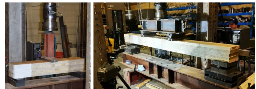
158
159
Figure 4. Short-span shear test setup (left) and third-point bending test setup (right)
160
2.5 Shear Analogy Method
161
Since the shear analogy method has been adopted in the North American CLT product standard
162
ANSI/ APA PRG 320 [4] and in the Canadian timber design code CSA O86 [15] for predicting bending
163
stiffness and shear stiffness of CLT based on mechanical properties of laminations, it is necessary to
164
verify its applicability to the CLP products developed in this study. The effective bending stiffness
165
, eff SA
EI
, shear stiffnessGA
eff SA, , moment resistanceM
r SA. , and shear resistanceV
r SA, can be166
calculated using the following equations,
167
3 2 , 12 n n ieff SA i i i i i
i i
h
EI
E b
E A z (7)2 , 1 1 2 1 1 [ ] 2 2 eff SA
n i n
i
i i n n
a GA
h h
h
G b G b G b
(8) .r SA b eff
M
f S
(9).
,
min
(
)
r SA
vi eff SA i
z
f
EI
b
V
ES
(10)where
E
i is modulus of elasticity of the ith layer;i
b
is the width of the ith layer;i
h
is the thickness168
of the ith layer;
i
A
is the area of cross-section of the ith layer;i
z
is distance from the centroid of the169
ith layer to the neutral axis of the cross-section;
i
G
andf
vi are shear modulus and strength of the170
ith layer, respectively; a is the centroidal distance between top and bottom layers;
eff
S
is the171
effective section modulus,
S
eff
2
EI
eff sa,/
E h
1
;h
is the total thickness;f
b is the bending172
strength of the outer layer;
(
ES
)
zis the static moment at location of z, which is the product of the173
first moment of area and modulus.
174
For a CLP or CLT beam under short-span bending, the shear stress at failure can be calculated
175
by176
. ( ) ,(
)
r s z eff SA
V
ES
EI
b
For a CLP or CLT beam under third-point bending test, the apparent bending stiffness based on
177
shear analogy method,
EI
app sa, , can be calculated by178
,
,
, 2 ,
9.4
1
app SAeff SA
eff SA
eff SA
EI
EI
EI
GA
L
(12)where is the test span of the beam specimen.
179
3. Results and Discussion
180
3.1 Shear Properties
181
The shear properties of all specimens are summarized in Table 3, which includes the shear
182
resistance (
V
r s,) and dynamic shear stiffness (GA
eff d, ) from static and modal tests, respectively, and183
the shear stress at failure (
) and effective shear stiffness (GA
eff SA, ) calculated based on shear analogy184
method. The failure modes are categorized as interfacial shear failure, which is the shear failure in
185
the LSL layer close the glue line, and rolling shear failure, which is the shear failure in the lumber
186
layer perpendicular to grain.
187
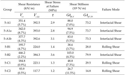
Table 3 Shear properties of 5-layer MTPs
188
Group
Shear Resistance (kN/ m)
Shear Stress at Failure
(MPa)
Shear Stiffness (106 N/ m)
Failure Mode
, r s
V
V
r SA.
GA
eff d,GA
eff SA,5-A1 351.4 392.5 2.9 88.0 73.2 Interfacial Shear
(5.7%) (7.0%)
5-A1a 342.0 393.0 2.8 94.9 73.7 Interfacial Shear
(8.7%) (7.5%)
5-A1b 377.7 392.6 3.1 83.0 73.3 Interfacial Shear
(4.3%) (5.5%)
5-B1 195.7 224.0 1.4 38.6 28.0 Rolling Shear
(4.7%) (3.7%)
5-B2 446.2 384.3 3.6 103.0 79.9 Interfacial Shear
(2.2%) (4.3%)
5-C1 184.8 223.1 1.3 48.8 29.5 Rolling Shear
(0.9%) (7.3%)
5-C2 93.9 117.7 1.2 26.7 14.8 Rolling Shear
(0.5%) (11.5%)
Note: number in brackets is COV; shear resistance and stiffness are based on a panel width of 1 meter.
189
190
As it can be seen in Table 3, the CLP group 5-B2 has the highest shear resistance and stiffness
191
values among all the test groups. CLP groups 5-A1, 5-A1a and 5-A1b have lower shear resistance and
192
stiffness values than the CLP group 5-B2, but higher values than the remaining groups. CLP group
193
5-B1 and CLT group 5-C1 have close shear resistance values due to the same cross layers consisting
194
of lumber pieces, and CLT group 5-C2 has the lowest values as it represents the minor strength
195
direction of a 5-layer CLT panel. The use of LSL in the core layers (5-A1, 5-A1a, and 5-A1b) and
196
longitudinal layers (5-B2) with lumber parallel to grain in the cross layers lead to much higher shear
197
grain in the cross layers (5-B1, 5-C1) or core layer (5-C2). Compared with the major strength direction
199
of a regular CLT (5-C1), the mentioned test CLP groups had up to 142.5% higher shear resistance
200
values (5-A1: 88.9%, 5-A1a: 85.8%, 5-A1b: 102.7%, and 5-B2: 142.5%) and up to 111.1% higher dynamic
201
effective shear stiffness (5-A1: 80.3%, 5-A1a: 94.5%, 5-A1b: 70.1%, and 5-B2: 111.1%). This is due to
202
the difference in planar shear properties between LSL and lumber. The mean planar (rolling) shear
203
strength and modulus of No. 2 grade 2” by 4” western SPF lumber was reported to be 1.5 MPa and
204
73 MPa, respectively [10], while the mean planar shear strength and modulus of the LSL parallel to
205
grain was measured to be 3.2 MPa and 462 MPa, respectively. Therefore, as expected, the calculated
206
shear stress at failure in Table 3 agree well with the shear strength properties of the material that
207
failed in the tests.
208
As shown in Figure 5, the measured shear resistances agree well with calculated counterparts
209
for each group if the variation of wood material properties is taken into account. The difference
210
between measured and calculated shear resistances varied from -12.7% to +25.4% (5-A1: 9.8% higher,
211
5-A1a: 13.0% higher, 5-A1b: 2.2% higher, 5-B1: 14.6% higher, 5-B2: 12.7% smaller, 5-C1: 20.7% higher,
212
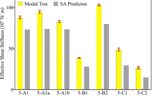
and 5-C2: 25.4% higher). The effective shear stiffness values of both CLP and CLT measured by modal
213
tests are generally higher than those calculated by shear analogy method, though a mean rolling shear
214
modulus of 120 MPa for lumber was used for the calculation. The difference between the
215
measurement and prediction effective shear stiffness values are between 11.7% and 44.6% (5-A1:
216
16.8% higher, A1a: 22.3% higher, A1b: 11.7% higher, B1: 27.5% higher, B2: 22.4% smaller,
5-217
C1: 39.5% higher, and 5-C2: 44.6% higher). It is thought that the effective shear stiffness is
under-218
estimated by the shear analogy method, especially for dynamic applications.
219
220
Figure 5. Comparison between measured and calculated shear resistance values
221
222
The failure modes observed during the short span shear tests are shown in Figure 7. As
224
mentioned, typical rolling shear failures were found in the three groups with lumber perpendicular
225
to grain as cross layers (5-B1, 5-C1, 5-C2) and the interfacial glue bond failure was observed in the
226
other groups. Moreover, tension failures were noted for 5-A1 and 5-A1a groups (5-A1: 1 tension and
227
5 interfacial shear failures, A1a: 2 tension and 4 interfacial shear failure failures). Within group
5-228
B2 one tension failure were recorded, the other five specimen failed due to interfacial shear failure.
229
230
Figure 7. Typical failure modes under short-span bending (shear) tests
231
3.2 Bending Properties
232
The bending properties including moment resistance and bending stiffness values obtained from
233
both measurements and predictions are listed in Table 4. The failure modes are categorized as tension
234
failure of the bottom layer of MTPs, and rolling shear, which is the shear failure in the cross lumber
235
layer.
236
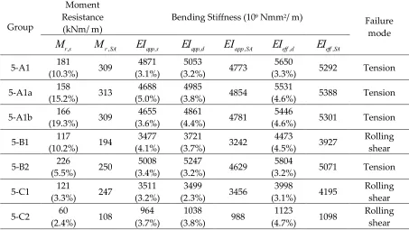
Table 4 Bending properties of 5-layer MTPs
237
Group
Moment Resistance
(kNm/ m)
Bending Stiffness (109 Nmm2/ m)
Failure mode
, r s
M
M
r SA,EI
app s,EI
app d,EI
app SA,EI
eff d,EI
eff SA,5-A1 181 309 4871 5053 4773 5650 5292 Tension
(10.3%) (3.1%) (3.2%) (3.3%)
5-A1a 158 313 4688 4985 4854 5531 5388 Tension
(15.2%) (5.0%) (3.8%) (4.6%)
5-A1b 166 309 4655 4861 4781 5446 5301 Tension
(19.3%) (3.6%) (4.4%) (4.6%)
5-B1 117 194 3477 3721 3242 4473 3927 Rolling
shear
(10.2%) (4.1%) (3.7%) (4.5%)
5-B2 226 250 5008 5247 4629 5804 5071 Tension
(5.5%) (3.4%) (3.2%) (3.2%)
5-C1 121 247 3511 3499 3456 3998 4195 Rolling
shear
(3.3%) (3.2%) (2.3%) (3.1%)
5-C2 60 108 964 1038 988 1123 1098 Rolling
shear
(2.4%) (3.7%) (3.8%) (4.7%)
Note: The values in the brackets are the coefficient of variation.
238
As seen in Table 4, similar to the trend in shear properties, the measured bending properties of
239
CLP group 5-B2 outperform other MTP groups, especially for the bending moment resistance. The
240
MPa) compared with lumber (30.2 MPa). Compared with the bending test values of CLT (5-C1), CLP
242
groups 5-A1, 5-A1a, 5-A1b and 5-B2 with LSL layers parallel to the length direction of the beam show
243
increased bending moment resistance and apparent bending stiffness values to different extents
(5-244
A1: 49.6% & 38.7%, 5-A1a: 30.6% & 33.5%, 5-A1b: 37.2% & 32.6% and 5-B2: 86.8% & 42.6%). CLP group
245
5-B1 shows very similar values to CLT (5-C1). The increase is due to two reasons. First, LSL has higher
246
shear strength and modulus in the parallel to grain direction than the rolling shear strength and
247
modulus of lumber although the MOE of LSL and lumber used in this study are close to each other.
248
Second, all the longitudinal and transverse layers in CLP groups of 5-A1, 5-A1a, 5-A1b and 5-B2 have
249
laminations parallel to gain. The intended parallel orientation of all layers can increase the allowable
250
span if such products are used as one-way floor systems. Moreover, due to the high bending and
251
shear properties of SCL in the minor strength direction, two-way mechanical behaviour can also be
252
achieved for 5-layer CLP.
253
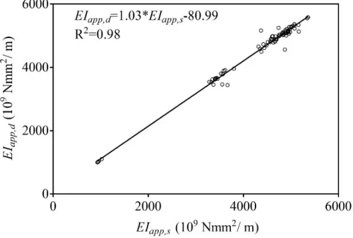
The apparent bending stiffness measured by modal tests agree well with the values obtained
254
from static bending tests with a mean difference less than 7.7%. The good correlation between the
255
values measured by both methods is illustrated in Figure 8. Thus, the modal test can be used as an
256
alternative method to evaluate the apparent bending stiffness of MTP beam specimens. The apparent
257
bending stiffness based on Euler beam theory includes the effect of shear deformation, while the
258
evaluated effective bending stiffness based on Timoshenko beam theory does not, which enable the
259
separation of effective shear stiffness and the verification of effective bending stiffness calculated by
260
shear analogy method. The effective bending stiffness obtained from modal tests are between 8.2%
261
to 20.2% higher than the apparent bending stiffness obtained from modal tests depending on the
262
layups of MTPs. The effective bending stiffness and shear stiffness obtained by modal test can be
263
used for applications where the transverse shear deformation should be accounted, or the natural
264
frequencies of higher vibration modes are of interest.
265
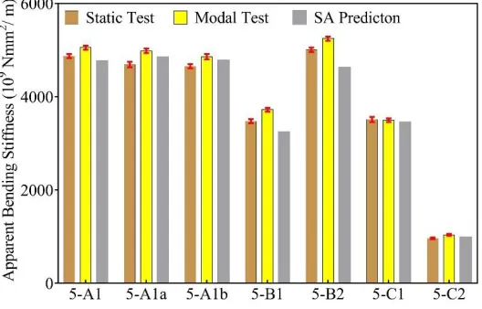
266
267
Figure 8. Correlation of apparent bending stiffness measured by modal and static tests
268
The comparison among static bending tests, modal tests and shear analogy predictions are
269
presented in Figure 9-11. The shear analogy method predicts lower but close apparent and effective
270
bending stiffness values and much higher moment resistance values than their measured
271
counterparts. As shown in Figure 9, except for CLP group 5-B2, all groups have a much smaller
272
measured moment resistance value than its predicted value. It should be noted that the bending
273
strength values of LSL and lumber were used for the calculation of moment resistance in Eq. 9.
274
However, for 5-B1, 5-C1 and 5-C2, they had rolling shear failure in the cross layers. It is no wonder
275
that the predicted moment resistance values are much higher than their measured ones. For 5-A1
276
series and 5-B2, the discrepancies can be explained by the increased uniformity of tensile stress
277
distribution in the bottom layer. For a 5-layer layup where all layers have the same thickness, the
278
trapezoid stress distribution in the layer. Therefore the specimens have a higher possibility of tension
280
failure in the layer when the stress level exceeds the tensile strength of the material rather than
281
bending strength, which is usually governed by the tensile strength of the outmost fibres. Moreover,
282
the bending strength of wood materials is known to be higher than its tensile strength if the test
283
specimen is of structural size. The average bending and tensile strength values are 56.2 MPa and 30.2
284
MPa for lumber, 43.2 MPa and 36.5 MPa for LSL, respectively. The average bending to tensile strength
285
ratios in this study are 1.86 for lumber and 1.18 for LSL respectively. Therefore, the calculated
286
moment capacity based on bending strength is higher than measured. It can also be seen that the CLP
287
group 5-B2 with tension failure in LSL bottom layers has smaller differences between measured and
288
calculated moment capacity values due to the smaller bending to tensile strength ratio than that of
289
lumber.
290
291
Figure 9. Average moment capacity of 5-layer MTPs by bending test and shear analogy method
292
293
Figure 10. Apparent bending stiffness of 5-layer MTPs by bending test, modal test and shear analogy
294
296
Figure 11. Effective bending stiffness of 5-layer MTPs by modal test and shear analogy method
297
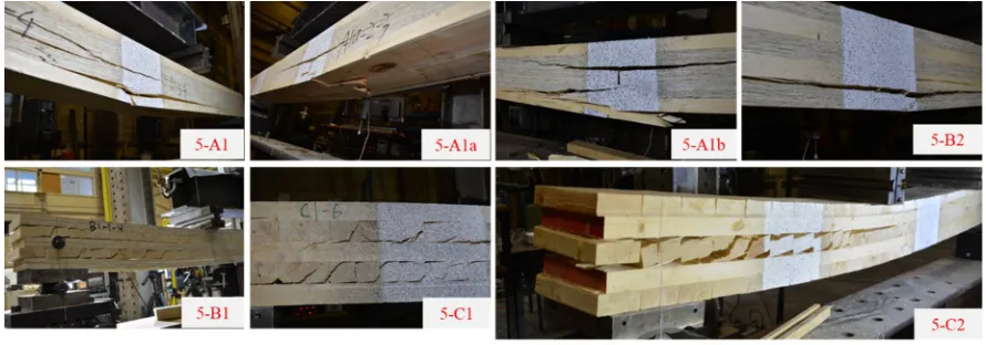
The typical failure modes of all the 5-layer MTP specimens are presented in Figure 12. Simple
298
tension failure in the bottom layer of lumber was observed in groups 5-A1, 5-A1a and 5-Ab, in
299
particular around a knot. Simple tension failure in the bottom layer of LSL was seen in group 5-B2.
300
Interfacial shear failure was the secondary failure after tension in the groups mentioned above. There
301
was also no primary shear failure in the cross layers in the groups mentioned above. Typical rolling
302
shear failure was found in the lumber cross layers in groups 5-B1, 5-C1 and 5-C2. No mixed failure
303
modes were found within each group.
304
305
Figure 12. Typical failure modes under third-point bending tests
306
3.3 Effect of layup and butt joint on the mechanical properties of CLP
307
The five CLP groups can be divided into three types based on their layups, the 5-A series (5-A1,
308
5-A1a and 5-A1b), 5-B1 and 5-B2. With the mechanical properties of five groups of CLP presented in
309
the above sections, it is evident that 5-B1 has the lowest mechanical properties values due to the cross
310
layers of lumber perpendicular to grain. However, the 5-A series and 5-B2 both have their
311
advantages. The 5-A series have no gaps in the middle layers (not counting the butt joints) and surface
312
layers with lumber appearance. They can avoid rolling shear failure if both strength directions are
313
considered. The 5-B2 group has slightly better mechanical performance in the major strength
314
direction but would have rolling shear failure if the minor strength direction is considered. Future
315
research should investigate the two-way behaviour of both types.
316
It seems that the presence of butt joints has little influence on the mechanical properties of 5-A
317
series based on the mean values listed in Table 3 and 4. One-way ANOVA analysis was conducted
318
regarding shear resistance, moment resistance and apparent bending from bending tests for further
319
apparent bending stiffness were 0.64, 0.085 and 0.015, respectively, which indicated the significance
321
levels of the three parameters in 5-A1, 5-A1a, 5-A1b. It is safe to conclude that the effect of butt joints
322
on shear and moment resistance is negligible, while a significant difference is found among the
323
apparent bending stiffness values among the three groups. A further Tukey pairwise comparison
324
indicated that apparent bending stiffness of 5-A1 was significantly different from the other two
325
groups. The different positions of butt joints between 5-A1a and 5-A1b did not influence their
326
bending stiffness. But the influence of butt joints can be affected by their spacing and may need to be
327
further investigated. It might be beneficial to achieve slightly better bending performance by
328
avoiding butt joints during fabrication.
329
4. Conclusions
330
A new category of mass timber panel designated as composite laminated panel (CLP) has been
331
developed in this study. The mechanical properties of the CLP were evaluated through both static
332
bending and modal tests. The applicability of shear analogy method to predicting the mechanical
333
performance of CLP was also examined. The following findings can be concluded.
334
1) The use of LSL as transverse layers in CLP can eliminate the typical rolling shear failure of CLT
335
and increase the shear resistance and stiffness, bending moment resistance and stiffness
336
compared with generic CLT.
337
2) The CLP with LSL and lumber being parallel to grain in all layers performs the best among all
338
the CLP lay-ups investigated in this study.
339
3) The shear analogy method can be used to predict mechanical performance of CLP including
340
stresses at failure, effective bending and shear stiffness, and apparent bending stiffness.
341
However, the prediction of moment resistance depends on actual failure mode and the related
342
material strength values.
343
4) Modal test is effective in measuring the bending and shear stiffness of MTP with a good
344
agreement with static test results.
345
Author Contributions: Conceptualization, Y.C..; Methodology, J.Z. and J.N.; Validation, J.Z. and J.N.; Formal
346
Analysis, J.Z. and J.N..; Investigation, J.Z. and J.N.; Resources, Y.C.; Data Curation, J.N.; Writing-Original Draft
347
Preparation, J.Z.; Writing-Review & Editing, J.N and Y.C..; Visualization, J.Z.; Supervision, Y.C.; Project
348
Administration, Y.C.; Funding Acquisition, Y.C.
349
Funding: This research was funded by Natural Sciences and Engineering Research Council of Canada Industrial
350
Research Chair in Engineered Wood and Building Systems program grant number [IRC500897-16] and Alberta
351
Innovates [BFR-016-002].
352
Acknowledgments: In-kind support from Tolko Industries Ltd and Henkel is acknowledged.
353
Conflicts of Interest: The authors declare no conflict of interest.
354
References
355
1. Brandner, R.; Flatscher, G.; Ringhofer, A.; Schickhofer, G.; Thiel, A. Cross laminated timber (CLT):
356
overview and development. European Journal of Wood and Wood Products 2016, 74, 331-351.
357
2. Zhou, J.; Chui, Y. H.; Gong, M.; Hu, L. Elastic properties of full-size mass timber panels: Characterization
358
using modal testing and comparison with model predictions. Composite Part B: Engineering 2017, 112,
203-359
212.
360
3. Brandner, R.; Dietsch, P.; Dröscher, J.; Schulte-Wrede, M.; Kreuzinger, H.; Sieder, M. Cross laminated
361
timber (CLT) diaphragms under shear: Test configuration, properties and design. Construction and Building
362
Materials 2017, 147, 312-327.
363
4. APA – The Engineered Wood Association. Standard for Performance-Rated Cross-Laminated Timber;
364
ANSI/APA PRG 320; APA – The Engineered Wood Association, Tocama, WA, USA, 2018.
365
5. Wang, Z.; Gong, M.; Chui, Y. H. Mechanical properties of laminated strand lumber and hybrid
cross-366
laminated timber. Construction and Building Materials 2015, 101, 622-627.
367
6. Davids, W. G., et al. Structural performance of hybrid SPFs-LSL cross-laminated timber panels. Construction
368
7. Chui, Y. H.; Gong, M.; Niederwestberg, J. Development of a lumber-SCL massive timber panel product. Final
370
Report #: WSTC2014-038, Wood Science and Technology Centre, the University of New Brunswick,
371
Fredericton, NB, Canada, 2015.
372
8. Zhou, J.; Niederwestberg, J.; Chui, Y. H. Development and Evaluation of 5-layer Lumber-SCL Massive
373
Timber Panel. Final Report, the University of Alberta, Edmonton, AB, Canada, 2017.
374
9. ASTM. Standard Test Methods of Static Tests of Lumber in Structural Sizes; ASTM D198; ASTM International,
375
West Conshohocken, PA, USA, 2010.
376
10. ASTM. Standard Test Methods for Structural Panels in Planar Shear (Rolling Shear); ASTM D2718; ASTM
377
International, West Conshohocken, PA, USA, 2006.
378
11. Chui, Y. H.; Gong, M. Evaluation of planar shear properties of cross layer in massive timber panel. Final Report #:
379
WSTC2013-015, Wood Science and Technology Centre, the University of New Brunswick, Fredericton, NB,
380
Canada, 2015.
381
12. Yee, H. W. Shear strength of Canadian softwood structural lumber. Master Thesis, the University of British
382
Columbia, Vancouver, Canada, 1995.
383
13. Inman, D. J. Engineering vibration, 4th ed.; Prentice Hall, New Jersey, 2008; pp. 538–540, ISBN
978-0-13-384
287169-3.
385
14. Chui, Y. H. Simultaneous Evaluation of Bending and Shear Moduli of Wood and the Influence of Knots on
386
these Parameters. Wood and Fibre Science 1991, 25, 125-134.
387
15. Bogensperger, T.; Silly, G.; Schickhofer, G.. Methodenvergleich approximativer Nachweisverfahren für
388
Brettsperrholz. Report #: MMSM 2.2.3 sfem_mat, holz.bau forschungs GmbH, Institut für Holzbau und
389
Holztechnologie, Technische Universität Graz, Graz, Austria, 2012.
390