Article
Development of Sliding Mode Controller for A
Modified Boost Cuk Converter Configuration
Sanjeevikumar Padmanaban 1,*, Emre Ozsoy 1, Viliam Fedák 2
1 Department of Electrical and Electronics Engineering, University of Johannesburg, Auckland Park, South Africa; [email protected], [email protected]
2 Department of Electrical Engineering & Mechatronics, Technical University of Kosice, Rampová 1731/7, 040 01 Košice - Džungľa-Džungľa, Slovakia; [email protected]
*Correspondence [email protected]; Tel.: +27-79-219-9845
Abstract: This paper introduces a sliding mode control (SMC) based equivalent control method to a novel high output gain Cuk converter. An additional inductor and capacitor improves the efficiency and output gain of the classical Cuk converter. Classical PI controllers are widely used in DC-DC converters. However, it is a very challenging task to design a single PI controller operating in different load and disturbances. SMC based equivalent control method which achieves a robust operation in a wide operation range is also proposed. Switching frequency is kept constant in appropriate interval in different loading and disturbance conditions by implementing a dynamic hysteresis control method. Numerical simulations conducted on Matlab/Simulink confirm the accuracy of analytical analysis of high output gain modified Cuk converter. In addition, proposed equivalent control method is validated in different perturbations to demonstrate the robust operation in wide operation range.
Keywords: Closed Loop Control; Cuk Converter; Sliding Mode Control; Robustness; Active Hysterisis Control
PACS: J0101
1. Introduction
DC-DC converters play a vital role in electrical systems due to increasing penetration of renewable sources in electrical networks. In addition to high efficiency and reliability requirements, robust performance of the converter in wide operating range is of great importance, since dc-dc converters are also used in diverse special purpose applications, such as electrical vehicles, dc motor drives and telecommunication systems.
Different DC-DC converter topologies can be encountered in the literature. Classical boost [1] and Cuk converters [2] are commonly used as DC-DC converters which realize the polarity inversion in the output voltage. Single ended primary-inductor converter (SEPIC) [3] is another different type non-inverting buck-boost voltage converter topology. However, these conventional topologies have a limited output voltage gain values due to the effect of parasitic elements, and usually maximum available output voltage gain ratio Vo/Vi is not greater than 9. Higher output
voltage turn ratio with improved efficiency increases the performance of the converter which is crucial for especially solar applications [4]. Diverse DC-DC converter topologies are proposed in [5-7] to improve the voltage turn ratio and efficiency. Important voltage lift methods are reviewed and compared in [8].
A DC-DC converter circuit topology must be upgraded for; higher voltage output gain and improved efficiency, lowering the conduction losses, designing smaller size converter, minimizing voltage and current stress on the semiconductor switch. In addition to circuit modification for
achieving the above goals, controller structure is also of great importance to improve the performance, robustness and reliability in wide operation range. Unfortunately, these converters are still bottleneck in terms of system reliability and performance [4].
High performance control of a DC-DC converter is a challenge for both control engineering and power electronics practitioners due to highly nonlinear nature of DC-DC converters. Furthermore, fast response in terms of rejection of load variations, input voltage disturbances and parameter uncertainties is mandatory for robust operation.
Cuk converter is a kind of buck/boost converter topology; either the inverted output is lower or higher than the input voltage. Different modifications are applied to classical Cuk circuit [9, 10] to enhance the performance. Modeling and control of Cuk Converter have been investigated with different approaches. Linear methods [11, 12] and PI controllers [1] are well known design procedures with ease of implementation. However, these classical methods do not guarantee the stability and high performance in different perturbations due to highly nonlinear behavior of Cuk converter. Thus, different nonlinear control algorithms are also implemented to Cuk converter to overcome this drawback, such as passivity based control [13], neural networks [14], direct control methods [15], fuzzy logic [16] and sliding mode control (SMC) [17].
SMC for variable structure systems [18] is a robust control method of nonlinear systems due to its insensitivity of parameter variations, fast dynamic response and ease of implementation. SMC was first applied to DC-DC converters in [19, 20] and many diverse implementation examples are available in [18]. Design criteria for SMC application to DC-DC converters is outlined in [21]. SMC based equivalent controller is applied to buck-boost and Cuk converter topologies in [22]. However, SMC is not popularly implemented to DC-DC converters due to its unavailability of integrated circuit forms for power electronic applications. Moreover, its variable switching frequency (SF) behavior depending on the converter parameters and operation regions complicates electromagnetic interference filter design and practical implementation. A scheme given in [23] outlines the SF fixing and reduction methods in SMC applications. In addition, it is known that DC-DC converters are unwanted noise generators, and this problem can be overcome with fixed frequency operation [21].
Different control techniques were proposed to achieve constant SF operation to DC-DC converters. An equivalent controller is designed and the output of the controller is compared with saw tooth signal to fix the SF in [24]. Frequency locking techniques are applied in [25] to achieve constant SF operation of SMC for buck converter. An analog circuit design perspective for fixed frequency operation of SMC is given in [26]. Dynamic hysteresis control [27, 28] is another contribution which is commonly used for fixed SF operation.
This study aims to improve the output voltage gain of Cuk converter circuit by inclusion of a single inductor and capacitor. The efficiency of overall system is increased, and it is verified that voltage transformation ratio (vo/vi) is increased to 1/(1- δ), just as classical boost converters, where δ
is the duty ratio of the converter. Proposed model is mathematically analyzed, and numerical
simulations conducted on Matlab/Simulink validate the accuracy of the analysis.
Moreover, a SMC based cascaded equivalent controller is implemented for robust operation of proposed converter. PI controllers are very simple and practical approach for industrial applications. External PI voltage controller achieves the desired output voltage requirements, while inner SMC based equivalent controller performs the control of input current. Therefore, cascaded PI+SMC structure achieves robust operation of novel high output gain Cuk converter in a wide operation range. Constant SF operation is achieved in different loading and disturbance conditions by using a simple dynamic hysteresis controller. The control algorithm is implemented on Matlab/Simulink environment in different scenarios; 1) A high value of output reference voltage step 2) Output resistance variation 3) Input voltage drop 4) Input inductor parameter variation. The proposed method effectively achieves performance goals for all aforementioned perturbations.
2. High Output Gain Modified Cuk Converter
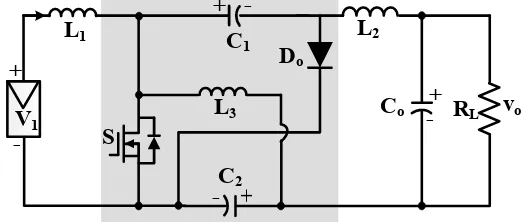
Developed Cuk converter is depicted in Fig. 1. Classical Cuk converter is modified with
representation of the modified Cuk Converter that the semiconductor switch S is turned ON and OFF, respectively.
Figure 1. Topology of proposed novel Cuk DC-DC converter
(a) (b)
Figure 2. Circuit configuration (a) ON state; (b) OFF state
When the switch S is turned ON and OFF the following inductance voltage equations can be written to the circuit over one period for steady state circumstances, respectively. When the S ON;
VL1 = V1, VL2= V0 -VC2- VC1 , VL3 = -VC2 (1)
When the S is OFF;
VL1 = V1 - VC1, VL2 = -Vo + VC2, VL3 =VC1+VC2 (2)
According to Faraday Law, average voltage across an inductor is zero at steady state. Hence, voltage turn ratio of the converter can be obtained by starting the commonly used equation given below.
δ VL(ON) = (1 − δ)VL(OFF (3)
The term δ means the duty ratio of the switch S. Equation (3) will be written for L1, L2 and L3
and required voltage turn ratio equation will be obtained.
First, (3) is written for L1, and the equation given below is obtained;
δ V1 = (1 − δ)(V1 - VC) (4)
The above equation can be simplified as;
(2 δ -1)V1 = (δ -1) VC1 (5)
Second, (3) can be written for L2 as given below;
δ (V0 -VC2- VC1) = (1 − δ)(Vo +VC2) (6)
Equation (6) can be arranged as given below;
V0(2 δ -1)= VC2 + δ VC1 (7)
L
1C
1
+
-L
3C
ov
oD
oV
1+
-
S
+
- R
LC
2+
Finally, (3) can be written for L3;
δVC2 = (1 − δ)(VC1 + VC2) (8)
This simplifies to;
VC2 = (1 − δ)VC1 (9)
If (5), (7) and (9) are combined, duty ratio of the converter can be obtained. If (9) is inserted into (7);
Vo (2 δ -1) = VC1 (10)
If (10) is inserted into (5) duty ratio of the system can be finalized.
= − (11)
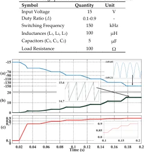
A sample design circuit can be conducted by using the circuit parameters given in table 1 in Matlab/Simulink. Different δ values are applied in simulation as shown in Fig 3c. Output voltage (vo)
and input current (ii) curves change accordingly, as shown in Fig. 3a and 3b, respectively. Output
voltage and input currents are zoomed; it is observed in simulations that the frequency of the ripples is equal to the SF (150 kHz).
Table 1. Design parameters of Modified Cuk Converter
Symbol Quantity Unit
Input Voltage 15 V
Duty Ratio (∆) 0.1-0.9 -
Switching Frequency 150 kHz
Inductances (L1, L2, L3) 100 µH
Capacitors (C0, C1, C2) 5 µF
Load Resistance 100 Ω
Figure 3. Simulation of modified Cuk Converter (a) Output Voltage (V) (b) Input Current (A) (c) δ
(a) (b)
Figure 4. Comparison of Buck-Boost, Cuk and Modified Cuk Converter (a) Duty Ratio (b) Efficiency
3. Equivalent Control of Modified Cuk Converter
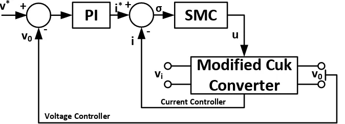
A cascaded PI+SMC controller structure could be used for ease of implementation to modified Cuk converter as depicted in Fig. 5. A simple external voltage controller can generate input current reference, while equivalent controller controls the input current.
Figure 5. Cascaded Control of modified Cuk Converter
Although modified Cuk converter is a third order nonlinear model, input current equation is only required to construct an equivalent controller. This is the main advantage of SMC based equivalent controller, since the performance is independent on all system dynamics and parameter variations. Input current of modified Cuk converter in terms of Kirchhoff voltage law can be written in the following form.
= (v − (1 − u)v ) (12)
The terms, vi and vc1 are input C1 voltages, and u is the switching signal of semiconductor
switch as explained below.
u(t) 10 Switch → ONSwitch → OFF D → OFFD → ON (13)
External PI controller aims to achieve the reference voltage target, and output of the PI controller acts as reference current (i*). Internal SMC based equivalent current controller aims to
track current trajectory, and analytical design procedure is detailed below. The switching surface can be given as;
σ = − ∗ (14)
The time derivative of switching surface is;
σ = − ∗ (15)
If input current equation of modified Cuk converter in (12) is written to derivative of switching surface, following equation can be obtained
+
-+
PI
SMC
Modified Cuk
Converter
u
-Current Controller
Voltage Controller
i
v
0v
0i
*v
iσ = − (1 − u)v − ı∗ (16)
If σ is assumed to be zero at steady state, equivalent control signal can be generated as given below.
= 1 + ∗− (17)
Switching surface can be simplified as given below, considering σ is zero at steady state. Continuous function ueq will be converted into discontinuous form as follows.
σ = u − (18)
Closed loop control signal from switching surface can be given as;
u = − Kσ (19)
The term K is positive definite control gain, and if (19) is inserted in (18), switching surface can be written as follows.
σ = − Kσ − (20)
Where is the estimated equivalent control input. It can be written in steady state that =
σ = −Kσ (21)
Necessary and sufficient condition for Lyapunov stability and existence condition for sliding mode control [18] σσ < 0, and it is satisfied from (21) that;
σ > 0 σ < 0
σ < 0 σ > 0 (22)
Thus, stability of sliding surface is satisfied. Controller structure can be constructed by estimating . Estimation of the equivalent control can be formed as;
ν = + lσ (23)
Where the term l is the filter gain of the estimator. It is assumed that is constant, time derivative of (23) can be written as given below.
v = lσ (24)
Time derivative of σ in (18) can be inserted into (23) as given below.
v = l(u − ) (25)
It can be stated that = in steady state;
v = l(u − ) (26)
If (26) is written in the form of = v − lσ, following equation can be obtained.
v = l(u − v + lσ) (27)
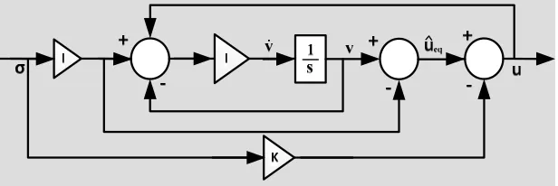
Finally, simple equivalent controller structure in Fig. 6 can be obtained from the definitions written below.
As detailed in [18], Fig. 6 shows that a dynamic system can be formed as a series of integrators, and it can be assumed that the output of this system can be estimated by an upper bound of the integral. Finally, a dynamic relay with hysteresis function as given in Fig. 7 can be applied to control signal to generate a sliding surface which oscillates with the magnitude of M.
Figure 7. Dynamic relay with hysteresis function
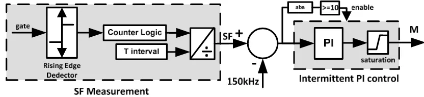
The main disadvantage of SMC based equivalent controller is variable switching frequency (SF), because the magnitude of oscillations in sliding surface is highly dependent on circuit parameters and operating conditions due to nonlinear behavior of the converter. One of the methods that can constrain the sliding surface to constant SF operation can be a dynamic hysteresis controller [27] which dynamically changes the magnitude of sliding surface σ according to desired switching frequency value. An additional PI controller which intermittently operates to bring back the SF to desired value can be a simple and practical solution. Output of PI controller dynamically changes the hysteresis of dynamic relay (M). Thus, SF can settle to a desired interval accordingly. Another drawback of the method is the requirement of the SF measurement. A SF measurement algorithm could be implemented by counting the rising edge of the gate signals at certain instants. If the number of rising signals is divided into predefined time interval, SF can be easily calculated. As a result, an intermittent PI controller structure can keep the SF constant at a specified interval as shown in Fig. 8. The output of intermittent PI controller is the resultant M value of the dynamic relay with hysteresis function.
Figure 8. SF Measurement and intermittent PI controller
3. Simulation Results
Four different scenarios are implemented in a single simulation in Matlab/Simulink SimPowerSystem platform at different time instants. Variable Step Ode23tb (stiff/TR-BDF2) solver is used in simulations. Same circuit parameters are used in simulation as given Table 1. Stable gains for external PI controller and equivalent controller are given in Table 2. Standard Routh-Hurwitz criterion for determination of PI gain values is omitted in this paper, and all gain values are determined using trial-error methods. For further details of Routh-Hurwitz criterion for external PI controller, one can refer to [17]. Target SF value is selected as 150kHz, and intermittent PI hysteresis controller is only enabled, when the absolute value of error exceeds 10 as shown in Fig. 8. It is not possible to realize a precise controller for SF control in all perturbations due to unexpected oscillations in M value.
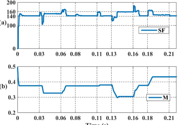
0.08-0.11: Load resistance is decreased from 100Ω to 85Ω (15% load increase) 0.13-0.16: Input voltage is decreased from 15V to 12V (20% input voltage dip) 0.18-0.21: Input inductor (L1) is decreased from 100µH to 100µH (15% L1 reduction)
Table 2. Controller parameters of Modified Cuk Converter
Symbol Quantity
Kp of voltage PI controller 0.001
KI of PI voltage controller 90
Target Switching Frequency 140-160 kHz
K of Equivalent Controller 0.01
L of Equivalent Controller 1
Kp of hysteresis controller 0.00005
KI of hysteresis controller 0.6
Fig. 9 shows the output voltage and input current response at different perturbations. Required trajectories are successfully tracked at all disturbances.
Figure 9. Performance of proposed equivalent controller (a) Output voltage (b) Input Current
Figure 10. Performance of proposed equivalent controller (a) SF (b) M
Figure 11. Output voltage and current ripple transients (a) Gate signal (b) Control Signal (u) (c) Input Current (d) Output Voltage
5. Conclusions
This paper proposed a modified high output gain Cuk converter with a SMC based equivalent controller. The efficiency and performance of Classical Cuk converter is improved by simple inclusion of single inductor and capacitor. Moreover, a constant switching frequency cascaded equivalent controller structure is proposed. Simulation results show the effectiveness and robustness of proposed method, and constant switching frequency approach to SMC based controller provides the opportunity of simple application to real systems.
Acknowledgments: No source of funding for this project.
in the Control Scheme and verification of theoretical concepts and background with obtained results. All authors contributed and involved in framing the full version of the research article in its presented form”.
References
1. Rashid, M.H. Power electronics: circuits, devices, and applications, 2009, Pearson Education India 2. Middlebrook, R.D; S. Cuk. A general unified approach to modeling switching-converter power stages,
1976, Power Electronics Specialists Conference, 1976 IEEE. IEEE.
3.
Restrepo, C; Calvente, J; Cid, A. Aroudi, A; Giral, R. A non-inverting buck-boost dc-dc switching converter with high efficiency and wide bandwidth, in IEEE Trans. Power Electron., vol. 26, no. 9, Sep.2011 pp. 2490–2503.4. Sanjeevikumar,P; Grandi,G; Wheeler,P; Blaabjerg, F; Loncarski, J; A Simple MPPT Algorithm for Novel PV Power Generation system by High Output Voltage DC-DC Boost Converter, Conf. Proc., 24th IEEE Intl. Symp, on Industrial Electronics, 2015, Rio de Janeiro (Brazil), pp. 214–220.
5. Sanjeevikumar, P; Kabalci, E; Iqbal, A; Abu-Rub, H; Ojo, O. Control Strategy and Hardware Implementation for DC-DC Boost Power Conversion Based on Proportional-Integral Compensator for High Voltage Application. Engg. Science and Tech.: An Intl. J. (JESTECH). Elsevier Journal. Pub., 2014 vol. 18,no. 2, pp. 163–170.
6. Mahajan, S.B; Sanjeevikumar, P; Blaabjerg, F; Kulkarni, R; Seshagiri,S; Hajizadeh,A. Novel LY Converter Topologies for High Gain Transfer Ratio- A New Breed of XY Family. 4th IET Intl. Conf. On Clean Energy and Technology, 2016, (IET_CEAT16), Kuala Lumpur, Malaysia.
7. Julio, C; Caro R; Fernando, M; Mayo-Maldonado, J; Miguel, J; Halida L; Jejus E. Transformer-less high gain boost converter with input current ripple cancelation at a selectable duty cycle. IEEE trans. industrial electronics vol 60, issue 10, PP. 4492-4499, 2013.
8. Li, C.W; and He, X; Review of non-isolated high step-up DC/DC converters in photovoltaic grid-connected applications, IEEE Trans. Ind.Electron., April 2011, vol. 58, no. 4, pp. 1239–1250.
9. Zhu, M; Luo, F.L; Enhanced self-lift Cuk converter for negative-topositive voltage conversion, IEEE Trans. Power Electron., Sep. 2010, vol. 25, no. 9, pp. 2227–2233.
10. A. J. Sabzali, E. H. Ismail, M. A. Al-Saffar, and A. A. Fardoun, “New bridgeless DCM Sepic and Cuk PFC rectifiers with low conduction and switching losses,” IEEE Trans. Ind. Appl., vol. 47, no. 2, pp. 873–881. 11. Cuk, S; Middlebrook, R.D. Advances in switched-mode power conversion part I, IEEE Transactions on
Industrial Electronics, 1983, 1: 10-19.
12. Cuk, S; Middlebrook, R.D. Advances in switched-mode power conversion part II, IEEE Transactions on Industrial Electronics, 1983, 1: 19-29.
13. Flores,J.L; Avalos, J; Espinoza, C.A.B. Passivity-based controller and online algebraic estimation of the load parameter of the DC-to-DC power converter Cuk type, IEEE Latin Amer. Trans., Mar. 2011, vol. 9, no. 1, pp. 50–57.
14. Mahdavi, J; Nasiri, M.R; Agah, A; Emadi, A. Application of neural networks and state-space averaging to DC/DC PWM converters in sliding mode operation, IEEE/ASME Trans.Mechatronics, , Feb. 2005, vol. 10, no. 1, pp. 60–67.
15. Safari, A; Mekhilef,S; Simulation and hardware implementation of incremental conductance MPPT with direct control method using Cuk converter, IEEE Trans. Ind. Electron., Apr. 2011vol. 58, no. 4, pp. 1154–1161.
16. Balestrino, A., Landi, A; and Sani, L. Cuk converter global control via fuzzy logic and scaling factors, IEEE Trans. Ind. Appl., Mar./Apr. 2002, vol. 38, no. 2, pp. 406–413.
17. Chen, Z; PI and sliding mode control of a Cuk converter, IEEE Transactions on Power Electronics, 2012, vol 27, 8, 3695-3703.
18. Utkin, V; Guldner, J; Jingxin S. Sliding mode control in electro-mechanical systems. Vol. 34. CRC press, 2009.
19. Venkataramanan, R; Sabanovic, A; Cuk, S. “Sliding mode control of DC–DC converters,” in Proc. IEEE Ind. Electronics Conf., Nov. 1985, pp. 22–30.
20. Venkataramanan, R., Sliding mode control of power converters. Diss. California Institute of Technology, 1986.
22. Ahmad, F; Rasool, A; Ozsoy, E.E; Sabanovic, A; Elitas, M. A Robust Cascaded Controller for DC-DC Boost and Cuk Converters , World Journal of Engineering, Emerald Insight, vol. 14, 4, (in press).
23. Cardoso, B. J; Moreira, A. F; Menezes, B. R; Cortizo, P. C. Analysis of switching frequency reduction methods applied to sliding mode controlled DC-DC converters. In Applied Power Electronics Conference and Exposition, 1992. APEC'92. Conference Proceedings 1992., Seventh Annual (pp. 403-410). IEEE. 24. He, Y; Luo, F.L. Sliding-mode control for dc–dc converters with constant switching frequency, IEE
Proceedings-Control Theory and Applications, 2006, 153.1, 37-45.
25. Agostinelli, M; Priewasser, R; Marsili, S; Huemer, M. Constant switching frequency techniques for sliding mode control in DC-DC converters, Nonlinear Dynamics and Synchronization (INDS) & 16th Int'l Symposium on Theoretical Electrical Engineering (ISTET), 2011 Joint 3rd Int'l Workshop on (pp. 1-5). IEEE.
26. Tan, S. C; Lai, Y. M; Tse, C. K; Cheung, M. K. A fixed-frequency pulse width modulation based quasi-sliding-mode controller for buck converters, IEEE Transactions on Power Electronics, 20, 6, 1379-1392.
27. Leung, K. K. S; Chung, H. S. H. Dynamic hysteresis band control of the buck converter with fast transient response, IEEE Transactions on Circuits and Systems II: Express Briefs, 52, 7, 398-402.