428
Review On Multi Input Multi Output DC-DC
Converter
S.Gomathy, Dr.N.Senthilnathan, S.Swathi, R.Poorviga, P.Dinakaran
Abstract: Power electronics are preceding a particular type of industrialization due to its pivotal role in power generation, energy storage, automotive, traction, defence, aerospace, utility systems and handheld electronic devices as well as in systems integration and energy efficiency systems. It is evident from recent trends that power electronics will play a critical role in enhancing energy efficiency by combating global climate change issues and making a contribution to a sustainable future. The converter divided into mainly four types. (I) AC-AC (II) AC-DC (III) DC-DC (IV) DC-AC.A DC-DC converter is best suited for both standalone and grid-connected applications. The DC-DC converter is the only converter that used for both energy production as well as consumption. Such converters of power electronics may also have a different input and output configurat ions as single or multi-input and output. Various configurations such as Multi-Input Multi-Output (MIMO), Single Input Single Output (SISO), Single Input Multi-Output (SIMO) and Multi-Input Single Output (MISO) converters used for to cater for different applications requiring specific output levels. By using multiple input sources, energy efficiency and losses reduced. Typically, such a converter allows in integrating many resources that directly generate DC electricity. This paper presents the overview of MIMO converters and its different topologies, input and output configuration, advantages and disadvantages, applications, and their future scope are reviewed.
Index Terms: DC to DC Converter, Multi input converter, Multi-output converter, SISO, SIMO, and MIMO. —————————— ——————————
1. INTRODUCTION
India's power generation development is expanding rapidly. The Indian economy faces significant challenges in meeting its energy demands over the next decade. The need for energy in India continues to rise, which cannot be met by non-renewable resources. The total capacity installed in India is about 367,280.54 MW, stated on 2/01/2020 (CEA 2019-2020).The contribution of the thermal power plant (62.79%), nuclear (1.84%), hydro (12.36%), renewable energy sources (23%) as shown in Fig 1.
.
Fig 1. Total power generation in India.
The indigenous existence of renewable resources gives credibility to the national economy and tends to make energy independence worthwhile. The economy relies on imports of fossil fuel results in subjection to the supplier nation’s short-term political and economic goals, which can hinder energy security. Recent advances in renewable energy-based power systems, hybrid vehicles, aerospace systems, smart grids, portable handheld devices have developed
429
Fig 2. Classification of DC-DC converter.
MIMO DC-DC
CONVERTER
Fig 3. MIMO DC-DC converter structure.
2. DIFFERENT TOPOLOGIES OF DC-DC
CONVERTER
DC-DC converters are quite extensively used in alternative energy systems to provide regulated and controlled energy from an unpredictable and uncontrolled source of renewable energy[10]. A DC power supply used for many applications that require a constant voltage. The DC supply sources are Photovoltaic cells, thermocouples, and capacitors[11]. A DC to DC converter converts the supply voltage to another DC voltage level required by the load[12]. There are different forms of conversion in the power converters: Electronic
conversion, Magnetic conversion.
2.1. Electronic Conversion
430 unnecessary heat power. A switched-mode converter's high
efficiency decreases the necessary heat sinking and improves portable equipment's battery endurance. Efficiency has increased with using power FETs that can more rapidly switch to higher frequencies with lower flipping errors, use less sophisticated drive electronics than power rectifier diodes. Another improvement in DC-DC converters is to use a power FET to replace the flywheel diode with synchronous rectification that has a much lower ' on-resistance,' which reduces the loss of switching[14]. The performance of the converter improved by the use of power FETs, which can shift more effectively at higher frequencies with lower switching losses than power bipolar transistors and less complicated drive structures[15]. Many DC-DC converters intended to move unidirectional from input to output. Switching regulator topologies also be designed for bidirectional power flow by replacing all diodes with separately different control[16, 17].In regenerative automobile braking, for example, where energy transferred when driving to the wheels, but when the tires provided for braking. Therefore, a bi-directional conversion is more advantageous [18].
2.2. Magnetic Conversion
In these DC-DC converters, the energy in a frequency range of 300 KHz to 10MHz is regularly collected and released in an inductor or transformer from a magnetic field. By adjusting the charge voltage's duty cycle, the amount of power transferred to a load can control more efficiently. This control can also apply to the input current, the output current, or to keep constant power[19]. The transformer-based converter can insulate the input and output[17]. In general, the DC-DC converter applies to the converters mentioned below. Such circuits are the backbone of the switched-mode power supply. In general there are two types of DC-DC converters in the applications of renewable energy applications. They are discussed as below.
3. NON-ISOLATED CONVERTERS
The non-isolated converters used when the voltage change is low[20]. Input and output terminals shared a common ground in this circuit. This type of converter used in low power applications [5, 21, 22]. The following are in this category the different types of converters.
Step down converter (buck converter)
Step-up converter(boost converter)
Buck-boost converter
Cuk converter
Zeta converter
SEPIC converter
Charge Pump
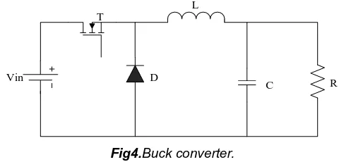
3.1. DC-DC STEP DOWN CONVERTER:
Step down converter is also referred to as a buck converter shown in Fig 4. For generating a lower voltage than the input, a step-down circuit[23]. The polarities in the input are the same. A switching regulator (break-down converter) is a DC-to-DC power converter that increases the voltage from its input (supply) to its output (load)[23, 24]. The switch turns on and, trying to charge it up, allows the flow of electricity to the output capacitor. Since the voltage across the capacitor cannot increase immediately, and since the inductor limits the charge current, the voltage across the capacitor during the switching process is not the power source's maximum voltage[25]. Now
the light is switched off. Since the current cannot quickly change in an inductor, the inductor produces a voltage across it. When the switch is powered off, this voltage is allowed to charge the capacitor and power the load through the diode, maintaining current output throughout the switching cycle[26].
D
C R
T
Vin
L
Fig4.Buck converter.
3.2. DC-DC STEP-UP (BOOST) CONVERTER
A step-up circuit used to produce a higher voltage than the input voltage[27]. The input polarities are the same. The ability of an inductor in boost converter is to endure current changes by generating and removing a magnetic field[28]. For a boost converter (Fig 5), the output voltage is usually higher than the input voltage [28-30]. When the switch opened, the current flows through the inductor in the clockwise direction and produces a magnetic field. The magnetic field on the left side of the inductor is positive. Because the impedance is higher, once the switch is released, the current will be decreased[31, 32]. The magnetic field previously made will be lost to hold the current to the load. It reverses the polarity (meaning the left side of the inductor is negative). As a result, two sources in series, creating a higher voltage, will charge the capacitor through the diode D.
v
Vin
L D
T C R
Fig 5. Boost converter.
3.3. DC-DC BUCK-BOOST CONVERTER
431
Vin
T
L D
C R
Fig 6. Buck-Boost converter.
3.4. DC-DC CUK CONVERTER
In a non-isolated cuk converter (Fig 7), there are two inductors, two capacitors, a switch (usually a transistor) and a diode. The figure displays the diagram. It is an inverter, so in terms of input voltage, the output voltage is the opposite. The capacitor C is used to transmit energyand connected alternately to the converter input and output by transistor and diode switching[38]. The two inductors L1 and L2 are used simultaneously to convert the origin of input voltage (Vi) and output voltage source (Co) into current sources. In a short time scale, an inductor can view as a current source that holds a constant current[39, 40]. This conversion is essential because if the capacitor were attached directly to the source of the voltage, the current would be limited only by the parasitic resistance, resulting in a high energy loss[41]. Charging a capacitor with a current source (the inductor) prevents the resistive current from being restricted and the resulting energy loss.
L2
L1
C1
Vin
T
D
C2
Vo
Fig 7. Cuk converter.
3.5. CHARGE PUMP
Charge pump converter (Fig 8) used to turn up or down the voltage in small-power applications[42]. Charge pumps have used some form of changing method to regulate a connection with the supply voltage through a load capacitor. In the first step, a capacitor is connected to the same voltage using a two-stage system. In the second stage, the circuit is modified to allow the capacitor to be in series with the supply and the load. It doubles the charge voltage— the number of the condenser's initial supply and voltages. The high frequency eliminates the capacitance required because, in a shorter phase, less charge must be stored and dumped[43].
Fig 8. PLL charge pump.
4. ISOLATED CONVERTERS
Isolated converters have a distinction between input and output terminals. These have the characteristics of isolation from high voltage. It is possible to block the noise and intrusion[44]. This makes it possible to make a cleaner DC source. They split into two groups, Flyback converters, and Forward converters.
4.1. DC-DC FLYBACK CONVERTERS
Flyback converter functions like the non-isolating class buck-boost converter[45]. The Flyback converter topology is shown in Fig 9. The difference is that a transformer used to store energy instead of an inductor. When the current stream cut through an inductor, the energy stored in the magnetic field is released by a sudden change in terminal voltage. If a diode is useful for carrying out the stored energy somewhere, the diode is called a fly back diode[15]. It requires only one inductor winding so that the inductor is called a flyback transformer. This device can only transfer energy when the main switch is off to the secondary side of the power supply. The simple flyback converter uses a relatively small number of components. A switching system cuts the DC voltage input and moves the power in the main through the switching circuit to the secondary. A secondary diode sets the voltage while the capacitor smoothes the balanced voltage. For a practical circuit, a feedback loop used to track the output voltage and while a computer switches the control loop. The fly-back converter is used for a broad range of digital devices such as TV sets, standard computer voltage regulators, mobile phone, personal device chargers, high-voltage TV and display CRTs, lasers, xenon flashlights, copiers, etc.
Vin
T
D
C R Vo
432
4.2. DC-DC FORWARD CONVERTER:
The forward transducer (Fig 10) is a DC / DC converter that uses a transformer to maintain increased voltage output (depending on the transformer ratio) and provide galvanic insulation to the load.Higher and lower voltage outputs can be delivered simultaneously to multiple output windings [7, 46, 47]. By contrast, the forward converter (based on a transformer with windings with the same polarization, higher magnetizing inductance, and no air gap) does not store energy during the conductive time of the switching element — unlike inductors, transformers cannot save a considerable amount of energy[43]. Instead, during the transfer process, energy is immediately transferred to the forward converter output via the transformer action.
Vin
T
D3
D2
D1 L
C R V0
Fig10. Forward converter.
Table1:Comparison of types of DC-DC converter.
Converter Type Switch (S)
In d u ct o r( L )
Ca pac itor( C)
Diode (D)
Voltage Equation
Duty
cycle Pros Cons Application
Non- Non- Isolated
Con
Boost convert er
1 1 Nil 1 Vi=(1-D)V0 D=1-(Vi/V0) High output voltage.
Large output capacitor is required.
Automotive applications.
Buck convert er
1 1 Nil 1 Vi=Vi-V0 D=V0/Vi
Efficient power conversion extends battery life.
Efficiency is poor for high gain.
Used as
interface between battery and
components in electronics appliances.
Buck-boost convert er
1 1 Nil 1 dIVi/L L/dt= D=VV 0/ 0-Vi
Efficiency of regulating the output voltage is high.
Complexity in circuit.
Used in the battery power systems, Adaptive control applications.
Cuk convert er
1 1 2 1 VC=V0/D V0/Vi= D/1-D
Continuous input and output current, efficient voltage regulation
High current stresses on the switch.
Switch mode power supply.
Isolated Converter
Flybac k convert er
1 1 2 2 V0=N2/N1 - VIN.1-D
V0=D/1-D
Voltage rating on secondary components is low.
More ripple current.
Cell phone and mobile device chargers.
Forwar d convert er
1 1 1 2 V0=NS/NP VS.D V0=D/1-D
Due to much larger
magnetizing inductance lower active device peak current.
Increased cost; transformer of the forward converter doesn’t stores energy. Double
input full bridge convert er
8 2 1 12 V0=N1/N2*V1 +N1/N2*V2
D=(3.14- 01)/6.28
Higher output voltage, higher output power and higher
Transformer Utilization Factor
More discrete components used.
Converting AC power to DC using a Bridge Rectifier.
Multipo
rt 6 0 7 0
V0=N1/N2*V1 +N1/N2* V2
V0=D/1-D
A minimal number of
Power flow management is
433
5. DIFFERENT INPUT ND OUTPUT CONFIGURATION:
The non-isolated converter is simple in structure and does not require any isolation[40, 48]. The non-isolated converters classified into various input and output configurations, Single-Input Single- Output (SISO), Single-Single-Input Multi-Output (SIMO), Multi-Input Single Output (MISO), Multi-Input Multi-Output (MIMO).
5.1. SINGLE INPUT MULTI OUTPUT (SIMO) CONVERTER:
Overall, different single-input dc-dc converters with varying gains of voltage merged to meet the requirements of varying voltage levels, making their system control more complicated and making the corresponding cost more expensive[12]. A single-input multi-output (SIMO) converter (Fig 11) to improve conversion efficiency and voltage gain, and to minimize voltage gain. It took more than three switches, however, for one output[49]. This system is only appropriate for the implementation of low voltage and power usage, and hard switching operation degenerates the power conversion [50, 51]. Suggested a new multi-output dc-dc boost converter that can share total output between different low- and high-power output voltage series. The proposed converter utilizes one power switch to execute the high-efficiency conversion targets, high step-up ratio and varying output voltage levels[52, 53]. In the proposed SIMO converter, the strategies of soft switching and voltage clamping developed to minimize the conduction and switching losses via the usage of a low-voltage-rated power switch[54]. The power switch to switch on the ZCS property and the leakage inductor effect may mitigate the loss caused by the reverse recovery current[24]. Nevertheless, in the conventional boost converter, the problems of stray inductance energy and reverse recovery currents inside diodes can also be solved so that high-efficiency power transfer achieved[55].
`
C1
D1
LT
C2
D4
Cpc
S1
Lp
D3
D2
La
Ca
Va
Coc
Voc
Vin
Fig 11.Single input multi output circuit.
5.2. MULTI INPUT SINGLE OUTPUT (MISO) CONVERTER:
Alternatively, MISO converters designed for parallel yields. Fig 12 represents the MISO converter. The most critical leeway of these systems is to have free power rates. Nevertheless, for remote control, they have to use such a large number of inductors and switches[44]. It is a significant disservice for related parallel MISO system. Therefore, structures of the MISO converter rendered using a single inductor, and subsequently, sources of voltage are worked on consecutively[56]. In this way, sometimes, control of these structures is given. A significant drawback to these systems is bidirect
ional convert er
conversion steps, low cost and compact
packaging.
complicated and slow.
management of the converter by a single digital
processor. Full
bridge boost convert er based distribu tion transfo rmer
8 2 2 8 V0=N*V1/
2*(1-D1) V0=D/1-D
The nominal powers of each transformer and rectifier are both reduced by four times.
Increasing number of the input ports, the magnetic integration.
Used in the Battery power systems.
Three input DC/DC boost convert er
4 2 1 4 V0=V1/(1-D1-D4) V0=D/1-D
Flexible
bidirectional load can be charged.
Several input sources with different voltage levels.
Smart homes, smart cities, and electric vehicles. ZVS
Multi input convert er
3 3 1 1 V0=1*V1/(1-D1)
D=[(1−D1)2+ (1−D2)2]
Pulse width modulation can greatly reduce the conduction loss of the switches.
Switching losses of the switches are effectively high.
Used in the applications of battery module.
Direct charge convert er
4 0 5 0 V0=2V2 *N*D1
434 the use of power sources that have a typical voltage standard.
Also, the control mechanisms are confused, and the use of a single MISO inductor converter increased enthusiastically. Three power layers limit the use of the MISO converters to acquire the high voltage gain, the generated voltage, and the power stream with two sources of information. By regulating the power flow of inductors connected with input sources, the generated voltage set to the reference[43, 57].Constant power flow from input sources cannot be given for this situation as they are employed successively. Luo converters specially used for high voltage gain, which expanded by using a converter layer for each info source. Unlike conventional Luo converters, the immateriality of Luo multi-input converters is more enthusiastic because they need multiple latent components that operate with high voltage rates. The use of dc/air conditioning inverters is another strategy to defeat the interoperability problem. In these systems, the inverter yields of each source of information associated with a first multi-winding transformer. In this way, the transformer connected to separate power sources[56]. Different inverters provide power control[19]. The transformer's voltage changed to dc, and then the entire output voltage is moved to dc transport. An extraordinary transformer's prerequisite, however, stands apart as a significant burden on these frameworks.
R1 L1
S1
R2
L2 S2
D1
D2
Rc
C1
Vo RLOAD
V1
V2
Fig 12. Multi input Single Output converter.
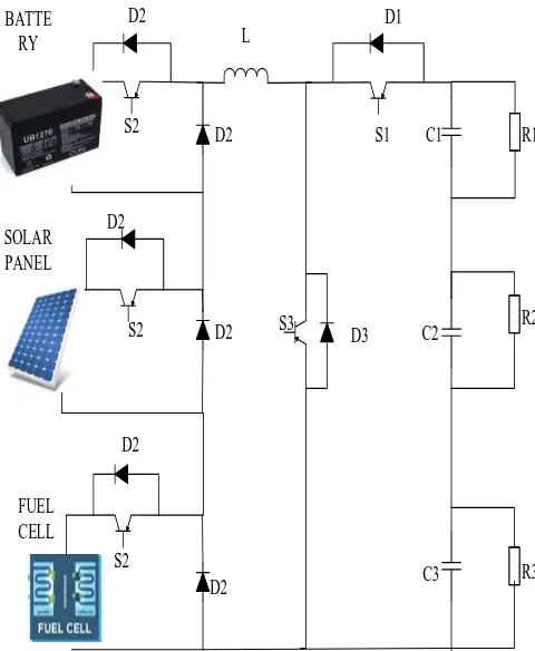
5.3. MULTI INPUT MULTI OUTPUT (MIMO) CONVERTER:
A MIMO converter has numerous DC contributions of various voltages and consolidates other MISO circuits to give the different levels[58, 59]. The sole reason for this kind of converter is to run the differentiated burdens .As in DC frameworks, there are such sorts of difficulties that require various voltages and flows to run, so by acquiring different yields from a single converter, and they can run effectively[60, 61]. The MIMO system mainly depends upon the MISO
technology. The design is pretty simple, and there is a need to select an output and find its duty cycle of a switch and distribute it accordingly[62, 63]. Fig 13 shows the circuit diagram of MIMO converter[62]. The higher the voltage, the lesser the duty cycle. All the design like it's a combination of three MISO converters from the same source .As of late, miniaturized scale networks with a mix of various vitality stockpiling units and sustainable power sources have changed the exploration enthusiasm because of the natural contemplations and unwavering quality prerequisite. In such conditions, Multi-Port Converters (MPC) assumes a crucial job in interfacing and incorporating these vitality sources to supply the heaps. Every subclass additionally isolated into MISO, SIMO, and MIMO. In the past barely any years, a great deal of research is done on MPCs. The majority of the specialists propose the MISO converter to join the diverse vitality sources at various voltage level[61, 64]. The issue in these converters is that just one source can supply capacity to the heap at a time. A portion of these examines show that their topologies have specific highlights like the MISO can spending plan the power between various vitality sources [65-68].
BATTE RY
SOLAR PANEL
S1
S3 S2
S2
S2
D1
D2
D2
D2
C1
C2
C3 D3
R1
R2
R3 L
D2
D2
D2
FUEL CELL
Fig 13. Circuit diagram of MIMO converter.
Table 2: Review on different DC-DC converters configurations
Year Title Author
Propos ed Convert er Used
No of Sourc es
Lo ad
No of I/P
N o o f O / P
No of D N o o f S
No of L
No
435 2009
A Multiple-Input DC–DC Converter Topology Alireza Khalig h, Multi-input buck boost convert er
2 R 4 1 3 3 1 1
Provides positive output voltage without any additional
transformer.
Large number of power switches, and a complicated gate drive circuit and a controller are needed.
A Systematic Approach to Synthesizing Multi-Input DC– DC Converters Yuan-Chuan Liu PWM convert er
2 R 2 2 2 2 2
PV array and the wind turbine, the proposed MICs can achieve higher converter
utilization.
Complexity lies in the principle of synthesizing MICs will be addressed and two families of MICs will eventually be synthesized.
2010
Multi-Output DC-DC Converters Based on Diode-clamped Converters Configuration: Topology and Control Strategy Alirez a Nami Multi output boost convert er
3 R 3 2 2 2 1 2
A simple and cost effective control strategy has been proposed to control the midpoint voltage.
As the number of output voltages increases, the number of required inductors will also be increased which leads to an increase in the cost.
Modelling and Control of Three-Port DC/DC Converter Interface for Satellite Applications Zhijun Qian Multi input buck boost convert er
2 R 2 1 3 3 1 3
The
communication delay and error can be avoided with the centralized control structure.
Full-bridge-based topologies utilize a lot of switches with complicated driving and control circuitry that counteracts the size benefit.
Topologies and control of a class of single inductor multiple-output converters operating in continuous conduction mode L. Benad ero Single inductor multi output dc-dc convert er
1 R 1 2 2 1 2
Each output unit has a dedicated channel controlled by a specific feedback loop, in which a linear combination of the error of the remaining outputs is used.
Limits of these parameters are, in fact, related with the range of power that this converter can manage.
2013
A High Step-Up Three-Port DC– DC Converter for Stand-Alone PV/Battery Power Systems Yen-Mo Chen three-port dc–dc convert er
3 R 3 2 5
2 coupl ed induct or 3
The coupled inductors are used to achieve high step-up voltage gain and to reduce the voltage stress of input side switches.
The leakage inductors of the coupled inductors will consume significant energy.
A ZVS Single-Inductor Multi-Input Multi-Output DC-DC Converter with the Step Up/Down Capability Hamid rezaK eyhani Single-Inductor Multi-Input Multi-Output DC-DC Convert er
3 R 3 3 6 6 1 2
The link capacitor is a considerably small ac capacitor with a high reliability and long life.
The proposed topology only needs to have a reverse blocking switch for each input or output of the converter.
Multivariable Control of Single-Inductor Dual-Output Buck Converters Jaya Deepti Dasik a SINGLE INDUC TOR multiple -output (SIMO) dc–dc convert ers
3 R 3 2 2 2 1 2
The proposed controller
minimizes the coupling between the outputs of the SIDO converter and provides satisfactory dynamic
performance in CCM operation.
Cross regulation is the main technical challenge of a single-inductor multiple-output (SIMO) dc–dc converter.
Integrated Dual-Output Converter Olive Ray, single-input– multiple -output (SIMO) dc–dc convert er
1 1 3 2 2 2 2
The use of a lower number of switches reduces the cost of the switch and its associated drivers.
For efficient operation of systems using multiple outputs, there should
be proper
436 converters for power flow management.
MultiinputDC–DC convertersinrene wable energy applications – An overview
Zubair Rehm an n,
Multiinp ut DC– DC convert ers
3 3 2 3 1 2
A lot of research and development has been carried out to enhance the reliability,efficiency, modularity and cost effectiveness
of these
converters.
In some cases a communication bus is also added for exchange of information between sources.
A
NonisolatedMultii nput Multioutput DC–DC Boost Converter for Electric Vehicle Applications Ali Nahav andi, multiinp ut multiout put dc– dc boost convert er
2 R 2 2 4 4 1 2
Transportation applications to provide
environmentally friendly operation with the usage of
clean and
renewable energy sources.
There are some well-known technical limitations to FCs: they have slow power transfer rate in transitory situations, and a high cost per watt.
Modelling and Controller Design
of a
SemiisolatedMult iinput Converter for a Hybrid PV/Wind Power Charger System
Cheng -Wei Chen
multiinp ut dc– dc convert er (MIC)
3 3 4 4 1 2
Simple circuit topology,
centralized control,
and
low-manufacturing cost and size.
Due to the cross-coupling nature of the MIC, the controller design is
not as
straightforward as the controller design in a single-input single-output system.
2016
A New Multiinput Three-Level DC/DC Converter Serka n Dusm ez Multiinp ut Three-Level DC/DC Convert er
2 R 2 4 4 3 3
MICs offer a cost-effective solution in applications which requires multiple input sources such as fuel cell vehicles and renewable energy systems.
For multiinput converters providing galvanic isolation, majority of the work has been devoted to phase-shifted full bridge converters. A Bidirectional
Nonisolated Multi-Input DC– DC Converter for Hybrid Energy Storage Systems in Electric Vehicles Furka nAkar Multiinp ut boost convert er
R 2 2 3 1 2
MICs are not only cost effective but also reliable, simple, and easy to control.
Does not offer flexibility in terms of the number of EES elements. Grid-Connected PV-Wind-Battery-Based Multi-Input Transformer-Coupled Bidirectional DC-DC Converter for Household Applications B. Mang u Multi-Input Transfor mer-Coupled Bidirecti onal DC-DC Convert er
3 3 2 4 2 4
Efficiently
integrating with energy storage elements.
These converters are not effectively utilized, due to the intermittent nature of the renewable sources.
Structure for input multi-output dc–dc boost converter Ebrahi m Babae i MIMO boost convert er
3 R 3 3 4 4 1 3
These converters have simple structure, central control, high degree of reliability and low building cost.
437 2017
A Novel Step-Up Multiinput DC– DC Converter for Hybrid Electric Vehicles Application Rouzb eh Reza Ahrabi Step-Up Multiinp ut DC– DC Convert er
3 R 3 4 4 2 2
The converter has the capability of providing the demanded power by load in absence of one or two resources.
Due to the fact that initial cost of PVs is high.
Adaptive Sliding-Mode With Hysteresis Control Strategy for Simple Multimode Hybrid Energy Storage System in Electric Vehicles Bin Wang Boost convert er
2 2 1 3 1 2
Absorbs all the braking energy such that the battery safety can be effectively ensured.
The major problem with the semi active HESS is that not all of the operating modes can be actively switched.
A Digital Method of Power-Sharing and Cross-Regulation Suppression for Single-Inductor Multiple-Input Multiple-Output DC–DC Converter Benfei Wang Single-Inductor Multiple -Input Multiple -Output DC–DC Convert er
2 R 2 2 5 4 1 2
The dynamic performance verification consists of load regulation, line regulation, response to output voltage reference step change, and response to input current reference step change.
The single-inductor SIMO dc–dc converters have the cross regulation problem in continuous
conduction mode.
Design and analysis of a novel SEPIC-based multi-input DC/DC converter Saeid ehKha demH aghig hian multi-input DC/DC convert er
2 R 2 3 3 2 2
MICs offer simple and more compact design and reduce the cost and complexity of the system.
In this converter, the loads power can be flexibly distributed between input sources.
Design of hybrid forward boost converter for renewable energy powered electric vehicle charging applications Peter K. Josep h hybrid forward boost convert er La m p loa d
4 2 2 4
For medium power EV charging applications, the DC–DC converter circuit should amplify the input voltage to a higher value
In the case of higher input variation, the charging efficiency is reducing rapidly in conventional topologies for ensuring the regulated output. Cost‐efficient non
isolated three‐port DC‐DC converter for EV/HEV applications with energy storage Kotha ndan Sures h Three port dc convert er
1 or 2 Dc loa d 1 or 2 1 o r 2
3 2 2 2
The presented converter has a compact structure with reduced component count and has the ability to supply the load power.
The major setback of this topology is that a fault in one part of the converter will affect the output of the whole converter system.
A New High Step-Up Multi-Input Multi-Output DC–DC Converter Parha m Mohs eni Multi-Input Multi-Output DC–DC Convert er
4 R 4 2 4 4 4 4
Maximum power point tracking (MPPT) is not available for each PV module and the reliability of the system is reduced.
The power flow of each input sources can be controlled by the duty cycle of each input stage power switch, and there is no limit for the duty cycle of power switches and number of input stages.
MISIMO: A Multi-Input Single-Inductor Multi-Output Energy Harvesting Platform Sally Safwa t Amin
A Multi-Input Single-Inductor Multi-Output buck
3 3 3 - 6 1 6
A power
management unit
(PMU) is
responsible for generating the various supply rails needed by these
438 in 28-nm FDSOI
for Powering Net-Zero-Energy Systems
boost convert er
functional modules.
A Multi Input Multi Output Bidirectional DC-DC Boost Converter with Backup Battery Port
Muha mmad Wase em
Multi Input Multi Output Bidirecti onal DC-DC Boost Convert er
3 R 5 5 1 2
The switching pattern of the proposed converter is interleaved, therefore, its input current has low ripple.
The main drawback of the dc-dc converters is the high input current ripples.
6. CONCLUSION
The objective of this paper is to review the wide variety of multi-input DC-DC converters in different aspects. These converters are used especially for providing continuous power supply to various applications like hybrid vehicles, DC microgrids, nano grids, battery charger etc. Among many converters as discussed in this paper, input and Multi-output converters have different features and widely used in many applications efficiently. In MIMO converter, single inductor and least number of switches have been used to increase efficiency and reduce size and cost. The multiple inputs are various renewable sources, so that energy consumption from non-renewable energy has been reduced. This converter boosts the input and pretends the battery to acts as input or output. The construction and advantages over other converters have been discussed in this paper. This type of multi-input DC-DC converter would be used for empirical research and commercial applications.
REFERENCES:
[1] Qian, Z., et al., Modeling and control of three-port DC/DC converter interface for satellite applications. IEEE Transactions on Power Electronics, 2009. 25(3): p. 637-649.
[2] Kuperman, A. and I. Aharon, Battery–ultracapacitor hybrids for pulsed current loads: A review. Renewable and Sustainable Energy Reviews, 2011. 15(2): p. 981-992. [3] Vilsan, M. and I. Nita. A hybrid wind-photovoltaic power
supply for a telecommunication system. in Proceedings of Power and Energy Systems in Converging Markets. 1997. IEEE.
[4] Sun, D., et al., Analysis and control of quasi-Z source inverter with battery for grid-connected PV system. International Journal of Electrical Power & Energy Systems, 2013. 46: p. 234-240.
[5] Suresh, K., et al., Cost‐efficient nonisolated three‐port DC‐DC converter for EV/HEV applications with energy storage. International Transactions on Electrical Energy Systems, 2019: p. e12088.
[6] Reddy, K.J. and S. Natarajan, Energy sources and multi-input DC-DC converters used in hybrid electric vehicle applications–a review. International Journal of Hydrogen Energy, 2018.
[7] Su, B., et al., A soft-switching post-regulator for multi-outputs dual forward DC/DC converter with tight output voltage regulation. IET Power Electronics, 2013. 6(6): p. 1069-1077.
[8] Khaligh, A., J. Cao, and Y.-J. Lee, A multiple-input DC– DC converter topology. IEEE Transactions on power electronics, 2009. 24(3): p. 862-868.
[9] Liu, Y.-C. and Y.-M. Chen, A systematic approach to synthesizing multi-input DC–DC converters. IEEE Transactions on Power Electronics, 2009. 24(1): p. 116-127.
[10]Qian, Z., O. Abdel-Rahman, and I. Batarseh, An integrated four-port DC/DC converter for renewable energy applications. IEEE Transactions on Power Electronics, 2010. 25(7): p. 1877-1887.
[11]Nami, A., et al., Multi-output DC–DC converters based on diode-clamped converters configuration: topology and control strategy. IET power electronics, 2010. 3(2): p. 197-208.
[12]Hang, L., et al., Asymmetrical secondary structure of LLC series resonant DC/DC converter for multi-output applications. IET power electronics, 2011. 4(9): p. 993-1001.
[13]Jiang, W. and B. Fahimi, Multiport power electronic interface—concept, modeling, and design. IEEE Transactions on Power Electronics, 2010. 26(7): p. 1890-1900.
[14]Wang, B., et al., Adaptive sliding-mode with hysteresis control strategy for simple multimode hybrid energy storage system in electric vehicles. IEEE Transactions on Industrial Electronics, 2016. 64(2): p. 1404-1414.
[15]Gunasekaran, D. and L. Umanand, Integrated magnetics based multi-port bidirectional DC–DC converter topology for discontinuous-mode operation. IET Power Electronics, 2012. 5(7): p. 935-944.
[16]Mangu, B., et al., Grid-connected PV-wind-battery-based multi-input transformer-coupled bidirectional DC-DC converter for household applications. IEEE journal of emerging and selected topics in power electronics, 2016. 4(3): p. 1086-1095.
[17]Stumberger, G., et al., Prevention of iron core saturation in multi-winding transformers for DC-DC converters. IEEE Transactions on Magnetics, 2010. 46(2): p. 582-585. [18]Cao, Y. and J.A.A. Qahouq, Evaluation of bi-directional
single-inductor multi-input battery system with state-of-charge balancing control. IET Power Electronics, 2018. 11(13): p. 2140-2150.
439 [20]Vel, C. and T. Venkatesan, Analysis of non-isolated
multi-port single ended primary inductor converter or standalone applications. Energies, 2018. 11(3): p. 539. [21]Nahavandi, A., et al., A nonisolated multiinput multioutput
DC–DC boost converter for electric vehicle applications. IEEE Transactions On Power Electronics, 2014. 30(4): p. 1818-1835.
[22]Akar, F., et al., A bidirectional nonisolated multi-input DC– DC converter for hybrid energy storage systems in electric vehicles. IEEE Transactions on Vehicular Technology, 2015. 65(10): p. 7944-7955.
[23]Michal, V., Optimal peak-efficiency control of the CMOS interleaved multi-phase step-down DC-DC Converter with segmented power stage. IET Power Electronics, 2016. 9(11): p. 2223-2228.
[24]Jabbari, M. and M.S. Dorcheh, Resonant Multi-input/Multi-output/Bidirectional ZCS Step-Down DC--DC Converter With Systematic Synthesis for Point-to-Point Power Routing. IEEE Transactions on Power Electronics, 2017. 33(7): p. 6024-6032.
[25]Yousefzadeh, V., E. Alarcón, and D. Maksimovic, Three-level buck converter for envelope tracking applications. IEEE Transactions on Power Electronics, 2006. 21(2): p. 549-552.
[26]Jiang, Y. and A. Fayed, A 1 A, dual-inductor 4-output buck converter with 20 MHz/100 MHz dual-frequency switching and integrated output filters in 65 nm CMOS. IEEE Journal of Solid-State Circuits, 2016. 51(10): p. 2485-2500.
[27]Faraji, R. and H. Farzanehfard, Soft-Switched Nonisolated High Step-Up Three-Port DC–DC Converter for Hybrid Energy Systems. IEEE Transactions on Power Electronics, 2018. 33(12): p. 10101-10111.
[28]Zhang, Z., et al., Dual-input isolated full-bridge boost dc– dc converter based on the distributed transformers. IET Power Electronics, 2012. 5(7): p. 1074-1083.
[29]Ahrabi, R.R., et al., A novel step-up multiinput DC–DC converter for hybrid electric vehicles application. IEEE Transactions on Power Electronics, 2016. 32(5): p. 3549-3561.
[30]KhademiAstaneh, P., et al., A bidirectional high step‐up multi‐input DC‐DC converter with soft switching. International Transactions on Electrical Energy Systems, 2019. 29(1): p. e2699.
[31]Chen, Y.-M., A.Q. Huang, and X. Yu, A high step-up three-port DC–DC converter for stand-alone PV/battery power systems. IEEE Transactions on Power Electronics, 2013. 28(11): p. 5049-5062.
[32]Danyali, S., S.H. Hosseini, and G.B. Gharehpetian, New extendable single-stage multi-input DC–DC/AC boost converter. IEEE Transactions on power electronics, 2013. 29(2): p. 775-788.
[33]Boora, A.A., F. Zare, and A. Ghosh, Multi-output buck– boost converter with enhanced dynamic response to load and input voltage changes. IET power electronics, 2011. 4(2): p. 194-208.
[34]Lu, Y., et al., A family of isolated buck-boost converters based on semiactive rectifiers for high-output voltage applications. IEEE Transactions on Power Electronics, 2015. 31(9): p. 6327-6340.
[35]Keyhani, H. and H.A. Toliyat. A ZVS single-inductor multi-input multi-output DC-DC converter with the step up/down
capability. in 2013 IEEE Energy Conversion Congress and Exposition. 2013. IEEE.
[36]Wu, H., J. Zhang, and Y. Xing, A family of multiport buck– boost converters based on DC-link-inductors (DLIs). IEEE Transactions on power electronics, 2014. 30(2): p. 735-746.
[37]Liu, L., et al., High‐gain boost dc‐dc converters: A‐LDC converter and S‐LDC converter. International Transactions on Electrical Energy Systems, 2017. 27(8): p. e2335.
[38]Safari, A. and S. Mekhilef, Simulation and hardware implementation of incremental conductance MPPT with direct control method using cuk converter. IEEE transactions on industrial electronics, 2010. 58(4): p. 1154-1161.
[39]Haghighian, S.K., et al., Design and analysis of a novel SEPIC-based multi-input DC/DC converter. IET Power Electronics, 2017. 10(12): p. 1393-1402.
[40]Behjati, H. and A. Davoudi, Single-stage multi-port DC– DC converter topology. IET Power Electronics, 2013. 6(2): p. 392-403.
[41]Kumaravel, S., et al. Dual-Input Dual-Output DC-DC Converter for DC Microgrid Applications. in 2018 IEEE International Conference on Power Electronics, Drives and Energy Systems (PEDES). 2018. IEEE.
[42]Akar, F., Y. Tavlasoglu, and B. Vural, Analysis and experimental verification of a multi-input converter for DC microgrid applications. IET Power Electronics, 2017. 11(6): p. 1009-1017.
[43]Dusmez, S., X. Li, and B. Akin, A new multiinput three-level DC/DC converter. IEEE Transactions on Power Electronics, 2015. 31(2): p. 1230-1240.
[44]Hwu, K. and W. Jiang, Time-sharing PWM control scheme for isolated multi-output DC–DC converter. Electronics Letters, 2015. 51(18): p. 1446-1447.
[45]Chen, C.-W., et al., Modeling and controller design of a semiisolated multiinput converter for a hybrid PV/wind power charger system. IEEE Transactions on Power Electronics, 2014. 30(9): p. 4843-4853.
[46]Joseph, P.K. and E. Devaraj, Design of hybrid forward boost converter for renewable energy powered electric vehicle charging applications. IET Power Electronics, 2019.
[47]Reddi, N.K., et al., An Isolated Multi-Input ZCS DC–DC Front-End-Converter Based Multilevel Inverter for the Integration of Renewable Energy Sources. IEEE Transactions on Industry Applications, 2017. 54(1): p. 494-504.
[48]Rehman, Z., I. Al-Bahadly, and S. Mukhopadhyay, Multiinput DC–DC converters in renewable energy applications–An overview. Renewable and Sustainable Energy Reviews, 2015. 41: p. 521-539.
[49]Dasika, J.D., et al., Multivariable control of single-inductor dual-output buck converters. IEEE Transactions on Power Electronics, 2013. 29(4): p. 2061-2070.
[50]Benadero, L., et al., Topologies and control of a class of single inductor multiple-output converters operating in continuous conduction mode. IET power electronics, 2011. 4(8): p. 927-935.
440 [52]Dhananjaya, M. and S. Pattnaik, Design and
implementation of a SIMO DC–DC converter. IET Power Electronics, 2019.
[53]Huang, M.-H., K.-H. Chen, and W.-H. Wei. Single-inductor dual-output DC-DC converters with high light-load efficiency and minimized cross-regulation for portable devices. in 2008 IEEE Symposium on VLSI Circuits. 2008. IEEE.
[54]Li, X.L., Z. Dong, and K.T. Chi. Analysis of Basic Structures of Interconnected Converters for Single-Input Multiple-Output Applications. in 2018 IEEE International Power Electronics and Application Conference and Exposition (PEAC). 2018. IEEE.
[55]Ray, O., et al., Integrated dual-output converter. IEEE Transactions on Industrial Electronics, 2014. 62(1): p. 371-382.
[56]Banaei, M.R., et al., Non-isolated multi-input–single-output DC/DC converter for photovoltaic power generation systems. IET Power Electronics, 2014. 7(11): p. 2806-2816.
[57]Amin, S.S. and P.P. Mercier, MISIMO: A multi-input single-inductor multi-output energy harvesting platform in 28-nm FDSOI for powering net-zero-energy systems. IEEE Journal of Solid-State Circuits, 2018. 53(12): p. 3407-3419.
[58]Gorji, J.G., K. Abbaszadeh, and F. Bagheroskouei. A New Two-input And Multi-output Interleaved DC_DC Boost Converter For Satellites Power system. in 2019 10th International Power Electronics, Drive Systems and Technologies Conference (PEDSTC). 2019. IEEE.
[59]Mohseni, P., et al., A New High Step-Up Input Multi-Output DC–DC Converter. IEEE Transactions on Industrial Electronics, 2018. 66(7): p. 5197-5208.
[60]García-Sánchez, J.R., et al., A robust differential flatness-based tracking control for the ―MIMO DC/DC Boost converter–inverter–DC motor‖ system: Experimental results. IEEE Access, 2019. 7: p. 84497-84505.
[61]Wang, B., et al., A digital method of power-sharing and cross-regulation suppression for single-inductor multiple-input multiple-output DC–DC converter. IEEE Transactions on Industrial Electronics, 2016. 64(4): p. 2836-2847.
[62]Babaei, E. and O. Abbasi, Structure for input multi-output dc–dc boost converter. IET Power Electronics, 2016. 9(1): p. 9-19.
[63]Shao, H., et al., A novel single-inductor input dual-output DC–DC converter with PWM control for solar energy harvesting system. IEEE Transactions on Very Large Scale Integration (VLSI) Systems, 2013. 22(8): p. 1693-1704.
[64]Gomathy, S., S. Saravanan, and S. Thangavel, Design and implementation of maximum power point tracking (MPPT) algorithm for a standalone PV system. International Journal of Scientific & Engineering Research, 2012. 3(3): p. 1-7.
[65]Yu, M.-H. and P.C.-P. Chao, A new mode multi-input–multi-output (MIMO) converter in an efficient low-voltage energy harvesting system for a gas sensor. Microsystem Technologies, 2018. 24(11): p. 4477-4492. [66]Esram, T. and P.L. Chapman, Comparison of photovoltaic