Fission Fragment characterization with FALSTAFF at NFS
D. Doré 1, F. Farget 2, F.-R. Lecolley 3, X. Ledoux 4, G. Lehaut 3, T. Materna 1, J. Pancin 2, S. Panebianco1 and the FALSTAFF and NFS Collaborations
1CEA, Centre de Saclay, Irfu/Service de Physique Nucléaire, 91191 Gif-sur-Yvette, France 2GANIL, CEA/DSM-CNRS/IN2P3, bd H. Becquerel, F-14076 Caen, France
3
LPC Caen, ENSICAEN, Université de Caen, CNRS-IN2P3, F-14050 Caen Cedex, France 4CEA/DAM/DIF, F-91297, Arpajon, France
Abstract. The Neutrons for Science (NFS) facility will be one of the first installations of the SPIRAL2 facility. NFS will be composed of a time-of-flight baseline and irradiation stations and will allow studying neutron-induced reactions for energies going from some hundreds of keV up to 40 MeV. Continuous and quasi-monoenergetic energy neutron beams will be available.
Taking advantage of this new installation, the development of an experimental setup for a full characterization of actinide fission fragments in this energy domain has been undertaken. To achieve this goal a new detection system called FALSTAFF (Four Arm cLover for the STudy of Actinide Fission Fragments) in under development.
In this paper, the characteristics of the NFS facility will be exposed and the motivations for the FALSTAFF experiment will be presented. The experimental setup will be described and the expected resolutions based on realistic GEANT4 simulations will be discussed.
1 Introduction
SPIRAL2 is an intense radioactive beam facility under construction at GANIL in Caen (France). The beams will be produced by fast neutron induced fission of 238U, the neutrons being generated by the breakup of deuterons on a carbon target. The high power superconducting LINear Accelerator of GANIL (LINAG) will deliver the needed high intensity deuteron beam. The construction was splitted in two phases. The accelerator, and two experimental facilities, the Super Spectrometer Separator (S3) and the Neutrons for Science (NFS) installation, are included in the first phase. For NFS [1], the LINAG will accelerate deuteron and proton beams to produce neutrons. Quasi-monoenergetic beams up to 31 MeV and white spectra up to 40 MeV will be obtained. An area of 30 meters long will allow time-of-flight measurements. In addition, activation measurements with neutrons, protons and deuterons will be possible. The NFS facility is described in section 1 of the present work. Studies for the optimisation of some components are also presented.
Thanks to this new neutron facility, fundamental physics and nuclear data measurements in an energy domain not yet exploited will therefore become possible. For example, fission fragment yields and neutron multiplicity data are of particular interest for the nuclear data community in view of the development of fast reactor technology and of reactors dedicated to the incineration of minor
C
Owned by the authors, published by EDP Sciences, 2013
actinides. Moreover, for the development of physics models, a lot of information is needed for a complete and precise description of the fission process. These arguments have motivated the development of a new detection system called FALSTAFF (Four Arm cLover for the STudy of Actinide Fission Fragments). Based on time-of-flight and residual energy technique, the setup will allow the simultaneous measurement of the complementary fragments charge, velocity and energy. The combined measurements of velocity and energy provide information on the mass of the fragments before and after the neutron evaporation. Neutron multiplicity as a function of the fragment mass may then be deduced directly from the difference between pre- and post-neutron masses. The experimental setup is presented in section 2 as well as the different phases of the project. Results of simulations are exposed and expected mass resolutions are discussed.
2 NFS facility
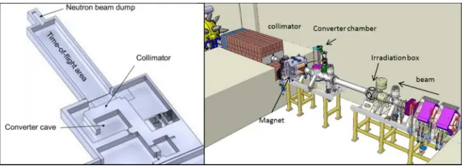
The two rooms of NFS, the converter cave and the time-of-flight area, are shown in the left part of Figure 1. The neutron collimator is embedded in a thick concrete wall between the two rooms. The neutron beam dump is placed at the end of the time-of-flight area. In the right part of Figure 1, the components of the converter cave are shown: the beam line, the irradiation box, the converter chamber, the magnet and the proton beam dump.
Fig. 1. Schematic view of the NFS facility (left panel) and its converter cave (right panel).
The production of mono-energetic neutron beams is based on the reaction 7Li(p,n)Be with a thin lithium target (1-3 mm). After crossing the converter, the protons are deflected toward a beam dump thanks to a bending magnet. For the production of white spectra, thick (8 mm) carbon or beryllium targets stop the deuteron beams. The choice of a rotating target has been made to sustain 2kW, the maximum power deposition allowed at NFS. The expected neutron energy spectra obtained with the two different modes are shown in Figure 2. The mean energy of the white spectrum (left part of Figure 2) is around 14 MeV. In the right part we observe that the monoenergetic peak is accompanied by a continuous tail produced by breakup processes.
The energy resolution achievable with a TOF technique at NFS will be around 1% (5%) for fast (slow) detectors thanks to the small time spread (<1ns) of the beam on the converter. Experimental setups can be placed between 5 and 25 m from the converter. The TOF hall can accommodate radioactive samples up to 1 and 10 GBq respectively for thick and thin targets.
The collimation of the neutron beam is obtained by using different materials arranged in rings. The inner part of the collimator consists in a set of iron cylinders with a conical channel to define the beam emittance. The outer part, made of concrete and borated polyethylene, absorbs the neutrons scattered in the iron cylinders. In Figure 3 a schematic view of the collimator (left) and the simulated spatial distribution of the neutron flux in the perpendicular direction with respect to the beam (right) are presented. At 2.5 cm from the beam line, the neutron flux is four orders of magnitude lower than in the beam. This very high signal over background ratio shows that the optimization of the collimator design is achieved.
Fig. 3. View of the collimator (left panel). Neutron flux distribution as a function of the distance from the beam line (right panel).
The neutron beam is “stopped” at the end of the TOF room in a beam dump whose design has been optimized in order to reduce the neutron backscattering to the TOF room and the gamma production. The LINAG and the NFS buildings are undergrounded at 9.5 meters. In 2011 the excavation for the whole SPIRAL2 phase 1 was completed. NFS construction will be achieved at the beginning of 2013. Next year will be devoted to the preparation of the building (electricity, fluids, lift, …). It is planned to equip NFS with the components presented in this paper during 2013 in order to be ready for the commissioning by mid-2014.
3 FALSTAFF experimental apparatus
Charge and mass distribution measurements in FALSTAFF are based on residual energy and velocity measurements. The 2V and EV methods [2] are used to determine the fragment mass before (initial mass Ai) and after (final mass Af) neutron evaporation. The 2V method based on mass
conservation (assuming that the average fragment velocity is not changed by the evaporation process) allows to determine the fragment mass before neutron evaporation from the two fragments velocity which is measured by their Time-of-Flight. The EV method permits to identify the mass after neutron evaporation from a coincidence measurement of energy and velocity. The necessary timing resolution, t, is obtained by using secondary electron detectors (SED), from which
t~100 ps may be expected. Fragment residual energies will be measured in a segmented ionisation chamber placed behind the stop detector with energy resolution of ~1%. In addition to the high precision requirement, the geometrical acceptance has to be large enough to perform experiments within a reasonable beam time. Taking into account the NFS neutron flux at 5 m from the converter, a geometrical acceptance of ~2% of 4π is needed to perform a measurement in ~10 days.
light fragments will be measured. In order to improve the position resolution in the stop detector, a magnet could be added to provide a better focalisation of secondary electrons. Results will be then compared to simulations to validate the setup. For the second phase, a second arm with a segmented ionisation chamber will be added. The second energy measurement is needed to identify the charge of the heavy fragment by charge conservation when it goes into the EV arm since its charge cannot be resolved using E-E correlation. In this configuration the setup could be installed at NFS to perform the first experiment with a 238U target in order to measure charge and final masses of light
and heavy fragments. Finally, the second arm will be completed with two SED detectors to provide the coincident time-of-flight measurements. The measurement of initial and final masses of both fragments will be then obtained and the associated neutron multiplicity will be determined. In addition, two other identical arms might probably be mandatory to reach the needed geometrical acceptance. The full setup will allow studying the fission final state as a function of the neutron energy with different actinide targets at NFS.
Fig.4. FALSTAFF schematic view for the first phase.
In direct kinematics the detection of low energy heavy ions is difficult since their energy loss is important while they cross layers. These losses have to be taken into account to obtain the correct velocity and energy. It implies that the ion positions on the different layers have to be known to calculate the crossed thickness and then apply the right correction. Simulations have been performed in order to evaluate the impact of the position resolution and the different layers on the mass and charge resolutions. A detailed geometry of the two arms, each one having the configuration presented in Figure 4 and including all the different materials has been carefully implemented in the GEANT4 Monte-Carlo code.
To determine initial and final masses, the analysis is based on an event-by-event iteration procedure which takes into account energy losses together with the expected experimental resolutions. Although the R&D on gaseous SED detectors [3] is still in progress, preliminary results from prototypes show that the time resolution is better than 150 ps and the position resolution is around 1.5-2 mm. For the ionization chamber, the energy resolution has not yet been measured, but a /E around 1% seems reachable.
To evaluate the mass resolution, one pair of 238U fission fragments has been simulated: 98Rb
(105 MeV) and 140Cs (74 MeV). They are emitted back-to-back in all the directions with an emission
Table 1. Simulated masses and resolutions taking into account different expected detection resolutions.
Simulated experimental
conditions (no evaporation)
Initial Mass Final Mass
Heavy Fragment
(amu)
Light Fragment
(amu)
Heavy Fragment
(amu)
Light Fragment
(amu)
without 140,0 ± 0,5 98,0 ± 0,5 140,00 ± 0,7 98,1 ± 0,3
A:E/E = 1% 140,0 ± 0,5 98,0 ± 0,5 140,00 ± 1,2 98,1 ± 0,9
B: Ax = 2, 1.5 mm 140,0 ± 0,5 98,0 ± 0,5 140,00 ± 1,6 98,1 ± 1,2
C: B+ t = 150 ps 140,0 ± 0,7 98,0 ± 0,7 140,00 ± 1,8 98,1 ± 1,6
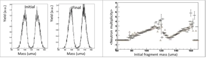
The next step is to simulate all pairs of fragment and to include the neutron evaporation. In the left part of Figure 5 the initial and final reconstructed mass distributions are shown. Next, the feasibility of extracting the neutron multiplicity as a function of the initial masses has been verified. In the analysis of the simulation data, the neutron multiplicity is determined event-by-event. Then, for a given initial mass, the average neutron multiplicity (<Ai – Af >) and the uncertainty (<Ai – Af >)/√N)
are calculated over N events. The result is presented in the right part of Figure 5. The grey triangles represent the simulated neutron multiplicity and the crosses the reconstructed one. One can clearly see that the extracted correlation is very satisfactory. The lack of statistics in the wings and the symmetric valley of the mass distribution lead to larger uncertainties and some gaps between simulated and reconstructed values. We observe also a steeper slope for reconstructed light fragments that has to be investigated.
Fig.5. Reconstructed initial and final mass distributions (left panel) and correlation between neutron multiplicity and initial masses (right panel).
4 Conclusions
The NFS facility designed for the production of intense pulsed neutron beams of energy going from some hundreds of keV up to 40 MeV is under construction at GANIL. The building construction is almost finished and the beginning of the commissioning is planned for mid-2014.
In parallel a new experimental setup dedicated to the characterization of actinide fission fragments is under development. In addition to the charge, mass and energy of both fragments in coincidence, the FALSTAFF setup will allow the neutron multiplicity determination associated to each fragment. Simulations show that the foreseen experimental setup is able to provide the required precision.
References
1. X. Ledoux et al., Proc. of the 11th International Conference on Application of Nuclear Interactions, AIP Conference Proceedings 1412, 55 (2011).