Methods Of Forming A Program Of Repair And
Construction Work In The Reconstruction Of
Utilities
Gavkhar Zokirova, Lobar Yusupova, Nilufar Zufarova, Furkat Safarov
Abstract: This article is devoted to the planning system for repair and construction work during the construction and reconstruction of utilities, namely, the improvement of the conceptual and methodological basis for the development and adoption of decisions in the management of repair and construction works of utilities in conditions of heavy traffic. A statistical analysis of the source data and the selection of significant factors determining the problem are carried out. The method of systematic inventory of the irrigation and drainage system, the heat and water supply system, the method of choosing the best way to lay underground utilities based on the consideration of alternatives to open and trenchless tunneling using the construction of the ―decision tree‖ based on the mathematical model, which, unlike the existing ones, provides the optimal method, is used laying underground utilities in the face of uncertainty, as well as taking into account the priority of the set of estimates cing criteria of various technological, economic and organizational performance. A comprehensive methodology has been developed for choosing the optimal method for laying underground utilities in urban areas, characterized by a multi-stage approach to solving the multi-criteria selection problem, taking into account significant geological, technological, economic and organizational factors in the presence of incomplete initial information.
Index Terms: ballasting, categories of roads, communication, diameter of the pipeline, freestanding, soil conditions, traffic. —————————— ——————————
1
INTRODUCTION
Depending on the intensity of traffic, categories of roads, the diameter of the pipeline, production methods, soil conditions, the pipelines are laid out using methods: open, hidden and closed. Depending on the location of the pipeline, the gasket is distinguished: aboveground, underground, underwater. Open pipe laying is carried out on existing or specially erected building structures (walls, supports, overpasses) or in passageways and semi-passageways and galleries), in a trench (underground) or along the ground (on the ground) as follows:
on freestanding foundations or supports;
with ballasting (installation of goods on the pipe or with anchoring of the pipe into the ground) - an anti-ascent measure;
on the ground, followed by backfilling of the pipe with imported or local soil.
Depending on the type of gasket and / or transition, the pipeline design can be: arched; hanging; beam.
The choice of the trenchless method of laying pipes depends on the diameter and length of the pipeline, physico-mechanical properties and hydrogeological conditions of the developed soils and the equipment used.
Table 1. Recommended methods for trenchless pipe laying.
Way
Pipeline
Best soil condition
s
Speed of penetratio n, m / h
The necessar
y indentatio
n force, t
Restriction on the use
of the method Diamete
r, mm Lengt
h, m
Puncture: using a mechanic
al jack
50-500 80
Sand and clay without
solid inclusion
s
306 15-245
In rocky and siliceous soils not applicable
Hydro Puncture
100-200 30-40
Sand and
sand 1,6-14 25-160
The method is possible in
the presence of
water sources and places
for the discharge
of pulp 400-500 20
Vibro
Puncture 500 60
Incohere nt sandy,
sandy loam and quicksan
d
3,5-8 0,5-0,8
In hard and rocky soils
not applicable
Soil
piercer 89-108 50-60 Clay 1,5-2 - Also
Pneumati
c puncher 300-400 40-50
Soft soils up to group III
30-40 (without expanders
)
0,8-2,5
In soils with high water saturation
is not applied
____________________________________
• Gavkhar Zokirova, Senior lecturer of department “Building technology and organization” at Tashkent Institute of Architecture and Civil Engineering, Tashkent, Uzbekistan. • Lobar Yusupova, Senior lecturer of department “Building
technology and organization” at Tashkent Institute of Architecture and Civil Engineering, Tashkent, Uzbekistan. • Nilufar Zufarova, Senior lecturer of department “Building
technology and organization” at Tashkent Institute of Architecture and Civil Engineering, Tashkent, Uzbekistan. • Furkat Safarov, Senior lecturer of department “Building
718 Forced
400-2000 70-80
In the soil of groups
I-III
0,2-1,5 450
In quick soil, the method is
not applicable.
In hard rocks, it can only be
used for forcing pipes of maximum diameter.
Horizontal drilling
325-1720 40-70
In sandy and clay soils
1,5-19 —
In the presence of groundwate
r, the method does not
apply.
The layout of underground pipelines is the same as that of aboveground pipelines with compensation sections. Underground pipelines lying on a solid foundation and covered with earth are distinguished according to design schemes depending on the presence or absence of transverse stiffness rings and the length of the pipeline. In the world, trenchless drilling technology is known as "No dig" ("do not dig") and is used in the vast majority of cases when working under highways, railways, water bodies, and various ground facilities. The attractiveness of this method lies in the fact that over 90% of the volume of work is carried out directly underground.
Trenchless piping provides the following benefits. • Minimization of harmful effects on the environment. • Almost complete absence of damage to surface areas. • High level of safety of construction work.
• Reduced laying time.
• High level of mechanization reduces staffing.
• Possibility of carrying out work at subzero temperatures.
Together, the trenchless laying of gas pipelines and other types of pipelines brings significant economic effect and is highly environmentally friendly. There are several technological methods used for trenchless laying of communications. The selection of one of them is carried out based on the characteristics of the terrain and soil, the length and diameter of the pipeline being created, the timing of the work, the level of funding and other criteria. The most commonly used methods are:
1. Remediation (pipe replacement). This operation is performed by puncture device. This technology is very popular and is designed for the manufacture of small diameter wells (up to 500 mm). A puncture between the start and finish pits is carried out using a hydraulic jack (jack system) pushing through a steel pipe with a specially shaped tip. The tip, upon reaching the end point, is removed, and a polymer pipeline is arranged in the metal casing. In addition to jacks, vibration-shock, hydraulic or pneumatic installations can be used, each of which has its own competitive advantages, which requires careful analysis before the final choice of a technical version.
2. Punching. Trenchless laying of sewers or other types
of pipelines by means of forcing is similar to a puncture device. In this case, the open end of the pipe is equipped with a knife device and pressed into the ground. Entered soil is removed from the pipe cavity manually or by mechanical means.
3. Horizontal directional drilling (HDD) is one of the simplest, most effective and economical methods performed by special drilling machines. Horizontal drilling technology can be used with great success in almost any inaccessible place.
For the Russian company Spetspodzemstroy trenchless pipe laying is the main specialization. The accumulated experience and advanced technical base allow them to implement the most complex projects, and in the shortest possible time, with impeccable quality and at a very reasonable price. The most cost-effective way to lay pipes is trenchless drilling. The possibility of applying this method does not depend on the density of development on the territory of the pipeline construction, and work can also be carried out in any type of soil.
Due to the fact that most of the work is carried out underground, this method has several advantages:
the road surface is not damaged (saving time and money on its restoration);
landscape is preserved (green spaces are not damaged);
there is no need for demolition / transfer of elements of improvement (most important when laying pipes in the courtyards of residential buildings);
laying can be carried out under existing networks, without breaking them;
It is much easier to coordinate work with municipal authorities;
laying can be carried out in any weather conditions and in any season.
When arranging transitions of tunnels, collectors and pipelines of significant diameters and large lengths, adit or shield methods of laying are used.
The main work at the site of laying the pipeline can be divided into two stages:
• At the first stage, preparatory work is carried out - the construction of pits, the preparation of the necessary equipment and its installation in the working and receiving pits.
• At the second stage, casings and parts of the working pipeline are laid, the soil is disassembled, all necessary additional work on the arrangement of the pipeline is carried out.
The laying of pipes in a closed way can be carried out absolutely in any geoclimatic conditions:
1. in soils saturated with groundwater;
2. under water bodies of various lengths and depths; 3. in marshland;
4. in hard rocks (using jackhammers); 5. in loose rocks (shield gasket).
laying underground utilities, safety precautions are mandatory. Construction safety is a set of tools and events that prevent the construction workers from exposure to hazardous production factors. Specially developed safety standards for construction envisage the adoption of measures to protect workers from occupational hazards, which implies the use of tools, machinery, equipment that guarantee the safety of production. The puncture method is one of the varieties of trenchless technology for laying pipelines or cable communications, which is an alternative to the previously most common trench method of arranging underground engineering networks. The specificity of the puncture technique allows you to use it for laying pipes of any diameter. Moreover, the optimal soils for arranging punctures are clay and well compacted loamy. They manage to create punctures with the maximum diameter of the well and at the greatest possible distance. In sandy and heavy soils, the efficiency of work is markedly reduced, up to the impossibility of performing a puncture. To select the number and type of pressing apparatuses, calculations are made to determine the necessary pressing force. It depends on: the diameter of the pipe; the length of the laid pipeline; type of soil; landscape features. Efforts for puncture are different and range from 150-2000 kN. After calculating the necessary pressure, we can determine the type of retaining wall in the dug pit and the number of jacks for the power plant. The necessary equipment for puncture is a push-pump pump. It represents the hydraulic jacks GD-170 (one or two paired) placed on a common frame with a force of up to 170 tf each. Jack rods have a large stroke amplitude - up to 1.15-1.3 m. The jack installation is placed at the bottom of the working pit - it will be punctured from it. Not far from the pit is a hydraulic pump with a pressure of up to 30 MPa, otherwise 300 kgf / cm2. The puncture process itself is a cyclic indentation - the jacks alternately switch to forward and reverse. The impact on the pipe is carried out through the headgear with clamping clamps, ramrods or interchangeable pressure fittings. Using nozzles with a length of 1 to 4 m, having completely pressed the pipe by the stroke length of the rod, it is returned to its initial position and a double length nozzle is placed in the formed opening. This process is repeated until the puncture of the first link in the pipeline is completed (usually 6 m). After that, the next link is attached to it and the operation is repeated. A ramrod is a pipe with side openings. The distance between these holes is determined by the stroke length of the jack rods. The ramrods are divided into two types: internal (moving inside the casing and have a smaller diameter than the pipe being laid) and external (covering the casing from the outside). In the process of pushing the first link, with the reverse stroke of the rods, the ramrod also simultaneously moves back. The rod is rearranged in the next hole and the steps are repeated until the link is completely pressed in. Having welded the next link of it, they are pressed using the same ramrod. Typically, pipes are punctured using jacks in clay and sandy soils that do not have solid inclusions.
• Installation of GPU-600. When laying pipes of diameter from 104 to 630 mm, the length of which is up to 80 m, on the soils of groups I-IV (without large solid inclusions), we use the GPU-600 installation. Its principle of operation is called "walking jacks." First, with 1.2 m hydraulic jacks (rod stroke length), workers push a movable pressure plate with a pipe, turning on the oil station. Having completed the working cycle with the
reverse stroke of the jacks, the released mobile cycle is pulled up behind the pipe being laid. These operations are repeated until the first link is introduced into the ground. Then the slide with jacks, movable emphasis and pressure plate take their initial position. After that, the next link of the pipeline is mounted and the process is repeated.
• Installation of Glavmosstroy. It is advisable to place pipes with a diameter of 209 to 426 mm in soils of groups I – IV (regardless of humidity) up to 45 m in length using the Glavmosstroy installation - it works on the same principle of ―walking jacks‖ as the GPU-600.
• Soil piercing and pneumatic punches of types IP-4605, PR-400 (or СО-134), PR-60 (or СО-144) and IP-4603 are used by us for laying pipes with a diameter of 63 to 400 mm using the closed method. Pneumatic punchers of the "Mole" type allow you to create wells of any kind (open / closed, inclined / horizontal) with sealed walls up to 40-50 m long. his working body, thus driving it into the ground.
• Hydro puncture. Using the kinetic energy of the water stream, we can pierce the pipes using a hydraulic piercing method. In this case, a jet of water emerging from a special nozzle on the front of the pipe blurs the hole up to 500 mm in diameter. Pipes are laid in it. Water consumption is calculated taking into account the pressure, speed of the stream and the type of soil. This method has its own characteristics: the work is simplified and the well formation rate is increased to 30 m / shift, but deviations from the design axis and the penetration length may not exceed 20-30 m. At the same time, the working conditions themselves become more complicated - the working pit becomes dirty.
Complex soil installations:
Laying pipes in quicksand, incoherent sandy and sandy soils, it is possible to speed up the process by vibration piercing. In the special installations of this method, the causative agents of oscillations directed longitudinally are used. Pipes up to 500 mm in diameter are laid with a vibro-puncture for a maximum length of 35 to 60 m, the penetration rate in this case is up to 20-60 m / h. In the same way, pipes can be removed from the ground. Focusing on greater efficiency, we most often use the UVVGP-400 installation designed by VNIIGS. The principle of operation is as follows: a casing with a tip on one side, the other side is placed in the shock part of the vibratory hammer. Submitting to shock impulses, supported by static indentation by the loading pulley, the pipe moves in the ground. To carry out the puncture, we can also use the UVG vibration-shock installation of the MINHiGP design named after Gubkin. It is suitable for laying by a method of vibro-shock punching a casing from 530 to 1020 mm in diameter, with a conventional puncture - for pipes 530 mm in diameter. Technological features of the puncture deviceFor the puncture device, several different methods can be used that require the use of appropriate equipment.
• Mechanical puncture, allowing to achieve the longest well length.
• Hydro-puncture, in which kinetic energy of a stream of water supplied under high pressure is involved. At a high penetration rate, its length is limited to 20–30 meters.
720 installations have been created. The maximum effect is
achieved with a combined effect on the soil, including shock, vibration and pressing loads.
• Puncture with screw soil piercers for the production of small diameter wells (up to 108 mm).
• Puncture with pneumatic punchers, which have high performance and allow not only to lay new pipelines, but also to extract pipes that make up the previously created pipelines.
• Each of these methods has its undoubted advantages, but also certain disadvantages. The choice of a specific technique is determined by the hydrogeological features of the terrain and soil characteristics, the parameters of the pipeline being created, and the technical capabilities of the contractor.
2
METHODS
OF
RESEARCH
The sequence and technical nuances of the puncture can vary based on the design features of the equipment used. One of the very popular ways to puncture under roads, railway embankments, etc. is the application of a controlled puncture installation. Its key element is a hydraulic jack, due to the force of which the pilot head is pressed in, followed by the introduction of a conical expander. Initially, the receiving and starting pit is created at the required points. In the starting at the calculated depth, a jack frame is mounted. The accuracy of its position is controlled with the help of geodetic tools, and the coordination of the driving direction is provided by the location system integrated into the pilot head. When laying water supply networks, gravity and pressure sewers, gas and oil pipelines, as well as tunnels and reinforced concrete collectors, the elements of which are closed along the perimeter of the form, trenchless laying is used by the forcing method.
The advantages of this method: • high speed of work;
• due to the absence of a trench, there is no danger of collapse of the soil;
• minimum costs for the placement and operation of special equipment;
• to carry out work, on average, only 3-4 workers are required;
• low deformation of the landscape.
The trenchless laying by the punching method is special in that the front end of the casing is equipped not with a conical nozzle, but with a knife, which does not prevent soil from entering the pipe. For jacking jackets, push-jack pumping units are used, which consist of 2, 4, 8 or more hydraulic jacks operating from high-pressure pumps. The required number of jacks is determined depending on the required pressure. Using this method, we can lay steel cases of large diameter. When punching the LDP (this is especially true for work in hard soils), it is necessary to use special-purpose pressure plants, consisting of several jacks, with an effort of more than 10 thousand kN, here it is also necessary to use strong stop walls.
• Initial (preparatory) stage. A working pit is being developed by a construction company and is engaged in its arrangement (pouring a stop wall for jacks), then we install the necessary equipment.
• The main stage. Directly indenting the pipe (casing) by means of jacks, which alternately switch from direct to reverse. The speed of penetration depends on the type
of installation.
• The final stage. The soil is being disassembled using one of the selected plants.
There are two types of punching: manual and mechanical excavation. However, based on many years of experience, it can be noted that manual excavation is not very effective (requires great effort and time), which is why most often when installing pipes by indentation, installations with mechanized excavation and removal of soil are used. Installation of hard currency Glavmosstroy. With its help, we lay pipelines up to 920 mm in diameter in soils of the I-III group. This installation allows you to lay pipes at a speed of 18 m per shift, due to the pressure of the hydraulic system - 300 kgf / cm2 (30 MPa) with a stroke of 1.15 m. The total mass of the installation is 13 tons. Installation includes:
• two hydraulic jacks GD-170/1150, having individual pumping stations of the N-403 series;
• three-drum winch (for removed soil);
• mechanisms for transmitting pressure forces to the pipe end;
• section of knives with a system of rollers; • pressure control valve with control equipment.
(VERMEER) are needed and are carried out, which allows for horizontal directional drilling to be carried out without involving third-party services.
This method has several significant advantages: • it is possible to lay pipes of almost any diameter; • minimized effort;
• work is being done underground and there is no need to block traffic;
• landscape integrity is maintained.
However, there is a serious drawback - the need to extract soil from the well. To eliminate this drawback, technologies are used that allow the excavation of horizontal workings without removing soil – drilling and rolling using specialized soil rolling equipment. Work on drilling wells and laying the pipeline are of two types: combined and separate. Separate involves preliminary drilling of a pioneer well and subsequent placement of pipes in it, after removing the drilling rig. Work with the combined method is carried out simultaneously - promoting the drilling tool and placing pipes. Various installations depending on the length of the laid pipeline and its diameter.
• A DM-1 type drilling and auger rig with a mechanical drive that creates wells up to 40 m long and up to 325 mm in diameter in clay soils.
• An eccentric-drilling installation of the Zaporozhye type with the principle of cyclic soil removal is suitable for laying large diameter pipes. This installation is equipped with a set of equipment selected for the corresponding pipe diameter - 820-1420, 426-630 or 325-377 mm, which in the process of work are sequentially increased by 6 m (link length) with a penetration rate of about 6-12 m per shift.
• GB or UGB. The most commonly used and more productive are unified auger horizontal drilling rigs. With the help of these installations, a combined process of laying and drilling is carried out, soil from the well is removed continuously (scheme in Fig. 21.6 a). They are intended for laying a pipeline 40-60 m long and 325-1420 mm in diameter for soils up to group IV. The drilling speed in this case is from 1.5-1.8 and up to 12.7-19 m per hour. Briefly describe the operation of GB and UGB installations as follows. In the process of laying the pipe, the milling head performs mechanical drilling, a screw conveyor extracts loosened soil from the well.
• The PM-800-1400 machine is used for laying pipes with a diameter of 830 to 1420 mm in any soil, except for rock and quicksand. The installation has a mass of 11.2 tons, engine power 24.6 kW. At a speed of 15 m per shift, pipes are laid to a length of 120 m. When laying the pipe, the soil is removed with a scoop, which is removed from the pipe with a special device. From the scoop, the soil is unloaded either into the tank or into the pit.
• Installing GB-1621. With its help, work is carried out by the method of punching or horizontal drilling, in which the development and subsequent transportation of soil from the bottom are mechanized. Laying length up to 60 m at a speed of 10-12 m per shift.
Pioneer well drilling
It is also possible to carry out horizontal laying of horizontal drilling by the method of expansion of a pioneer well. Using a
GB or UGB installation, a pioneer well is being developed and at the same time a leader pipe is laid in it. During the reverse stroke, an expander installed at the end of the screw increases the pioneer well for the diameter of the large diameter pipe. The leader pipe is removed from the well by the laid pipeline. But more often, for effective work when laying pipes with advance horizontal preparation wells are used pneumatic punch. With their help, wells 40-50 m long with compacted walls and diameters from 63 to 400 mm are arranged. A pneumatic punch is introduced into the ground from the inlet pit towards the receiving pit. With the help of a conical front end, the soil is compacted and parted to the sides, thereby forming a well. Laying steel pipes, the pneumatic punch performs the role of a shock assembly, which is attached to the rear end of the pipe and clogs it into the ground. The main aspect when laying pipes is to ensure and verify compliance with the position specified by the project during the laying process. To ensure the desired direction, horizontal and vertical guide frames are required, which are installed in the working pit. When using a pneumatic punch, it is possible to replace old pipelines with new ones having the same diameter or more. In this case, the new pipe is welded to the old (which is subject to replacement) and is cut off as it exits. Using a pneumatic punch, steel pipes up to 800 mm in diameter can be removed, in which case the pneumatic punch serves as a percussion mechanism mounted on the front end of the pipeline. Extensive experience in the application of HDD-drilling technologies allows us to draw conclusions about its significant advantages over other pipeline laying methods. Unlike the labor-intensive trenching of pipelines, drilling using the HDD method is a fairly simple operation.
Stages of the work:
1. Drilling a test well using a beveled drill head, equipped with a drill blade and a probe emitter that controls the angle, depth and direction of drilling. 2. Extension of the well to a size slightly larger than
the diameter of the pipe being laid.
3. Laying the pipe into the pipeline using a trimmer and drill thread.
Such a scheme makes it possible to create wells of various trajectories and bypass underground obstacles. In addition, this method allows you to lay pipelines of any diameter, and also reduces the timing of work and reduces financial and labor costs for their implementation.
• elimination of the possibility of erosion of the banks and bottom when performing work under water bodies;
• high safety of construction works and minimizing the risk of emergency situations;
• preservation of the natural landscape; • the ability to avoid open excavation;
• mobility and compactness of the complexes performing HDD-drilling.
722 800 mm in diameter from the soil. The length of the pipes to be
removed will depend on the adhesion of the soil and the surface of the pipe. You can replace pipes with new ones with a large diameter. When constructing tunnels intended for various underground utilities (including heating networks, cables, gas pipelines) at great depths, a shield tunnel method is used.
The features of this method allow:
• tunneling in any hydrogeological conditions; • increase the maximum possible laying depth; • greatly facilitate the choice of communications route; • simultaneously lay several pressure pipelines for
various purposes.
The shield gasket for the installation of tunnels and collectors is the development of soil under cover of the shield, as well as the fixing of the tunnel or collector with reinforced concrete, cast-iron tubing of the prefabricated type, or with monolithic blocks and ceramic blocks. When paneling is used, a tunneling shield is used, which is made in the form of a metal shell, which in diameter is equal to the outer diameter of the tunnel being arranged.
The driving shield has three main parts:
• the first (front) is wedge-shaped, it happens with a visor and without, performs cutting functions;
• the second (middle) includes jacks and is a support; • the third (back) is the tail.
The formation of the lining (otherwise-walls) of the collector is carried out in the rear of the shield. For work, shields of various types are used, having a diameter of 2 to 5 m. Shields are non-mechanized, partially mechanized and mechanized, depending on the methods of development and transportation of soil. Non-mechanized shields are easy to operate and are applicable for the installation of collectors up to 2.5 m in diameter, and mechanized shields, in turn, are more productive, but also more difficult to manage.
• Non-mechanized shields differ little in design, the head part, which can be closed and open, as well as horizontal shelves and rigid lattices, can be distinguished from the differences. If the head part is open type, then the cutting part is provided with a visor with a wedge-shaped knife. The shield moves forward due to hydraulic jacks, which are installed around the perimeter of the shield, their rods abut against the previously laid parts of the tunnel lining. The supporting part located in the middle of the shield guarantees its rigidity and strength. Under the protection of the tail (rear) part, 1-2 rings of the precast lining or monolithic section are mounted. Depending on the type of soil, the diameter of the excavation, the number of jacks and the power of the pump unit, the penetration rate by non-mechanized shields is 0.8-1.2 m per shift.
• Mechanized shields provide mechanisms to develop and guide the ground for loading. The working part of such shields can be rotary, excavator, rod or hydromechanical. The most commonly used shields with excavator and rotary working bodies. In shields with a rotary working part, the soil developed by the cutters constantly falls onto spiral blades and is sent to a conveyor belt, which transfers it to carts with a
removable body. Regardless of the movement of the shield, hydraulic jacks advance the working body by 1 m, and at the same time the conveyor moves.
Work on the penetration of panels is carried out in three stages.
1. The preparatory phase. Here, workers create an initial or assembly shaft, along which a shield will be lowered, arrange ventilation, supply electricity, etc. Create conditions for haulage of the soil - pave the way, equip the construction site and the mine yard with everything necessary. An emphasis is made of piles in the mine and the shield is installed in the position indicated in the design.
2. The main stage is the direct movement of the shield and the installation of the lining.
3. The third stage is necessary for tunnels under the sewer collector - a tray is arranged in it.
Directly driving the collector consists of several processes: starting from disassembling the soil, moving the shield, supplying materials, lining devices and completing auxiliary work involving the laying of communications and the construction of the rollback routes. The main process is considered to be the development of the breed, since the penetration rate depends on it. Labor costs depend more on the type of shield - non-mechanized shields with manual disassembly of the rock significantly increase the complexity. That is why, if the type of soil allows, we use mechanized shield systems. Various hydrogeological conditions can create some difficulties during work, but modern equipment and developed laying methods allow working in almost any type of soil.
• In hard rocks. In soils where it is not possible to use mechanized complexes (for example, in hard soils), our workers use non-mechanized shields and manually develop the soil. When laying tunnels in hard rocks, they either use jackhammers or use the explosive method.
• In flooded soils. Significantly complicated the performance of work in weak and saturated soils. In this case, we use the method of artificial drainage of the bottom in the wells with ejector or light needle filters, or submersible pumps. With a low coefficient of soil filtration, we are developing when freezing the soil or using the caisson method (protection of compressed air).
courtyards). With the open laying of pipelines, bridge bridges are built through the working trench, so the movement of people and vehicles is practically not hindered.
Carrying out trench laying of pipes, special installation conditions are observed:
1. The pipeline is placed in a trench 20 cm below the level of soil freezing.
2. The pipe is installed at a depth of not less than a meter (calculation from the upper wall of the pipe). This guarantees protection against damage under temporary load.
3. When connecting pipes directly to the trench - at the junction we expand the trench (to install the necessary equipment).
4. Before laying pipes, the bottom of the trench is leveled.
5. When working in hard soils, a layer of soft soil is placed under the base of the pipe.
After checking the structure of existing communications and eliminating the possibility of damage, we use trench excavators. In this case, the execution time is significantly reduced: there is simultaneous work on cutting, excavating and cleaning the soil. If the communication density is high, then shovels are used. After trench digging, pipe-laying cranes are used to place the pipe in the trench. In the case when insulation and laying work are carried out separately, the pipes are lowered by taps equipped with soft towels. Having placed the pipeline at the design positions, we fix it. Lining mats (or protective wraps) are placed between the weighting reinforced concrete cargoes (or anchor devices) and the pipeline. The design of the mats is determined by the project. At the final stage, the trench is buried and restoration work is ongoing to cover the land.
Open pipe installation has several advantages:
• deviations from the planned position of the pipes are excluded;
• installation from a coil is easy and requires less effort; • Laying a long pipeline is faster.
The main disadvantage of the trench laying is the dependence of the possibility of applying the method on territorial conditions. Due to the fact that in areas where laying pipes in an open way is not possible, a closed (trenchless) method is used. When laying engineering systems for various purposes, there is an acute problem of their protection from the adverse effects of the environment. Often groundwater, various fungi and parasites corrode the surface of the pipes, which leads to their corrosion and destruction, and therefore increases the risk of accidents that pose a danger to humans and nature. For this reason, to prevent the harmful effects of biochemical factors on piping systems, modern scientists and engineers have developed a new method of protection - punching steel cases. Also, this method is called "soil puncture."
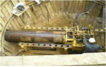
Fig 1. Pipe laying by manual punching.
The punching method has established itself as a reliable method for trenchless laying of pipelines, reinforced concrete collectors, tunnels and cases, the constituent parts of which are a perimeter closed structure. It is most optimal when it is necessary to lay pipes D 400–2000 mm in the soil of groups I-IV at a distance of up to 100 meters. The extrusion of steel cases D 160–2000 mm with a laying length of up to 70 m is used when it is necessary to lay the pipeline under railways, roads and other obstacles.
Fig 2. Punching Method.
The punching method consists in the fact that the pipe being laid, equipped with a knife, is pressed into the soil with the open part, while the soil falling into the pipe is manually developed or removed. CJSC IC ―Spetspodzemstroy‖ carries out ―soil puncture‖ using double hydraulic jacks with an indentation force of 200–400 tons. When using cases with a diameter of 1200–1400 mm, the total length of penetration is 50 m and the speed is about 10–12 m / shift.
• Low cost. When performing work, there is no need for expensive equipment.
• Laying is carried out using human resources, which allows you to control and, if necessary, change the direction of movement. This is especially important if you encounter unexpected obstacles in the puncture path that were not considered in the design.
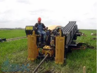
724 Fig 3. Trenchless cabling.
The air-laying method is now being used less and less, since lower initial costs result in numerous additional complications and financial losses during subsequent operation. At the same time, the use of traditional trench technology for arranging cable networks also poses a lot of problems for builders and others: the topsoil is destroyed, obstacles for cars and pedestrian traffic are created, the aesthetics of the surrounding space are violated, etc. In addition, in a number of places, laying open trenches is simply impossible - this is impeded by dense buildings, the presence of a highway, railroad tracks, and water barriers.
Trenchless Technology: A Progressive Solution
In the 70s of the last century in Russia for the first time a mechanized trenchless method of laying cable systems was applied. The complex mechanization of the process was achieved using special units - knife-type cable layers. The simplest machines are equipped with passive-type knives, while more modern ones have active (vibration) knives. Trenchless laying of power cables and other types of cable lines by applying the most advanced methods - horizontally directed drilling or soil puncture. The main competitive advantages of these technologies include:
• high environmental friendliness - no damage to the environment;
• performance of work without destroying the roadway and stopping traffic;
• the possibility of arranging a cable network under any kind of natural and artificial obstacles;
• reduction of time costs (in comparison with the traditional method) by 6–7 times and increase in labor productivity by almost 10 times;
• low cost.
Laying of PND110 cases for fiber optic communication is carried out in bundles of 4 pipes. Polyethylene pipes PND160, PND225 are laid for water supply networks. Since the puncture is controllable, work is also underway on laying sections of the gravity drain PND225 and PND315. The Eclipse location system allows you to withstand a given slope of 0.003.
Fig 4. Route and methods of laying heating networks.
Heat networks are divided into trunk, distribution, quarterly and branches from trunk and distribution heating networks to individual buildings and structures (SNiP 41-02-2003 "Heat networks").In settlements for heating networks, as a rule, underground laying is provided (channel-free, in channels or in city and intra-quarter tunnels together with other engineering networks). When substantiating, the elevated laying of heating networks is allowed, except for the territories of children's and medical institutions. Laying of heating networks in the territory that is not to be built outside of settlements should be provided for above-ground on low supports. Laying heating networks along embankments of public roads of categories I, II and III is not allowed. The laying of heating networks at a working pressure of steam above 2.2 MPa and a temperature above 350 ° C in tunnels together with other engineering networks is not allowed. Underground laying of heating networks is allowed to be provided in conjunction with the following engineering networks: in channels - with water supply systems, compressed air pipelines up to 1.6 MPa pressure, fuel oil pipelines, control cables intended for servicing heating networks; in tunnels - with water pipes with a diameter of up to 500 mm, communication cables, power cables with voltage up to 10 kV, compressed air pipelines up to 1.6 MPa pressure, pressure sewer pipelines. The laying of pipelines of heating networks in channels and tunnels with other engineering networks, other than those indicated, is not allowed. The intersection of heat networks of rivers, roads, tram tracks, as well as buildings and structures should, as a rule, be provided at right angles. When substantiating, intersection is allowed at a smaller angle, but not less than 45 °, and subway structures, railways - not less than 60 °.The intersection of the tram tracks by underground heating networks should be provided at a distance from the arrows and crosses of at least 3 m (in the light). When underground crossing thermal networks of railways, the smallest horizontal distances in the light should be taken, m:
1. to the arrows and crosses of the railway track and the places where the suction cables are connected to the rails of the electrified railways - 10;
2. to the arrows and crosses of the railway track with subsidence soils - 20;
3. to bridges, pipes, tunnels and other artificial structures - 30.
4. Crossing by heating networks of metro station structures is not allowed.
networks in the form of land plots with a width determined by the angle of repose of the soil, but not less than 3 meters in each direction, counting from the edge of building structures of heating networks or from the outer surface of an insulated heat pipe without channel laying (Order of the Ministry of Architecture , construction and housing and communal services of the Russian Federation of August 17, 1992 No. 197 ―On standard rules for the protection of communal heating networks‖) The horizontal and vertical distances from the outer edge of the building structures of canals and tunnels or the insulation shell of pipelines for channel-free laying of heating networks to buildings, structures and engineering networks should be taken in accordance with Appendix 1 of SNiP 41-02-2003 ―Heating Networks‖ (table 4.16, Appendix 6).
3 RESULTS
In engineering and geological surveys, design and construction of the foundations and foundations of underground utilities using previously unused (insufficiently tested) construction technologies, design solutions or design methods, as well as underground utilities of the 3 (complex) geotechnical category, it is necessary to provide scientific and technical support involving specialized geotechnical organization. The scope of work on scientific and technical support should be determined by the general designer and agreed upon by the construction customer. The structure of the scientific and technical support should include:
- development of recommendations for the program of engineering and geological surveys;
- assessment and analysis of engineering survey materials; - development of non-standard methods of calculation and
analysis;
- assessment of geological risks;
- forecasting the state of the foundations and foundations of the designed underground utilities, taking into account all possible types of impacts;
- assessment (geotechnical forecast) of the impact of construction on the surrounding buildings, the geological environment and the ecological situation;
- development of a geotechnical and environmental monitoring program;
- identification of possible emergency scenarios;
- development of technological regulations for special types of work;
- performance of research work;
- generalization and analysis of the results of all types of geotechnical monitoring, their comparison with the forecast results;
- prompt development of recommendations or adjustment of design decisions based on geotechnical monitoring data in case of deviations from the forecast results.
The program and results of engineering surveys, design documentation for the foundations, foundations and structures of newly constructed (reconstructed) underground utilities (including fencing of trenches and foundation ditches), as well as the results of an assessment of the impact of construction, protective measures projects and a geotechnical monitoring program, must undergo a geotechnical examination for the following underground communications:
- with a depth of more than 5 m;
- in the zone of influence of the construction of which existing buildings, structures and underground utilities are located;
- located in areas with the possible development of hazardous engineering and geological processes.
726 perform this type of work, the company uses the MNB-125
installation. The destruction is carried out using a metal conical expander, the diameter of which exceeds the diameter of the old pipe. The essence of the pipeline restoration methodology in general is as follows. At the start and end point of the section of the route to be restored, two pits are arranged. In the first (working) installation, the end is mounted to the second (receiving) end of the whip of a new pipeline or a new pipe is supplied in the case when the pipes are joined directly in the pit. From the working pit to the receiving unit, the installation pushes the rod string through the old pipeline, to which, upon exiting by means of a special connection, an expander is connected to the new pipe. When the rod string is retightened by the installation, the old pipeline is destroyed while the new pipes are pulled.
This method has significant proven in practice advantages:
1. high productivity of work (an interval of 100-200 m is usually performed per shift);
2. lack of dynamic impact on existing communications and the foundations of buildings;
3. there is no need for numerous additional approvals, as the route of the old pipeline is used;
4. the possibility of laying a new pipe of larger diameter.
4
CONCLUSION
1. Based on the previous sections, the laying of underground utilities can be carried out in closed or open ways. The choice of laying method and technology is carried out on the basis of a technical and economic comparison of options, taking into account:
the requirements of the applicable norms and rules for the design and construction of the corresponding type of underground utilities;
the size and length of the underground communications route;
engineering-geological, hydrogeological and town-planning conditions of construction;
ensuring the reliability of existing buildings, structures and underground utilities located in the zone of influence of construction;
terrain.
The laying of underground utilities in a closed way should be performed using:
- tunneling mechanized complexes (TPMK), - microtunnel tunnel complexes (MTPK), - horizontal directional drilling rigs (HDD) - puncture,
- punching.
Note: with the appropriate feasibility study, it is allowed to use other methods of laying underground utilities in a closed way. 2. The laying of underground utilities in an open way should be
carried out in trenches and partially in pits arranged with slopes or with the use of enclosing and retaining structures with a shallow depth of laying of utilities.
3. The following should be used as fencing trenches and pits when laying underground utilities in an open way:
fences from hotel elements (metal pipes, I-beams, piles, etc.);
sheet piling;
fences of the ―wall in soil‖ type, arranged by a trench method, from bisected or tangent piles;
fences, arranged using inkjet or other technology of soil consolidation;
wooden shields; fencing combined type.
5. A comparison of the two methods and methods revealed that, with urban development, the optimal laying method must be determined taking into account the advantages and disadvantages of the methods and methods. Given the urgent need to develop the optimal solution from many possible options, a search was made for methods to improve the technological preparation of the construction or reconstruction of utilities in conditions of heavy traffic. As a result, it is proposed to use the methods of statistical analysis by constructing decision trees based on a fuzzy programming apparatus, the theoretical foundations and practical application of which are discussed below.
5
ACKNOWLEDGMENT
The authors wish to thank A, B, C. This work was supported in part by a grant from XYZ.
6
REFERENCES
[1] N. N. Abramov Water supply. M .: Stroyizdat, 1982. [2] Sh.D. Askarov, L.A. Adilova, Kh. K. Tursunov and
others. The concept of development of urban development in Uzbekistan in the context of the formation of new socio-economic relations. TASI, Tashkent -2008, 304s.
[3] V.A. Afanasyev Stream organization of construction. L., SI, 1998 .-- 303 s.
[4] S.S. Bachurina Megapolis: methods and models for managing the processes of complex reconstruction of the existing buildings. M.: Sinteg, 2004. (Series "Project Management").
[5] I.S. Bondarenko, I.V. Barannikova Analysis of factors affecting the choice of communication tunnel construction technology. Mountain Information and Analytical Bulletin. Issue No. 10: Informatization and Management-1, 2008 - p. 124-129
[6] B. F. Beletsky Technology for laying pipelines and collectors for various purposes. M .: Stroyizdat, 1992. [7] N. Bozorboev, E. Makhamataliev, M. Turdialiev
―Kurilishnee tashkil etish wa rezhalashtirish‖, TAҚI, Toshkent, 2011.
[8] L.E. Wand Assessment of design decisions and its role in the optimization process in conditions of incomplete information. - M .: 1970.
[9] V.V. Vlasov, L.V. Kievsky, S.A. Shupikov Engineering preparation for construction: the experience of Ulyanovsk.-M.: Stroyizdat, 1989.
[10] I.G. Galkin Organization, planning and management of construction production. M., V.sh. 1997.
[11] General schemes of engineering support of Moscow for the period until 2020. scientific and technical report of the State Unitary Enterprise NIIPI of Moscow. 2002.
Stroyizdat, 1990.
[13] A.S. Gritsenko, Mutalova B.I. Planning, development and reconstruction of cities / study guide-Tashkent-2010, 156s.
[14] A.A. Gusakov, Ilyin N.I. Methods for improving the organizational and technological preparation of construction production. M .: Stroyizdat, 1985.
[15] L.G. Diekman Organization, planning and management of construction production. M., V.shk 1989.
[16] L.G. Diekman Organization of Civil Engineering. Reference builder. 2nd ed. M., SI, 1990 - 495s. [17] V. Dmitriev A. B. Ketaov City engineering networks. M