Modelling And Comparative FEA Of Conventional
Metallic & Composite Structure Of Slat With
Optimization Of Ribs
Damini Patil, Dr. Surbhi RazdanAbstract: An aerodynamic surfaces which are on the leading facet of the wings of the aircraft with fixed wings are known as Slat. When they are deployed the wings operate at greater angle of attack. This research paper introduces a modified design of slat section 1 which is modelled using modelling software CATIA. The proposed design will allow fitting an antenna made up of Kevlar which is a composite material. Kevlar is ten times stronger than stainless steel, raio-transparent and is bullet proof, these properties are essential for fighter aircrafts. The meshing is done using meshing software HyperMesh as it provides better tools for meshing. FEM Analysis of slats is done with help of designing and analysis software Patran.. Analysis results of modified structure are contrasted with the results of earlier metallic slats structure. Results obtained shows that it is preferable to replace aluminium metal by Kevlar Composite. It is an important factor to reduce weight in aerospace sector. Ribs of modified structure are optimized in this paper by removing material in different cut section such as trapezoidal, circular and triangular. Results of all three ribs with different cut sections are compared. It is observed that Ribs with circular cut section generate lower stress. Hence ribs with circular cut section are selected for manufacturing. It helps in reduction of overall weight of the slat.
Index Terms::FEM, Composites, Kevlar, Slat, Shape Optimization.
————————————————————
1.
INTRODUCTION
While building a wing for an airplane, its performance must be taken into account during the flight, landing and take-off periods. So, high lift devices must be utilized on the original surface of the wing, high-lift devices can be isolated in extended devices (rails) and while pulling.During driving, the blades and ribs are pulled out to limit the obstruction of the jet. what's more, amidst the take-off and landing periods, they expanded the wing region to improve the lift coefficient. Slats are streamlined surfaces on the primary wing edge of a surface aircraft Enable the wing to work with a higher methodology during flight. On the two sides of the jet wing, three cutting edges are appended. The slats are free, then again, actually their rigging shafts start with one end and afterward with the following. Since slats have a similar structure, a similar kind of failure and a similar failure system, only the interior slats were considered. The louver instrument is built utilizing a transmission framework that incorporates a hydraulic engine and transmission shafts. The pivot of the engine permits the total revolution of the inward wheels, shafts and external wheels. This outcomes in arrangement or withdrawal of the louver instrument. As can be seen from the limit conditions, the most extreme edge of pivot of the lamella in 20 s downwards is 30 °. There are two basic work cases for braces: the first is to move to the ground during the flight and retreat, and the second to move and withdraw during the flight withdrawal of the louver instrument. As can be seen from the limit conditions, the most extreme edge of pivot of the lamella in 20 s downwards is 30 °. There are. two basic work cases for braces:
The first is to move to the ground during the flight and retreat, and the second to move and withdraw during the flightThere are different types of receiving antennas. The material preferred for antennas is ―Kevlar‖. As kevlar has its own advantages over other composites that it is radio transparent that is it can receive signals, stronger as compared to other composites and is bulletproof. Huan Pang et. al [1] worked on the analysis of the failure mechanism and the evaluation of the reliability of the Listel. Understand the system and capacity of failure modes based on work standard, FTA (fault tree analysis) and FMEA (failure mode and impact analysis). The results showed that the major failure modes are transmission shaft failure and movement retention. Be sure to check the motor torque and the shaft torque.Tahiret. al, [2] their investigation considered the execution qualities of the hydrofoil-slat arrangement of action for hydro kinetic and wind turbine applications.. He reasoned that the hydrofoil (or airfoil)- support game plans can be connected in the structure of wind and hydro active turbines in lower wind and current speeds.ZHAOQun et. al [3], have proposed a two-level format enhancement procedure for tremendous scale composite wing structures. He has optimized the efficiency as an objective, so that the progression of the issue could be ensured. The outcome satisfiesstructure necessities and demonstrates the achievability of this strategy.Jared R Hammertonet. al [4] inspected the ideal wing turning also with torsion distortion of exceedingly adaptable air ship, alongside appropriated control loads with wing range so that to get the ideal wing geometry. , they gave the basic costing of various focuses of joined flight effectiveness as well as assistant reliability and the profitable strategy to search for the perfect wing stage geometry at existing flight condition. The work additionally gave bits of data of the required control tries that is basic to keep up the wing geometry.S. Ranaet. al [5] states that the use of cutting edge composite materials in the aviation segment which are expanding quickly as a result of different points of interest of composites over metals. Self-detecting and self-recuperating composite innovation will be examined ————————————————
DaminiPadmakarPatil is currently pursuing masters degree program in mechanical design engineering in MIT-WPU, Pune,India, PH-+917588315142. E-mail: [email protected]
Prof. (Dr.) SurbhiRazdan is currently working as Assistant Professor in Maeer’s MIT, Pune, India, PH-+919370032718. E-mail:
business. K.V.N. Gopalet. al, [6]expressed that the plan of aviation structures utilizing propelled composites is a integrative movement with a solid trade in materials, processas well as assembling procedure. It was laid out that multidisciplinary enhancement is fundamental M. Joshi et. al, [7] imparted that the Fiber-invigorate composites which are routinely utilized as air transportation materials show wonderful weight and modulus weight degrees differentiated and some metallic materials. The going on by and large research on nanoscale iota manufactures the quality of composites for flight example could be appointed inorganic layered soil advancement, carbon material dependent (SWCNT, MWCNT and CNF) improvement and metal nano particle development.Xiaolong He et. al, [9] In this paper authors focuses on the issue of robustness which occurs due to shape parametrization, meshing deformation, and flow solver convergency. To overcome this issue they created an aerodynamic shape optimization, which initiates with circle and finally converged to airfoil.Li Jun et. al [10] A powerless demonstrating and calculation strategy subject to item shape and CATIA is presented in this paper. Several new methods are used for better efficiency of vulnerability modeling.Sahuck Oh et. al, [11] This paper presentsrecentmethod of improving triangular meshes. Introduced methods improved the quality of mesh which proved beneficial for analytical and industrial purpose.R. Durand et. al, [12] Author has focused on mesh smoothing in this paper for 2 dimensional and 3 dimensional mesh. It has helped to increase the quality of the mesh with very less iterations.OdehDababnehet. al, [13] this paper is about finding out the required information and parameters necessary the structural geometry of the wing which should also help in identifying the limit of load bearing capacity for wing accurately. Finally the results obtained met the accurate value.Presently, composite is utilized in slats as it has numerous points of interest, new thought is proposed by utilizing composite segment around antenna. Prior metallic structure was utilized. Investigation of prior works demonstrates that an examination of the stresses and displacement of the composite slat segment has not been explored. Accordingly in this work an examination concerning the stresses and displacement of slat segment made of composite. It is compared with metallic structure. Aluminum material utilized in the first support is supplanted by composite material Kevlar around radio wire. Streamlining of this as of now acquainted model is completed with lessen weight. Optimization of ribs is finished by evacuating material in various cross area, for example, trapezoidal, round and triangular.A detail study of aircraft wings is required to determine the design gap between the old and the new slat drawing. This study is of drawings is necessary to create a model of the wings. The slat section is modeled using CATIA. The slat section is meshed using HyperMesh software for Meshing. The modeled was transported to PATRAN software for analysis. Computational analysis of stress and deformation using FEA tools in PATRAN was done. The results of simulation for composite material were compared with the results for metallic structure. The analysis is done under specified loading conditions. Optimization is carried out using Ansys.
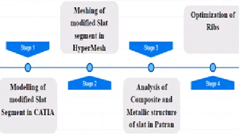
Fig 1: Flow chart of stages of FEM analysis
Fig 1 shows flow chart for the FEM analysis and optimization of the slat section. The work is done in four stages. First stage includes modeling of modified slat segment in CATIA. Second stage includes meshing of Slat segment in Hypermesh. In third stage analysis of composite section and metallic structure of slat segment in Patran and fourth stage includes optimization of ribs.
2.
MODELLING
Models are created with the assistance of 2 Dimensional AutoCAD illustrations given by the organization. In this project work CATIA V5 is used. CATIA version 5 Part Design software makes it possible to design accurate 3D mechanical parts with a natural and adaptable UI, from drawing in a get together setting to iterative point by point plan. CATIA V5 part configuration can be utilized with co activity with other present or future friend items in the following CATIA V5 generative Drafting. Part configuration incorporates: Solid modeling intentions, Basic sketch based features, Options- part design, Creating pads, Creating multiple pads, Creating pockets, Creating multiple pockets. Overall Slat is divided into two sections i.e. slat section 1 and 2. . Fig 1 and Fig 2 shows the modeling of slat section 1. Slat section 1 consist of 31 ribs. Each ribs have different height according to the skin contour. Slat section includes many different components like ribs, doubler, angles, base plate, etc. those are collectively covered with skin cover, we can see model of slat section with skin in fig 2
Fig 3: Complete model of slat section 1 with skin cover
3.
MESHING
Commercial accessible limited component programming HyperMesh has been utilized as the fundamental Finite component investigation programming for doing this work. HyperMesh comprises of a pre-handling module which is utilized to characterize the issue geometry and information, a preparing module to amass and understand the limited components conditions and a post preparing module to yield the unraveled conditions and figure extra amounts of intrigue. Fig 3 and Fig 4 gives the total meshing of slat segment. Here we can see the total assembly of different parts meshed by taking their midsurfaces.In Fig 4 we can see the meshed skin cover of slat segment.
Fig 4: Meshed slat section 1
Fig 5: Meshed slat section with skin
4. ANALYSIS AND RESULTS
Patranis used for the analysis of model of slat. Comparison between the results obtained can be established for metallic and composite structure of slat section 1. Fig 5 and Fig 6 shows the maximum and minimum value of displacement for composite and metallic structure. Similarly Fig 7 and Fig 8 gives the maximum and minimum stresses value of composite and metallic structure. Table 1 and Table 2 consist of material properties for Kevlar and Aluminium
Table1: Material properties of Kevlar
Equation of state Orthotropic Sub equation of state Polynomial Reference density (g/cm2) 1.65
Young’s modulus 1.948000E+006 Poisson’s ratio 0.08000
Shear modulus 2.230000e+005
Strength Elastic
Tensile failure stress 1.2000E+006
Erosion strain 1.2
Table 1 includes material properties of Kevlar. Parameters like young’s modulus, poisson’s ratio, shear modulus, strength etc are mentioned which are necessary for analysis.
Table 2: Material properties of Aluminium
Type Alloy D19CHAT
Strength (kg/mm2) 52 Density (g/cm2) 2.78 Poisson’s ratio 0.3 Percentage elongation 6%
Table 2 consist of material properties for aluminium. Type is D19CHAT which indicates it is composition of chromium, lithium and magnesium. Other parameters are strength, density, poisson’s ratio, etc.
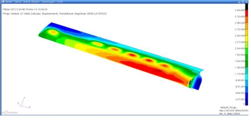
Fig 6: Displacement of metallic structure.
In Fig 6 it is observed that there is maximum displacement on the top of the rib indicated by red color. The value of displacement in that region is in range of 3.32 mm.
Fig 7: Displacement of composite structure
Fig 8:Stresses of metallic structure
Fig 8 shows stress values for metallic structure. We observe that structure is safe. The stress value observed for the structure here is 92.42 N/mm2 and maximum allowable stress of structure is 276.642 N/mm2.
Fig 9:Stresses of composite structure
Fig 9 shows the stress result of composite section in slat segment. We observe that the maximum stress for structure is 110.81 N/mm2 and maximum allowable stress of structure is 117.06 N/mm2. The Table 3 shows the maximum stress, minimum stress and deformation values for metallic and composite structures and the variation in stresses and deformation. Deformation limit specified is 3.5 for this structure. For composite structure is 3.4 and for metallic structure its 3.3. Table 1 shows the deformation for both the materials which are within limit. As per results obtained we can conclude that stresses are within limits. As the structure made from both the materials have displacement within the specified limit that is below 3.5 mm. We can use composite material instead of metallic material.
Table 3: Simulation Results
Parameters Metallic Structure Composite Structure Maximum stress (N/mm2) 92.42 110.81
Deformation (mm) 3.32 3.40
5.
SHAPE OPTIMIZATION
Material is removed in standard shape from the center of the ribs. Mainly three shapes viz. trapezoidal, circular and triangular are considered for comparison of stresses, strain and deformation.
Fig 10: perpendicularly applied pressure
Figure 10 shows pressure applied on each rib is 5.77e-003 Mpa. As skin is connected to the edges of the ribs, pressure will act in perpendicular direction. Hence pressure is applied perpendicularly and evenly distributed on edges during optimization.
Fig 11: Material removed
Material removal considered is 40-50%, which results in some random shaped material removal shown in Figure 11. It is difficult to machine such random complex shape therefore standard shapes are considered. Shapes like trapezoid, circle and triangle are considered for comparison of optimization results.
Fig 12. Deformation of modified trapezoidal rib
Fig 13. Strain of modified trapezoidal rib
Figure 13 shows maximum and minimum strain for modified rib cut into trapezoidal cross section area. Maximum strain obtained is 0.00053474. Minimum strain obtained is 4.4048e-7.
Fig 14. Stresses of modified trapezoidal rib
Figure 14 shows the maximum and minimum stress for the modified rib cut intotrapezoidal cross section area. Maximum stress generated is 29.292 and minimum stress generated is 0.031167.
Fig 15. Stresses of circular modified rib
Figure 15 shows the maximum and minimum stress for the modified rib cut into circular cross section area. Maximum stress generated is 19.857 and minimum stress generated is 0.043353.
Fig 16. Strain of circular modified rib
Figure 16 shows maximum and mini strain for the modified rib cut into circular cross section area. Maximum strain obtained is 0.000280. Minimum strain obtained is 8.8671e-7.
Fig 17. Deformation of circular modified rib
Figure 17 shows the total deformation of the modified rib cut into circular cross section area. Total deformation accepted is within 3.4 mm and the results obtained from this analysis shows 0.23218 mm deformation which can be considered within limit.
Fig 18. Stresses of triangular modified rib
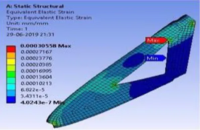
Fig 19. Strain of triagular modified rib
Figure 19 shows maximum and mini strain for the modified rib cut into triangular cross section area. Maximum strain obtained is 0.00030558. Minimum strain obtained is
4.0243e-7.
Fig 20. Deformation of triangular modified rib
Figure 20 shows the total deformation of the modified rib cut into triangular cross section area. Total deformation accepted is within 3.4 mm and the results obtained from this analysis shows 0.33912 mm deformation which can be considered within limit
Table 4 : Comparison of optimized ribs
Parameters Trapezoidal Circular Triangular Deformation
(mm) 0.10189 0.23218 0.33921
Maximum
Stresses (Mpa) 29.292 19.857 20.137 Minimum stress
(Mpa) 0.031167 0.043353 0.022154 Maximum
Strain (mm/mm)
0.00053474 0.000280 0.00030558
Minimun Strain
(mm/mm) 4.4048e-7 8.8671e-7 8.8671e-7
Table 4 implies that rib having circular cut section generate lower stress than the rib having trapezoidal and triangular cut section. Hence, we prefer circular cut section rib for the installation in slat assembly.
6.
CONCLUSION
The FEM analysis of the modified slat structure using composite material is done. It is indicated by the simulation results done using FEM that for identical loading conditions
values of maximum stress and maximum deformation are within the allowable limits. Therefore composite may be used as an alternative to metallic structure. Optimization results indicate that rib having circular cut section has lower stress generated hence it is preferable than the rib having trapezoidal and triangular cutsection.
ACKNOWLEDGEMENTS
I take this opportunity to thank all of those who have generously helped me to give a proper shape to my Project work. I am thankful to my guide prof. Dr.SurbhiRazdan, for the constant support and encouragement .I would like to express my gratitude to Dr. Ratnakar R. Ghorpade, coordinator of M.Tech. Design Engineering for proper guidance for my thesis work.
REFERENCES
[1] Huan Pang, Tianxiang Yu, Bifeng Song ―Failure mechanism analysis and reliability assessment of an aircraft slat‖ School of Aeronautics, Northwestern Polytechnical University Engineering Failure Analysis 60 (261–279), 2016.
[2] TahirYavuz ,EmreKoc,
BahadırKaynak―Hydrodynamics performance of hydrofoil-slat arrangements in 3D analysis‖Baskent University, Department of Mechanical Engineering, Ankara, Turkey. 44-50 (2013).
[3] Paul Okonkwo, Howard Smith ―Review of evolving trends in blended wing body aircraft design‖ Department of Aerospace Engineering, School of Aerospace Transport and Manufacturing, Cranfield University, Bedford, United Kingdom, Progress in Aerospace Sciences 82, 1-23(2016).
[4] ZHAO Qun, DING Yunliang, JIN Haibo,‖ A Layout Optimization Method of Composite Wing Structures Based on Carrying Efficiency Criterion‖, Key Laboratory of Fundamental Science for National Defense-Advanced Design Technology of Flight Vehicle, Nanjing University of Aeronautics and Astronautics, Nanjing, China, 425-433 (2011). [5] Jared R.Hammertona, WeihuaSua, GuomingZhub,
Sean Shan-MinSweica,―Optimum distributed wing shaping and control loads for highly flexible aircraft‖t, Department of Aerospace Engineering and Mechanics, University of Alabama, Tuscaloosa, , United States, 35487-0280 (2018). [5] S. Rana, R. Fangueiro, ―Advanced composites in
aerospace engineering‖, School of Engineering, University of Minho, Portugal, 1-15 (2015).
[6] K.V.N. Gopal, ―Product design for advanced composite materials in aerospace engineering‖, Indian Institute of Technology Madras, Chennai, India. 413-428 (2013).
[7] M. Joshi, U. Chatterjee―Polymer nanocomposite: an advanced material for aerospace applications‖, Indian Institute of Technology, New Delhi, India. 241-264. (2014).
[9] Li Jun, YangWei, ZhangYugang, PeiYang, RenYunsong, Wang Wei, ―Aircraft vulnerability modeling and computation methods based on product structure and CATIA‖ School ofAeronautics,NorthwesternPolytechnicalUniversity, China. Chinese Journal of Aeronautics 26(2); 334-342 (2013).
[10] Sahuck Oh, ―A new triangular mesh repairing method using a mesh distortion energy minimization-based mesh flattening method‖ School of Aerospace and Mechanical Engineering, Korea Aerospace University, Goyang, Republic of Korea. Advancesin Engineering Software 131; 48-59(2019).
[12] R. Durand, B.G. Pantoja-Rosero, V. Oliveira, ―A general mesh smoothing method for finite elements, Department of Civil Engineering, University of Brasilia, Campus Darcy Ribeiro, Brasilia, Brazil, Finite Elements in Analysis and Design 158; 17-30(2019).