O R I G I N A L A R T I C L E
Orientation control of cellulose nanofibrils in all-cellulose
composites and mechanical properties of the films
Shuji Fujisawa1• Eiji Togawa1•Noriko Hayashi1
Received: 14 October 2015 / Accepted: 23 November 2015 / Published online: 15 December 2015
ÓThe Japan Wood Research Society 2015
Abstract In this study, highly oriented all-cellulose composite films were successfully prepared by mechanical drawing of water-swollen cellulose nanofibril/regenerated cellulose composite film, and their mechanical properties were investigated by tensile tests. Cellulose nanofibrils with a uniform width of*3 nm and length of the order of a few micrometers were prepared via 2,2,6,6-tetram-ethylpiperidine-1-oxyl-mediated oxidation of wood pulp and successive mechanical treatment. The nanofibrils were then dispersed in a cotton/lithium chloride/N,N -dimethy-lacetamide solution, and all-cellulose composite films were prepared by regenerating the cotton cellulose. The cellu-lose nanofibrils were individually dispersed and success-fully oriented in the film by mechanical drawing, and the orientation parameter of the nanofibrils was as high as 0.80 for a draw ratio of 2.0. Although the Young’s modulus and tensile strength of the films were significantly improved by the mechanical drawing, the reinforcing effect by the ori-ented cellulose nanofibrils in the present all-cellulose composite were not clear, presumably because the cellulose nanofibrils are less compatible with the cellulose matrix in this study.
Keywords NanocelluloseAll-cellulose composite
2,2,6,6-Tetramethylpiperidine-1-oxyl-mediated oxidation
Mechanical drawing
Introduction
Cellulose is the most abundant renewable carbon resource on earth. In nature, cellulose exists as crystalline nanofib-rils [1], and wood cellulose nanofibnanofib-rils have high aspect ratios ([300) with very small widths (*3 nm). Owing to their high crystallinity, nanofibrils exhibit excellent prop-erties such as high Young’s modulus [2–4], high strength [5, 6], and thermal dimensional stability [7]. Therefore, cellulose nanofibrils are promising candidates for use as a reinforcing filler in polymer nanocomposites [8–10]. To take advantage of this reinforcing potential, the dis-persibility, interaction, and orientation of nanofibrils in nanocomposite materials must be enhanced.
All-cellulose nanocomposite, a material in which both reinforcing and matrix phases are composed of cellulose, has been attracting attention over the past decade [11] because of its intrinsic sustainability with excellent com-patibility between the filler and matrix. Nishino et al. [12] first reported on an all-cellulose nanocomposite by partly dissolving ramie fiber in a lithium chloride (LiCl)/N, N -dimethylacetamide (DMAc) solution. In the nanocompos-ite, the dissolved part (matrix) was self-reinforced by remaining crystalline nanofibrils (filler) with good interfa-cial compatibility, and the crystalline part was uniaxially oriented. Therefore, the nanocomposite exhibited high tensile strength and dynamic storage modulus and low thermal expansion coefficient.
Cellulose nanofibrils cannot be individually dispersed easily in all-cellulose composites by partly dissolving native celluloses. However, we have previously applied TEMPO-mediated oxidation as a preparation step for cel-lulose nanofibrils [13, 14] to achieve good dispersion in polymer matrices, such as poly(styrene) [15] and poly(L
-lactic acid) [16,17]. Because of the good dispersibility of
& Shuji Fujisawa
1 Forestry and Forest Products Research Institute,
TEMPO-oxidized cellulose nanofibrils (TOCNs) in poly-mer matrices, the resultant nanocomposites exhibit improved mechanical properties. Taking advantage of the improved dispersibility, the same procedure can be employed to prepare all-cellulose composite materials with excellent mechanical properties because of the better dispersibility.
In this study, all-cellulose composite films were pre-pared using TOCNs as a reinforcing nanofiller. The TOCNs were prepared from wood pulp and individually dispersed in a regenerated cotton cellulose matrix. In the composite films, the TOCNs were oriented by mechanical drawing to improve mechanical properties. In this study we aim first to analyze the relation between the draw ratio and TOCN orientation ratio; secondly we aim to investigate the mechanical properties of the prepared all-cellulose com-posite films.
Experimental
Materials
Cotton linter having an average DP of 1196 was supplied by Asahi Kasei Corporation. TEMPO, a 2 M sodium hypochlorite solution, sodium bromide, LiC1, DMAc, and N,N-dimethylformamide (DMF) were purchased from Wako Pure Chemicals, Co. Ltd., Japan. The LiCl was dried at 105°C, and the DMAc and DMF were stored in the presence of molecular sieves 3A prior to use. Other reagents were used without purification.
Preparaion of cellulose solution in LiCl/DMAc
Cotton linter was soaked in water for 1 day and then sol-vent exchanged through ethanol to DMAc via filtration. A 1 % w/w cellulose solution was prepared by mixing the cotton and 8 % LiCl/DMAc solution. The cellulose solu-tion was purified by filtering through a glass filter.
Preparation of TOCN dispersion in DMF
Softwood bleached kraft pulp was oxidized by TEMPO/ NaClO/NaBr system at pH 10 [18]. The carboxylate con-tent of the oxidized pulp was determined to be 1.4 mmol g-1 by electric conductivity titration. The oxi-dized pulp was then subjected to mechanical treatments in water using a blender (Ace homogenizer, Nihonseiki Ltd.) and an ultrasonic homogenizer (VP-300N, TAITEC). The TOCN dispersion in water was purified by filtration through a glass filter. Thereafter, 1 M HCl was added to the TOCN dispersion to enhance the dispersibility of TOCNs in DMF through the exchange of the surface sodium
carboxyl groups of the TOCNs with the free carboxyl groups [19]. The dispersion was then converted to a gel. The gel was thoroughly washed with water and then sol-vent exchanged with DMF by centrifugation. The gel was then sonicated to prepare 0.3 % w/w TOCN dispersion in DMF.
Preparation of drawn all-cellulose composite films
The TOCN/DMF dispersion was mixed with the cotton/ LiCl/DMAc solution in different TOCN/dissolved cellu-lose ratios from 0/100 to 50/50. The mixtures were soni-cated for 1 min to obtain homogeneous mixtures. The mixtures were poured into glass Petri dishes and left under saturated humidity for 3 days to obtain composite gels by regenerating cotton cellulose. The gels thus obtained were washed under running water for 3 days to remove LiCl, DMAc, and DMF, and water-swollen TOCN/regenerated cellulose composite films were obtained in high yields (*100 %). The water-swollen films were drawn using a drawing device and dried at room temperature on the device. Drawn all-cellulose composite films with draw ratios of91.5 and92.0 were thus obtained.
Analyses
Approximately 100-nm-thick sections were stained with 1 % uranyl acetate and 2 % lead citrate on a formvar-coated Cu grid. Tensile properties were investigated using a tensile tester (EZ Graph, Shimadzu) equipped with a 500-N load cell. The specimens were tested with a span of 10 mm at a crosshead speed of 1 mm min-1.
Results and discussion
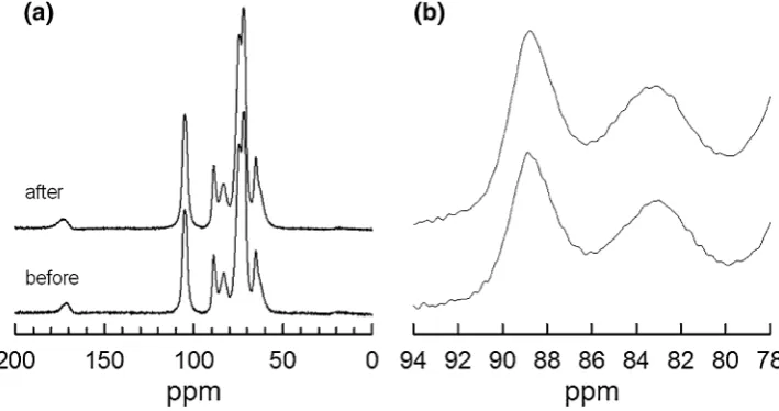
First, to confirm that the crystal structure of the TOCNs was preserved during the preparation process, only the TOCNs were sonicated in 8 % LiCl/DMAc for 5 min, and the mixture was stirred for 1 week, which is a harsher condition than that employed for the present all-cellulose composite preparation. After the treatment, the TOCNs were collected by adding 0.01 M HCl and then washed thoroughly with water. The weight recovery ratio of the TOCNs was*100 %. Figure1 shows the solid-state 13C CP/MAS spectra of the TOCNs before and after the treatment. As can be observed, the crystal structure of the TOCNs is preserved. The cellulose I crystal structure is preserved after the treatment (Fig.1a). Moreover, the crystal width of the TOCNs does not vary after the 8 % LiCl/DMAc treatment. The changes in width can be eval-uated by comparing the total area and crystal region of the C4 signal (Fig.1b) [20–22] because C4 signal intensities are assumed to be quantitative under the present CP con-dition [23]. For the TOCNs, the calculated ratios were the same before and after the treatment, thus indicating that surface chains were not dissolved out of crystal surfaces. This was also confirmed with the X-ray diffraction patterns by calculating the widths using the Sherrer equation (data not shown). It has been reported that TOCNs are not likely to be dissolved in 8 % LiCl/DMAc without complete methyl esterification of surface carboxyl groups [24];
therefore, introduced carboxylate groups enhance the sta-bility of crystalline cellulose nanofibrils against dissolution in LiCl/DMAc. Further, the crystal structure and crystal width of the TOCNs were confirmed to be intact over the course of the preparation.
The orientations of the TOCNs in the all-cellulose composite films were evaluated by WAXD analysis (Fig.2). For cellulose films without the TOCNs, the undrawn films showed isotropic halo at 2h =*20° (Fig.2c), which is typical of amorphous polymer films. After uniaxial drawing of the films, cellulose chains were oriented along the drawing axis [25], and the orientation can be clearly observed in the X-ray diffraction diagrams (Fig.2a, b), where the drawn direction (meridian) is ver-tical. Although the crystallinity is very low, as reported in a previous study [26], these patterns of the drawn films could be attributed to the cellulose II structure with small crystal sizes. The peaks become stronger and sharper as the draw ratio increases to 2.0.
Chain orientations in the films were evaluated by cal-culating the orientation parameter (f) using the azimuthal profiles as follows.
f ¼1
2 3hcos
2/i 1 ð1Þ
where
hcos2/i ¼rIð Þ/ cos
2/sin/d/
rIð Þ/ sin/d/ : ð2Þ
The samples were tilted to the Bragg angle corresponding to the (0 0 4) reflection, and the f value was calculated assuming cylindrical symmetry along the drawing direc-tion. Axial symmetry was assumed with respect to the orientation, and a Gaussian distribution was used to fit the peaks, which was based on the least-squares fitting method. Thef value increases as the draw ratio increases (Fig.2f),
Fig. 1 13C CP/MAS NMR
and the value is as high as 0.93 for films with a draw ratio of 2.0.
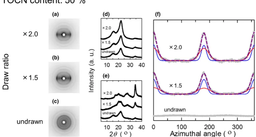
In the all-cellulose composite films, TOCN orientation was successfully induced by the orientation of the regen-erated cellulose matrix. In the case of 50 wt% TOCN, a
typical cellulose I diffraction pattern can be observed in the X-ray diffraction patterns, and the crystalline orientation improves as the draw ratio increases (Fig.3a–e). In Fig.3f, the azimuthal profiles of (004) were decomposed into two Gaussian components, TOCNs (red lines) and regenerated Fig. 2 WAXD results of regenerated cellulose films with different
draw ratios: a–c X-ray diagrams, d, e meridional and equatorial intensity profiles, respectively, andf azimuthal distribution of 004
reflection. Note that azimuthal intensity profiles were fitted with Gaussian peaks (blue lines)
Fig. 3 WAXD results of all-cellulose composite films with 50 % TOCNs:a–cX-ray diagrams,d,emeridional and equatorial intensity profiles, respectively, andfazimuthal distribution of 004 reflection
cellulose matrix (blue lines), assuming that the orientation parameters of the regenerated cellulose matrix are 0.90 and 0.93 at draw ratios of 1.5 and 2.0, respectively, as shown in Fig.2f. The orientation parameters for the TOCNs with draw ratios of 1.5 and 2.0 were 0.68 and 0.80, respectively. Because the f values are similar for composites with 10–40 wt% TOCN contents, the orientation of the TOCNs can be controlled at any content. These orientation parameters are slightly higher than those of nanocrys-tal/carboxymethyl cellulose films [27], cold-drawn TEMPO-oxidized nanofibrillated cellulose films [28], and drawn self-reinforced cellulose films [29]. Therefore, the TOCNs with high aspect ratios were successfully oriented at high degrees by simple mechanical drawing.
The orientation behavior of the TOCNs was also evaluated by SAXS measurement. Figure4 shows the SAXS results for films with 0 and 50 wt% TOCNs with different draw ratios of up to 2.0. The films without the TOCNs exhibited obscure scattering patterns in this measurement range even after being drawn (Fig.4a). The azimuthal intensity distribution was integrated along the circle (2h =1.5°–1.8°, which corresponds to 5–6 nm period in real space) shown in Fig.4, and the films did not exhibit significant peaks in the azimuthal distribution. On the other hand, the drawn all-cellulose composites with 50 wt% TOCNs with isotropic components exhib-ited stronger scattering streaks perpendicular to the drawing direction. The azimuthal intensity profiles were fitted by Gaussian peaks, and the full width at half maximum of the fitted peaks decreased from 53.2° to 48.4° as the draw ratio increased from 1.5 to 2.0. Note that the volume of the cellulose matrix was adjusted to be the same in all samples. The stronger scattering of the composite was caused by the TOCNs with a uniform width of *3 nm. Therefore, the orientation behavior of the TOCNs was successfully analyzed by employing SAXS measurement.
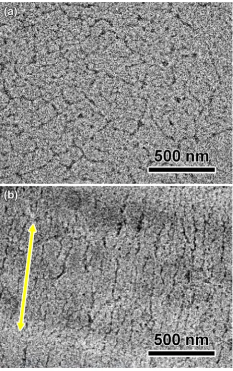
We also employed TEM observation to confirm the orientation of the TOCNs in the all-cellulose composite films. Figure5shows lengthwise sectional TEM images of the composite films with 10 wt% TOCNs. In the drawn Fig. 4 SAXD results ofaregenerated cellulose films andball-cellulose composite films with 50 wt% TOCNs. Note that azimuthal intensity profiles from the center were fitted with Gaussian peaks
films (Fig.5b), individually dispersed TOCNs are homo-geneously and widely distributed and well aligned along the drawing direction, whereas in the undrawn films, the TOCNs are randomly oriented (Fig.5a). The orientation direction corresponds to that of the mechanical drawing direction, and the aspect ratios of the TOCNs remain high even after mechanical drawing.
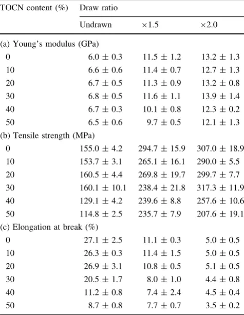
The mechanical properties of the all-cellulose composite films were characterized by tensile testing along the drawing axis. The Young’s modulus and tensile strength of the films were significantly improved by mechanical drawing, whereas the ductility was reduced (Table1; Fig.6). However, the mechanical properties of the drawn all-cellulose nanocomposites were largely depend on those of the cellulose matrix, and the reinforcement effect by the oriented TOCNs were not obvious. Although the modulus and strength values of the film with 30 % TOCN were 13.9 GPa and 317 MPa, respectively, these values are inferior to those of uniaxially oriented all-cellulose composite films reported in previous studies [12, 29–31], although the TOCNs are more oriented in the films as discussed above. Gindl and Keckes reported that the Young’s modulus and tensile strength of drawn all-cellulose composite films can
be significantly improved to up to 33 GPa and 430 MPa, respectively, by adding 25 % commercial microcrystalline cellulose as a filler [29]. These results indicate that TOCNs are less compatible with the cellulose matrix in this study, presumably because of introduced carboxyl groups on the surfaces; when the TOCN content is further increased to up to 50 %, the interface between TOCNs and cellulose matrix significantly increased, and the interface acted as crack initiation site during the tensile test. However, TOCN surfaces can be easily modified using surface carboxyl groups as selective modification sites [14,32,33]. In future work, we aim to control mechanical properties by tuning the interfacial interaction with surface modification.
Conclusions
In conclusion, the orientation of the TOCNs in the all-cellulose composite films was successfully controlled by mechanical drawing, and the oriented TOCNs acted as a reinforcing filler for the films. The orientation parameters of the TOCNs were as high as 0.80 for a draw ratio of 2.0. Further, TEM observations confirmed that the TOCNs were individually dispersed in the film and highly oriented along the drawing axis. The Young’s modulus and tensile strength of the film were significantly improved as the draw ratio was increased to up to 2.0. Although TOCNs were highly oriented in the films, the reinforcing effect by the orientation were not clear in the present all-cellulose composite, presumably because TOCNs are less compati-ble with the cellulose matrix in this study. However, the mechanical properties of this composite system can be easily varied by altering the TOCN content and/or draw ratio. Moreover, this technique can be employed for the orientation control of other nanomaterials such as carbon nanotubes and silver nanorods, thus providing a potential platform for developing bio-based nanocomposites with excellent mechanical properties and high functionality. Fig. 6 Representative stress–strain curves for all-cellulose composite films with 30 wt% TOCNs at different draw ratios
Table 1 Mechanical properties of all-cellulose composite films: (a) Young’s modulus, (b) tensile strength, and (c) elongation at break with standard deviation
TOCN content (%) Draw ratio
Undrawn 91.5 92.0
(a) Young’s modulus (GPa)
0 6.0±0.3 11.5±1.2 13.2±1.3
10 6.6±0.6 11.4±0.7 12.7±1.3
20 6.7±0.5 11.3±0.9 13.2±0.8
30 6.8±0.5 11.6±1.1 13.9±1.4
40 6.7±0.3 10.1±0.8 12.3±0.2
50 6.5±0.6 9.7±0.5 12.1±1.3
(b) Tensile strength (MPa)
0 155.0±4.2 294.7±15.9 307.0±18.9
10 153.7±3.1 265.1±16.1 290.0±5.5
20 160.5±4.4 269.8±19.7 299.7±7.7
30 160.1±10.1 238.4±21.8 317.3±11.9
40 129.1±4.2 239.6±8.8 257.6±10.6
50 114.8±2.5 235.7±7.9 207.6±19.1
(c) Elongation at break (%)
0 27.1±2.5 11.1±0.3 5.0±0.5
10 26.3±0.3 11.4±1.5 5.0±0.5
20 26.9±3.1 10.8±0.5 5.1±0.5
30 20.5±1.7 8.0±1.0 4.4±0.8
40 11.2±0.8 7.4±2.4 4.5±0.4
Acknowledgments This research was supported by Grants-in-Aid for Scientific Research (Grant No. 26-7774) from the Japan Society for the Promotion of Science. The SAXD data were collected at Shimadzu Corp.
References
1. Nishiyama Y (2009) Structure and properties of the cellulose microfibril. J Wood Sci 55:241–249
2. Sakurada I, Nukushina Y, Ito T (1962) Experimental determi-nation of the elastic modulus of crystalline regions in oriented polymers. J Polym Sci 57:651–660
3. Sturcova A, Davies GR, Eichhorn SJ (2005) Elastic modulus and stress-transfer properties of tunicate cellulose whiskers. Biomacromolecules 6:1055–1061
4. Iwamoto S, Kai W, Isogai A, Iwata T (2009) Elastic modulus of single cellulose microfibrils from tunicate measured by atomic force microscopy. Biomacromolecules 10:2571–2576
5. Saito T, Kuramae R, Wohlert J, Berglund LA, Isogai A (2013) An ultrastrong nanofibrillar biomaterial: the strength of single cel-lulose nanofibrils revealed via sonication-induced fragmentation. Biomacromolecules 14:248–253
6. Wu XW, Moon RJ, Martini A (2014) Tensile strength of Ib crystalline cellulose predicted by molecular dynamics simulation. Cellulose 21:2233–2245
7. Hori R, Wada M (2005) The thermal expansion of wood cellulose crystals. Cellulose 12:479–484
8. Samir MASA, Alloin F, Dufresne A (2005) Review of recent research into cellulosic whiskers, their properties and their appli-cation in nanocomposite field. Biomacromolecules 6:612–626 9. Berglund LA, Peijs T (2010) Cellulose biocomposites-from bulk
moldings to nanostructured systems. MRS Bull 35:201–207 10. Eichhorn SJ, Dufresne A, Aranguren M, Marcovich NE,
Capa-dona JR, Rowan SJ, Weder C, Thielemans W, Roman M, Ren-neckar S, Gindl W, Veigel S, Keckes J, Yano H, Abe K, Nogi M, Nakagaito AN, Mangalam A, Simonsen J, Benight AS, Bismarck A, Berglund LA, Peijs T (2010) Review: current international research into cellulose nanofibres and nanocomposites. J Mater Sci 45:1–33
11. Huber T, Mussig J, Curnow O, Pang SS, Bickerton S, Staiger MP (2012) A critical review of all-cellulose composites. J Mater Sci 47:1171–1186
12. Nishino T, Matsuda I, Hirao K (2004) All-cellulose composite. Macromolecules 37:7683–7687
13. Saito T, Nishiyama Y, Putaux JL, Vignon M, Isogai A (2006) Homogeneous suspensions of individualized microfibrils from TEMPO-catalyzed oxidation of native cellulose. Biomacro-molecules 7:1687–1691
14. Saito T, Hirota M, Tamura N, Kimura S, Fukuzumi H, Heux L, Isogai A (2009) Individualization of nano-sized plant cellulose fibrils by direct surface carboxylation using TEMPO catalyst under neutral conditions. Biomacromolecules 10:1992–1996 15. Fujisawa S, Ikeuchi T, Takeuchi M, Saito T, Isogai A (2012)
Superior reinforcement effect of TEMPO-oxidized cellulose nanofibrils in polystyrene matrix: optical, thermal, and mechan-ical studies. Biomacromolecules 13:2188–2194
16. Fujisawa S, Saito T, Kimura S, Iwata T, Isogai A (2013) Surface engineering of ultrafine cellulose nanofibrils toward polymer nanocomposite materials. Biomacromolecules 14:1541–1546 17. Fujisawa S, Saito T, Kimura S, Iwata T, Isogai A (2014)
Com-parison of mechanical reinforcement effects of surface-modified cellulose nanofibrils and carbon nanotubes in PLLA composites. Compos Sci Technol 90:96–101
18. Isogai A, Saito T, Fukuzumi H (2011) TEMPO-oxidized cellu-lose nanofibers. Nanoscale 3:71–85
19. Okita Y, Fujisawa S, Saito T, Isogai A (2011) TEMPO-oxidized cellulose nanofibrils dispersed in organic solvents. Biomacro-molecules 12:518–522
20. Heux L, Dinand E, Vignon MR (1999) Structural aspects in ultrathin cellulose microfibrils followed by13C CP-MAS NMR. Carbohydr Polym 40:115–124
21. Montanari S, Rountani M, Heux L, Vignon MR (2005) Topochemistry of carboxylated cellulose nanocrystals resulting from TEMPO-mediated oxidation. Macromolecules 38:1665–1671 22. Wickholm K, Larsson PT, Iversen T (1998) Assignment of non-crystalline forms in cellulose I by CP/MAS 13C NMR spec-troscopy. Carbohydr Res 312:123–129
23. Larsson PT, Wickholm K, Iversen T (1997) A CP/MAS 13C NMR investigation of molecular ordering in celluloses. Carbo-hydr Res 302:19–25
24. Hiraoki R, Fukuzumi H, Ono Y, Saito T, Isogai A (2014) SEC-MALLS analysis of TEMPO-oxidized celluloses using methyla-tion of carboxyl groups. Cellulose 21:167–176
25. Togawa E, Kondo T (1999) Change of morphological properties in drawing water-swollen cellulose films prepared from organic solutions. A view of molecular orientation in the drawing process. J Polym Sci Pol Phys 37:451–459
26. Togawa E, Kondo T (2007) Unique structural characteristics of nernatic ordered cellulose-stability in water and its facile trans-formation. J Polym Sci Pol Phys 45:2850–2859
27. Wang BC, Torres-Rendon JG, Yu JC, Zhang YM, Walther A (2015) Aligned bioinspired cellulose nanocrystal-based nanocomposites with synergetic mechanical properties and improved hygromechanical performance. ACS Appl Mater Interfaces 7:4595–4607
28. Sehaqui H, Ezekiel Mushi N, Morimune S, Salajkova´ M, Nishino T, Berglund LA (2012) Cellulose nanofiber orientation in nanopaper and nanocomposites by cold drawing. ACS Appl Mater Interfaces 4:1043–1049
29. Gindl W, Keckes J (2007) Drawing of self-reinforced cellulose films. J Appl Polym Sci 103:2703–2708
30. Qin C, Soykeabkaew N, Xiuyuan N, Peijs T (2008) The effect of fibre volume fraction and mercerization on the properties of all-cellulose composites. Carbohydr Polym 71:458–467
31. Soykeabkaew N, Arimoto N, Nishino T, Peijs T (2008) All-cel-lulose composites by surface selective dissolution of aligned ligno-cellulosic fibres. Compos Sci Technol 68:2201–2207 32. Araki J, Wada M, Kuga S (2001) Steric stabilization of a
cellu-lose microcrystal suspension by poly(ethylene glycol) grafting. Langmuir 17:21–27