Z h i - H u i W u • T a k e s h i F u r u n o • H i r o s h i Y o s h i h a r a
Calculation models of pressure and position of curved laminated veneer
lumber in molds during pressing*
Received: February 13, 1998 / Accepted: September 24, 1998 A b s t r a c t Curved laminated veneer lumber (LVL) for use in furniture-making was produced from glue-coated pieces of rotary-cut veneers that were assembled and pressed be- tween molds. Pressure was applied until glue-lines were set and finally held in an assembly of the desired curvature. Pressure was an important factor during pressing of curved LVL. In this study we deduced some equations for design- ing the shape of molds and calculating the total pressure from the mechanics. The results are summarized as follows: (1) The position angle of every section of curved LVL as- sembly in molds on the horizontal and the total pressure during pressing can be calculated in relation to the shapes and dimensions of the curved LVL. (2) The pressure distri- butions in the glue-line measured using pressure-sensitive film were in good agreement with the glue-line unit pressure provided for the experiment and calculation. Therefore, the equations deduced in this study were suitable for calculating the position angle and pressure of curved L V L in molds. (3) The total pressure on curved LVL was greater than the pressure on straight LVL. The total pressure consisted of the pressure on the glue-lines of straight L V L with the same length and width as curved LVL plus the supplementary pressure needed to bend the veneers. (4) The total pres- sures and position angles of curved L V L in molds were affected by the shape, bent angle, and length of each section of curved LVL.
Z.-H. Wu ~ . T. Furuno ( ~ ) . H. Yoshihara
Faculty of Science and Engineering, Shimane University, Matsue 690-8504, Japan
Tel. +81-852-32-6563; Fax +81-852-32-6123 e-mail: [email protected]
Present address:
College of Wood Science and Technology, Nanjing Forestry Univer- sity, Nanjing 210037, China
* The outline of this study was presented at the 48th annual meeting of the Japan Wood Research Society, Shizuoka, April 3, 1998
K e y w o r d s Curved LVL • Mold • Position angle • Pressure
Introduction
When making and designing modern furniture, curved lami- nated veneer lumber (LVL) can provide a variety of func- tional and aesthetically pleasing wood members for furniture such as chairs, sofas, and tables. 1'2 The method used to produce curved LVL for use in furniture was to press the veneers in molds by bending and gluing and keep them at room temperature or at elevated temperatures. 1-3 The pressure was applied until glue-lines were set and finally held in an assembly of the desired curvature. Curved LVL members can be easily formed into many curved shapes (e.g., L, V, G, U, S, Z, O, h, X styles) with a small radius of curvature of the veneers during the bending and gluing operation. The position of curved LVL in molds, the shape of molds, and the pressure on glue-lines have important effects on the quality of curved LVL during pressing. 4-8
b
C 214
L
-{I
/
I
Pm
P2u
\
L
/
. . . . . ]
Y
£
3 t15+h+15 PI 15+h+151 } 12
v
/
/
J
radius of curvature was small, the curved part looked like the crossed part of two straight lines. To control the position of curved L V L in molds, the pressure of the glue-line, and the thickness of the curved L V L and to stabilize molds and not let them move horizontally during pressing, the sum of the horizontal pressures (Pro =
BpLlsinal, P2H =
BpL2sina2)
on two sections should be zero. Therefore, theequation for the sum of the horizontal pressures can be written as follows:
L1 sinai - L2 sina 2 = 0 (1)
where a I and a2 are the position angles of two sections of L- or V-style curved L V L in molds on the horizontal; L1 and L2 are the lengths of two sections; B is the width of curved LVL; and p is the unit pressure on the glue-line.
The relation between 0~1, a2, and the bent angle (Y) of curved L V L is given as
Ct 2 = 180 ° -- y - - (Z 1 (2)
F r o m Eqs. (1) and (2), the position angle a~ of curved L V L in molds is represented as follows:
a~ = t a n - ' ( / < L2sin7 /
-
L2
cost)
(3)
Pressures can be deduced f r o m the mechanics as follows:
1
; L ~ " P : B P ( c L 1 + cosL2ct2 (4)
Po : Bp(L~ + L2)
(5)and
I_1
+
(6)
AP = BP[\ cosal
coso~L ~ where P is the total pressure of curved L V L in molds; P0 is
~ff a~ a2 the pressure of straight L V L when the total length
and width were the same as those of the curved LVL; and
y
..~.
A P
is the supplementary pressure or the difference in the-- pressures applied to curved L V L and straight L V L during
< L ~ pressing.
Fig. 1. Shape of molds and positions and pressures of curved LVLs. a L or V style, b U style, c Z style. P, total pressure; Pz, P2, P> normal pressures on three sections of curved LVL; Pro, P2H, P 3 H , horizontal pressures; P~, P;, P', vertical pressures; B, width of curved LVL; L1, L2, L3, three section lengths; 7, 71, Y> bent angles; at, % a3, position angles. The black line was curved LVL (thickness of h) and electrodes (thick- ness of 1.5 ram) between the male mold and female mold
Theories and deductions
Position and pressure of L-style or V-style curved L V L in molds
The shape of the molds and the position of L- or V-style curved L V L in molds are shown in Fig. l a . 4'5 W h e n the
Position and pressure of U-style curved L V L in molds The U-style curved L V L is m a d e by whole male and female molds with all the pressure in one direction. T h e shape of these molds and the position of curved L V L in them are shown in Fig. l b . 4 As stated above, to stabilize the molds and not allow them to move horizontally during pressing, the sum of the horizontal pressures on three sections should be zero. Therefore, the equation of the sum of the horizon- tal pressures is as follows:
T h e relations between a~, a2, (z 3 and the bent angles
( ~ 1 , I ;/2) of curved L V L can be given as LVL
121~ = 1 8 0 ° - - ;/1 - - (Zl (8) n o .
I
and !
a? = 360 ° - ;/i ;/z al (9)
2
From Eqs. (7), (8), and (9), the position angle al of 3
curved L V L in molds is represented as follows: 4
5 6
a, = tan-l{-L1L2siny---21-- L3 sin(;/1 + ;/2) ~ ( 1 0 ) 7
9
10 Pressure equations also can be represented as:
P =
B F C 1 COS C62 COS (7B
Poi = Bp(L~ + L2 + L3) (12) and
and
A = Bp c ~ cosae
- - ( C 1 -H L 2 @ L3) }
c o s a 3 (13)
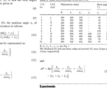
Table 1. Shape and dimensions of curved LVLs
LVL Dimensions (mm) Bent angle
style (°)
B L~ L 2 L 3 71 72
k 400 280 320 - 95 -
k 150 500 700 - 95 -
V 400 420 420 - 45 -
V 300 600 600 - 60 -
k 300 720 720 - 90 -
L 300 650 650 - 150 -
U 300 600 450 600 115 115
U 300 700 400 600 108 120
Z 300 700 400 220 94 105
Z 300 500 420 450 95 95
B, L1, L2, L> 71, 72: see Fig. 1
The thickness (h) and curvature radius of curved L V L were 22 m m and 42 mm, respectively
l(
* L2 +
1
A P = B p [ k , c o s a I C O S a 2 COSIR3
+
L3)}
(20)
Experiments
PoSition and pressure of Z-style curved L V L in molds
Tl~e Z-style curved L V L is made by whole male and female mglds with the total pressure in one direction. The shapes of ]these molds and the position of the curved L V L in the
mdlds are shown in Fig. lC. 4 AS stated above, to stabilize
thd molds and not allow them to move horizontally during pr@sing, the equation of the sum of the horizontal pressures on lthree sections and the relations between %, %, a3 and
I
beot angles (;/1, ;/2) of Z-style curved L V L can be written as follows:
L1 Sinai - L2 sina2 + L3 sina3 = 0 (14)
!
a 2 ~- 1 8 0 ° - - ;/1 - - 0~1
(15)
and
I
a3 ~ ;/1 - ;/2 + al (16)
The position angle al of curved L V L in molds and the]pressures can be deduced from Eqs. (14), (15), and (16!.
a l ~ t a n - l { - L 2 s i n ; / 1 - L 3 s i n ( ; / 1 - ; / 2 ) } ( 1 7 )
i L1 - L2 c°s;/~ + L3 c ° s ( ;/1 -- ;/2)
P -- U p + + •
(18)
. COS(Z1 COSa 2 COSCC 3
I I
P0 ~ B P ( L 1 q- L2 -? L3) ( 1 9 )
I
Shape and dimensions of curved L V L
The shapes of the curved LVLs produced here were L, V, U, and Z styles, as shown as in Fig. 1. The thickness and mois- ture content of rotary-cut veneers produced from massion
pine (Pinus massoniana Lamb.) were 1.2 m m and 8 % - 1 2 % ,
respectively. The type of glue used in this study was urea formaldehyde (UF) resin with a solid content of 61%-62%. The amount of the adhesives applied by a hand roller to the veneers was 200g/m 2 (single spread)/'3 There were 22 ve- neers, so the curved L V L was maintained at 2 2 m m thick- ness. The inside curvature radius of curved L V L in the curved part was 42 ram. The shapes, bent angles, and dimen- sions of curved LVLs are shown in Table 1.
Molds and pressure
216
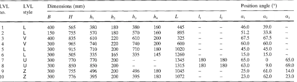
Table 2. Dimensions of molds and positions of curved LVLs in molds
LVL LVL Dimensions (mm) Position angle (°)
no. style
B H hi h2 h3 h4 L 11 ~ a~ a2 a3
1 k 400 565 380 180 380 160 445 - - 46.0 39.0
2 k 150 755 570 180 570 160 895 - - 51.2 33.8
3 V 400 835 610 220 610 200 325 - - 67.5 67.5
4 V 300 965 740 220 740 200 600 - - 60,0 60.0
5 k 300 915 710 200 710 180 1020 - - 45.0 45.0
6 k 300 505 335 165 335 145 1260 - - 15.0 15.0
7 U 300 770 770 200 - - 1345 180 180 65.0 0
8 U 300 850 850 200 - - 1315 180 180 63.0 9.0
9 Z 300 755 496 200 496 180 1045 - - 25.0 61.0
10 Z 300 776 395 200 395 180 1072 - - 23.0 62.0
65.0 69.0 14.0 23.0 B, H, hi, h2, h3, h4, L, lz, l 2, al, a2, a3: see Fig. 1
The thickness (h) and curvature radius of the curved LVL were the same as those in Table 1. The angles of molds (y~, ~2) were the same as those of the curved LVLs in Table 1
Effect of factors on the position and p r e s s u r e of curved L V L in m o l d s
The p r e s s u r e distributions in the glue-line of each section of the curved L V L s were m e a s u r e d using pressure-sensitive film. n'~2 T h e glue-line unit p r e s s u r e (p = 1 M P a ) p r o v i d e d for the e x p e r i m e n t and calculation was c o m p a r e d with the e x p e r i m e n t a l results. F r o m the calculated results using the equations d e d u c e d u n d e r the various curved L V L shapes, the effects of the m a i n factors, such as the b e n t angle (,/,,) and the length (L,) of each section of curved L V L , on the position angle and pressure of curved L V L in m o l d s were studied.
Results and discussion
S h a p e of m o l d and p o s i t i o n of curved L V L in molds T h e p o s i t i o n of the curved L V L in molds could b e ex- p r e s s e d by the p o s i t i o n angles (a~s) of each section of curved L V L on the horizontal. First, these angles w e r e cal- c u l a t e d using Eqs. (2), (3), (8)-(10), and (15)-(17) d e d u c e d f r o m the m e c h a n i c a l theory. T h e n the w o o d e n m o l d s w e r e designed according to the b e n t angles (Tns), lengths (Lns), and p o s i t i o n angles (ans) of each section of curved LVL. T h e p a r a m e t e r s of the shapes of m o l d s and the positions of curved L V L in m o l d s for the various curved L V L shapes (k, V, U, and Z) are shown in T a b l e 2.
A c c o r d i n g to the d a t a in T a b l e 2, the end positions of the two sections of k-, V-, and Z-style curved L V L s in molds on the h o r i z o n t a l were the s a m e (h~ = h3). In L- or V-style curved L V L , according to T a b l e s 1 and 2, the p o s i t i o n angles (al, a2) of two sections of curved L V L in m o l d s were similar to each o t h e r w h e n the lengths (L1, L2) of the two sections were the same. W h e n the length (L 2 in T a b l e 1) of one section of k-style curved L V L was g r e a t e r t h a n that of a n o t h e r section, the p o s i t i o n angle ( a 2 in T a b l e 2) of this section was smaller t h a n that of the o t h e r section. T h e posi- tion angles ( a l and aa in T a b l e 2) of L- or V-style curved
L V L in m o l d s d e c r e a s e d with an increase in the b e n t angle (Yl in T a b l e 1) of the curved L V L .
I n U-style curved L V L , w h e n the b e n t angles (~1, 9~2) and lengths (L~, L3) of two side sections w e r e the same, the p o s i t i o n angles (a~, a3) of the two side sections of curved L V L in m o l d s w e r e the same. T h e p o s i t i o n angle (%) of the c e n t e r section of curved L V L in m o l d s was zero.
In Z-style curved L V L , the p o s i t i o n angles (al, %) of two side sections of curved L V L in m o l d s were the s a m e w h e n the b e n t angles ( ~ , ;/2) of curved L V L w e r e the same. T h e p o s i t i o n angle (%) of the c e n t e r section of curved L V L in molds, however, was not zero.
Pressures of curved L V L in m o l d s
T h e pressures (P, P0) and s u p p l e m e n t a r y p r e s s u r e (AP) were c a l c u l a t e d using Eqs. (4)-(6), (11)-(13), and (18)-(20) d e d u c e d f r o m the m e c h a n i c a l theory. T h e practical pres- sure distributions (Pl, P2,
P3)
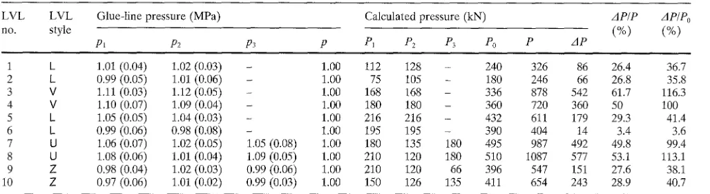
in the glue-line of each section of curved L V L w e r e m e a s u r e d using pressure-sensitive film. 11'12 T h e glue-line unit p r e s s u r e (p = 1 M P a ) p r o v i d e d for the e x p e r i m e n t and calculation and the e x p e r i m e n t a l results w e r e c o m p a r e d . T h e p e r c e n t s (AP/P, AP/Po) of s u p p l e m e n t a r y p r e s s u r e a d d e d to the t o t a l p r e s s u r e are shown in T a b l e 3.A c c o r d i n g to the d a t a in T a b l e 3, the unit p r e s s u r e distri- butions (Pl, P2, P3) in the glue-line m e a s u r e d using p r e s s u r e - sensitive film w e r e in g o o d a g r e e m e n t with the glue-line unit p r e s s u r e (1 M P a ) p r o v i d e d for the e x p e r i m e n t and cal- culation when the total pressures (P) of the calculation using Eqs. (4), (11), and (18) w e r e applied. Thus, the equa- tions d e d u c e d in this study were suitable for calculating the position angle and p r e s s u r e of curved L V L in molds. T h e e q u a t i o n r e p r e s e n t i n g the total p r e s s u r e (P) can be w r i t t e n as:
P = Bp~..(Ln/cosa~) (21)
Table 3. Pressures of curved LVL in molds
LVL LVL Glue-line pressure (MPa) Calculated pressure (kN) AP/P AP/Po
no. style (%) (%)
Pl P2 193 P P1 P2 ]93 Po P AP
1 k 1.01 (0.04) 1.02 (0.03) - 1.00 112 128 - 240 326 86 26.4 36.7
2 L 0.99 (0.05) 1.01 (0.06) - 1.00 75 105 - 180 246 66 26.8 35.8
3 V 1.11 (0.03) 1.12 (0.05) - 1.00 168 168 - 336 878 542 61.7 116.3
4 V 1.10 (0.07) 1.09 (0.04) - 1.00 180 180 - 360 720 360 50 100
5 1 1.05 (0.05) 1.04 (0.03) - 1.00 216 216 - 432 611 179 29.3 41.4
6 k 0.99 (0.06) 0.98 (0.08) - 1.00 195 195 - 390 404 14 3.4 3,6
7 U 1.06 (0.07) 1.02 (0.05) 1.05 (0.08) 1.00 180 135 180 495 987 492 49.8 99.4
8 U 1.08 (0.06) 1.01 (0.04) 1.09 (0.05) 1.00 210 120 180 510 1087 577 53.1 113.1
9 Z 0.98 (0.04) 1.02 (0.03) 0.99 (0.06) 1.00 210 120 66 396 547 151 27.6 38.1
10 Z 0.97 (0.06) 1.01 (0.02) 0.99 (0.03) 1.00 150 126 135 411 654 243 28.9 40.7
p~, pz, p> experimental measurement values of the glue-line unit pressure for each section of curved LVL; p, provided glue-line unit pressure for experiment and calculation; P~, Pz, P> calculated pressures in each section of curved LVL (P1 = BpLI; P2 = BpL2; P3 = BpL3; B, L~, L2, L> see Fig. 1); P, Po, AP, calculated pressures with Eqs. (3)-(5), (9)-(11), (15)-(17)
Each measurement value is the average of five tests. Values in parentheses represent standard deviations
tions of the curved LVL, and % and L~ are the position angle and length of each section.
As shown in Table 3, the total pressure (P) on curved L V L was greater than the pressure (P0) on straight L V L that the total length and width were the same as those of the curved LVL. The total pressure (P) consisted of the glue- line pressure (P0) of straight L V L with the same length and width as curved L V L and the supplementary pressure (AP)
n e e d e d to bend the veneers. 2'4
For L_- or Z-style curved L V L the percents of the supple- m e n t a r y pressure added to the pressure on curved L V L in molds, AP/P and AP/Po, were approximately 30% and 40%, respectively (Table 3), when the bent angles (Yl and V2 in Table 1) of curved L V L were 90°-105 °. F o r L.- or V-style curved LVL, the pressure decreased (AP/P from 61.7% to 3.4%; AP/Po from 116.3% to 3.6%) with an increase in the bent angle (V~ in Table 1) of curved L V L from 45 ° to 150 °. For U-style curved LVL, when the curve angles (V~ and ~/2 were approximately 110 °) and the lengths (L~, L3) of two side sections of curved L V L were the same, AP/P and AP/
P0 were almost 50% and 100%, respectively. The supple- mentary pressure (AP) needed to bend the veneers could be said to be approximately equal to the glue-line pressure (P0) of straight L V L with the same length and width as curved
L V L . 13-14
In addition, for Z-style curved LVL, when the two bent angles (y> V2) of curved L V L were the same, the position angles and pressures of curved L V L in molds could be calculated using equations deduced for k- or V-style curved LVL. [The sum of the lengths of two side sections (L~ + L3) was considered to be the length (L~) of k- or V-style curved L V L 4 because two side sections (L~, L3) of the curved L V L were parallel.]
Effect of position and pressure of curved L V L in molds F r o m the equations deduced above, it was apparent that the position angle (%) of curved L V L in molds was affected mainly by the shape and dimensions of the curved LVL, such as the length (Ln) of each section and the bent angle
()/,) of the curved LVL. The total pressure (P) of curved L V L in molds was affected by these factors (L,,, V~,), the width (B) of the curved LVL, and the unit pressure (p) on the glue-line. The supplementary pressure (ziP) needed to bend the veneers, or the difference in the pressure between curved L V L and straight L V L during pressing, also was affected mainly by the length (L,,) of each section and the bent angle (Vn) of the curved LVL.
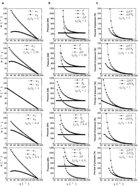
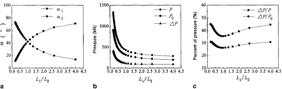
The effects of the main factors such as the length (L1, L2) of each section and bent angle (,/) of 1_- or V-style curved L V L on the position angle and pressure of curved L V L in molds are shown in Figs. 2 and 3. According to these figures, the position angles (al, a2) were the same when the lengths of two sections of curved L V L were the same (LJL2 = 1). The position angle (al) increased with a decrease in the ratio of the two section lengths (LJL2) of l - or V-style curved LVL. In contrast, the position angle (aa) decreased with a decrease in the ratio of the two section lengths (LJL2). In Fig. 2, the position angles (cq, a2) of each section of L- or V- style curved L V L in molds decreased with an increase in the bent angle (V) of curved LVL. W h e n the bent angle (~) of curved L V L decreased from 80 ° to 45 °, the total pressure (P) and supplementary pressure (AP) of curved L V L in molds, and the percent (AP/Po) of the supplementary pres- sure to the pressure n e e d e d for straight L V L increased rapidly and significantly. In Fig. 3, the pressures (P, P0) and supplementary pressure (zIP) n e e d e d for curved L V L in molds increased significantly when the ratio of the two sec- tion lengths (LJL2) of curved L V L decreased from 0.75.
C
120
10o
]"
80"-" 60
40
~ • •
--•--
O~ 1--0--
O~
2L 1 / L ~ = 2
-'5....
20 - " ~ t t .
20 40 60 80 100 120140 160180200 120
100
~-" 80
o
---- 60
- - • - - O~ I
• L1/ L 2 = 1 . 3 3
...
40 " ~ _ ~ • •
20
20 40 60 80 100 120 140 160180200 120
100
~ " 80,
o
60
40
20
- - I - - Og I
--*-- ~ 2
% L~/L 2 = 1
20 40 60 80 100120140160180200
1200
- - • - - p
1000 --•-- P•
--*-- Z~P
~ " 8 0 0 ! L 1 / L 2 = 2 ~
~ 600
!~%.
• 400
200 . . . * . . .
20 40 60 80 100 120 140 160 180200 1200
i __~__ p
i000 - - ~ - - Po
--~-- zSP
800
L 1 / L 2 = 1 . 3 3
600
ft.
400 . ~ . _ _ . . . .
200
1 7'! i17
20 40 60 80 100 120 140 160 180200 1200 z o IL 1000 800 600 400 200
- - n - - p - " P•
- - * - - z S P
\ ~ L 1 / L 2 = 1
\ •
•
. , . . .. . . a_ .. . . _ _ _~,~_..__
. . . • i : , . . .
20 40 60 80 100 120 140 160 180200
g
a
O_
300 ,,
250 200 150 100 50 250
.~ 200
• 150 "6 E 100
8 ~_ so
o
- - , - - z S P / P
- • - ± P / P o
L 1 / L 2 = 2
0 . . . __1. "
20 40 60 80 100120140160180200 300
- - • - - ~ p / p
s o ~ - • - A p / p o
L J L = 1 . 3 3
001-
..\
5o~
"-. ".
, , , l , i , , , n ,
O0 40 60 80 i00 120140 160-f80'200
~oo[.~
- . -
~P/P
2~° I ~.
- ' - ~P/Po
2ootl
L,/L2=I
is° I
%,.
lOO~. %
s o T " "
"•
0 [ ' ' ~ - 1.
20 40 60 80 100120140160180200
120,
12001 ! i 300 .... .
- - m - - ~ i
lOO _ . _ ~ lOOO - - ~'-" 2 ' ° I / - . - Ap/Po
....
I
• ~ L 1 / L 2:
= 0 . 8 ~ 200I i
L1/L2 = 0 . 8I ",._
~.15° I
%
40
4oo OO f
lOif..
~o
~oo I
" : , , ~
...
~_~,
",..".
0 . . . - ' 0 t . . . " . . . .
20 40 60 80 100120140160180200 20 40 60 80 100120140160180200 20 40 60 80 100 120 140 160 180 200
120 1200 300
100
~"
8060
40
milan
- - r a n - - ~ i- - o - - c~ 2
, L 1 / L 2 = O. 5
nnnnn
n
a m
20 =m mnl
0
20 40 60 80 100120140160180 200
1000
z v 800
• 600
400 O..
- - n - - ]9
\
-'-Po
• M - - * - - ~ P
t m L i / L 2 = O. 5
'm
... _L__'__'~..._ ...
k
200 ~ .
0 . . . ~ " . . . 20 40 60 80 i00120140160180200
~ 2 5 0 .o
200
150
I00
- - . - - ,d P/P - - ' - - ±P/Po
L1/L 2 = O. 5
50
%'[~...__
, i , , , i , I , h
20 40 60 80 100 120 140 16()1-80'200
v ( o )
v ( o )
v ( o )
Fig. 2. Effects of b e n t angles (y) and length ratios (LI/L2) on the
position angle (a), p r e s s u r e (h), and percent of pressure (c) of L- and V- style curved L V L s in molds, al, a2, position angles; L~, L2, two section
lengths of curved LVL; P, total pressure of curved LVL; Po, pressure of straight L V L with the total length and width the s a m e as t h o s e of t h e
219
100
, _ 8 0
o 60
40
20
- - m - - O~ I
- - 0 - - O~ 2
.:
• x m a N m ~ m ~ l
0.0 0.5 1.0 1.5 2.0 2.5 3.0 3.5 4.0 4.5
L1/L 2
60
--•-- A P / P
~o - . - zxP/ eo
i 40 ~ k 1 ~ ~ -
O0
1000 --•-- z~P
500
. . . .
• - - A _ _ • j . 0 I . . . .
0.0 0.5 1.0 1.5 2.0 2.5 3.0 3.5 4.0 4.5
L~/L2
b
~.'~ 203° ~ , . . . . ~ . . .
I
10 . . .
0.0 0.5 1.0 1.5 2.0 2.5 3.0 3.5 4.0 4.5
L~/ L 2
C
Pig. 3. Effects of the length ratios (L1/L2) on the position angle (a), pressure (b), and percent of pressure (e) of L- and V-style curved LVLs in
molds. B = 400mm; L1 = 400ram; 7 = 95 °
120
100 --•-- Ot 1
.,_ 80 • • • - - e - - O~ 2
o 60 ••A|lJi41A•-- --A-- a 3
~-/40 nUn nu nn nn A•AA
20 • • • •
-20
-4£ . . .
80 100 120 140 160 180 200
~ , 1 ( ° ) a
1800
1600 f 1400 I 1200I
• 1°°° I ~°0 I
6oo I
400~
200 I 0
80
• --,-- P 300[ - • --,-- ~ P
1
I
gl O I
\ . .
...
,oo t
k
0 0 0 0 0 A ~ 0 0 0 0 0 0 0 0 0 0 0 0 • •
. . .
" 7 : ' > ,
"....
"'"
• • • • l l l l l l l
100 120 140 160 180 200 80 100 120 140 160 180 200
V I ( ° ) ~ 1 ( ° )
b
c
Fig. 4. Effects of the bent angle (71) on the position angle (a), pressure (b), and percent of pressure (c) of U-style curved L V L in molds, al, a2, cq position angles; B = 300ram; L1 = 600mm; L2 = 450mm; L3 = 600ram; 72 = 115°
120 1200 300,
- - I - - I~ 1
Ioo
~ _
e-- o~ 2 80 " % - ' - L I . ,~"
60" - - 4 0
20,
200 '
- 4 0 ' ' . . . .
20 40 60 80 100120140160180200
' F 1 ( ° )
1000
800
600
400
0..
=
• - - i - - p
- - A - - ~ p
22222~_22222222~2222222222222
A A A ~
20O
0 . . .
20 40 60 80 100120140160180200
~ , 1 ( ° )
a b c
250 I
o
~
2001o
~
150110oj
- - * - - zflP/P - - ° - - ~ P / P o
20 40 60 80 100120140160180200
- / 1 ( ° )
P i g . 5. Effects of the bent angle (Yl) on the position angle (a), pressure (b), and percent of pressure (c) of Z-style curved L V L in molds. B =
300ram; L I = 500mm; L2 = 420ram; L 3 = 450ram; 72 = 95°
rapidly and significantly when the bent angle (71 or Y2) was less than approximately 110 ° . Therefore, suitable bent angles (7z, 72) of U-style curved LVL in molds are larger than approximately 110 ° when the U-style curved LVL is made in the whole male and female molds with the pressure in a single direction. Otherwise, the U-style curved LVL should be made by a whole male mold and the multi-
220
Conclusions
The results obtained from this study are as follows. 1. The position of curved L V L in molds can be ex- pressed by the position angle (%) of each section of curved L V L on the horizontal plane. These position angles can be calculated in relation to the length (L~) of each section and the bent angle (Yn) of the curved LVL.
2. The total pressure (P) of curved L V L in molds during pressing can be calculated by the following equation: P =
BpZ(L,]cos an),
where p is the unit pressure on the glue- line, B is the width of the curved LVL, n is the n u m b e r of curve sections of curved LVL, and Ln is the length of each section.3. W h e n the total pressures (P) applied were the results of calculation using the pressure equations deduced, the pressure distribution in the glue-line measured using pressure-sensitive film was in g o o d agreement with the glue- line unit pressure provided for the experiment and calcula, tion. Therefore, the equations deduced in this study were suitable for calculating the position angle and pressure of curved L V L in molds.
4. The total pressure (P) on curved L V L was greater than the pressure (P0) on straight L V L of the same length and width. The total pressure (P) consisted of the pressure (P0) on straight L V L and the supplementary pressure
(AP)
needed to bend the veneers.5. The total pressure and position angle of curved L V L in molds were affected by shape and dimension, such as the length (Ln) of each section and the bent angle (Vn) of the curved LVL.
References
1. Wu ZH, Furuno T, Zhang BY (1998) Properties of curved laminated veneer lumber made from fast-growing species with radio frequency heating for use in furniture. J Wood Sci 44:275- 281
2. Liu ZC, Zhang BY, Wu ZH (1989) Application and technology of bending and gluing multi-layer veneers in furniture manufacture. China For Prod Ind 3:25-28
3. Wu ZH, Furuno T, Zhang BY (1997) Temperature properties of curved laminated veneer lumber during hot pressing with radio frequency heating. Mokuzai Gakkaishi 43:847-854
4. Wu ZH (1989) Mold design and pressure calculation of la- minated bends (in Chinese). Building Wood Based Panels 4:11- 19
5. Liu ZC (1983) Technology of wood products and furniture manu- facture (in Chinese). China Forestry Publishing, Beijing, pp 239- 250
6. Pound J (1966) Glue-line pressures. Wood (Nov):41-43
7. Pound J (1965) Making laminated shapes with RF heating. Wood (Oct):55-57
8. Kanamaru K (1965) Adhesion and lamination (in Japanese). Society of Polymer Science, Chijinshokan Co, Tokyo, pp 150- 156
9. Itoh T, Maeda Y (1992) Strength of structures (in Japanese). Kokumin Kagaku, Tokyo, pp 1-13
10. Nagao H (1997) Industrial mechanics (in Japanese). Rikootosho, Tokyo, pp 11-48
11. Yang P, Hata M, Sasaki H, Konishi M, Oshiumi S (1991) Pressure distribution along glue-lines and bonding properties. I (in Japa- nese). Mokuzai Gakkaishi 37:611-618
12. Yang P, Hata M, Sasaki H (1991) Pressure distribution along glue- lines and bonding properties. II (in Japanese). Mokuzai Gakkaishi 37:619-624
13. Pound J (1960) RF heating in chair manufacture. Wood (March):104-108