R E S E A R C H
Open Access
Stress evolution in thermal barrier coatings
for rocket engine applications
Martin Bäker
*, Torben Fiedler and Joachim Rösler
Abstract
Background: Thermal barrier coatings are a promising concept to improve the lifetime of the copper liner of a rocket engine. Due to the high heat fluxes and the large thermal conductivity of copper, coatings have to be designed especially for this application.
Methods: In this paper, we perform fully thermo-mechanically coupled finite element analyses of a small section of a combustion chamber with a coating system comprising a NiCuCrAl bond coat and a NiCrAlY top coat.
Results: Heat fluxes are calculated to determine reasonable coating thickness values. Elastic and plastic deformation in the materials is considered to study the stress evolution. A crack model serves to estimate the possibility of vertical cracks propagating through the coating system.
Conclusions: Several design guidelines are developed from these results that will aid future development of thermal barrier coatings.
Keywords: Thermal barrier coating; Finite element modelling; Rocket engine
Background
The combustion chamber of rocket engines can be exposed to gas temperatures exceeding 3200◦C (Greuel et al. 2002). Since this is far beyond the service tempera-ture of engineering materials, the chamber wall is cooled on the inside with liquid hydrogen, and a copper alloy with high thermal conductivity is used so that the surface tem-perature of the copper wall is exposed to temtem-peratures of about 600◦C (Raj et al. 2007). The strong temperature drop between the process gas and the wall surface is due to the large heat flux that can be in excess of 100 MW/m2 (Popp and Schmidt 1996; Quentmeyer 1977).
Due to the large thermal stresses caused by the high surface temperature, copper liners can fail at the cooling channel. Different failure mechanisms have been dis-cussed, for example ratcheting (Fassin et al. 2014; Quentmeyer 1988) or blanching (cyclic oxidation and reduction in theoxygen/hydrogen atmosphere Ogbuji 2005). One possibility to avoid failure of the copper is to reduce the surface temperature. This can be achieved with thermal barrier coatings (TBCs), using a material of
*Correspondence: [email protected]
Technische Universität Braunschweig, Langer Kamp 8, 38106 Braunschweig, Germany
lower thermal conductivity and higher service tempera-ture. TBC systems have been extensively studied for gas turbine applications (Padture et al. 2002), where a coating system comprising a metallic bond coat (frequently a thermally sprayed NiCrAlY alloy) and a ceramic top coat with very low thermal conductivity are used. Transfer-ring this design directly to rocket engines is problematic, however, because the adhesion of the bond coat to the substrate can be problematic (Schloesser et al. 2011; Schloesser 2014) and because a very thin ceramic top coat would be required to keep the heat flux into the wall sufficiently large and avoid extreme surface temperatures (Kowollik et al. 2013; Schloesser 2014).
A more promising alternative is to use a metallic top coat, for example, a nickel alloy. Recently, a suitable bond coat material, a modified NiCrAl alloy with added copper, has been developed (Fiedler et al. 2014). One promising coating system thus consists of this material (Ni 30Cu 6Al 5Cr) as a bond coat and a standard NiCrAlY (Ni 22Cr 10Al 1Y) as a top coat material.
In this paper, we use fully-coupled thermomechanical finite element simulations of this system to study this sys-tem and its stress evolution during thermal cycling. The
Copper substrate
bond coat Heat sink
Auxilliary surface top
coat
1mm 0-120µm
Heat influx debonding
x1 x2
Fig. 1Geometry of the finite element model
results of these simulations are used to develop some design guidelines for future experiments.
Methods Geometry
The finite element model used in this study is not intended to simulate the full colling channel structure, but only to study the thermal and mechanical behaviour of a thin, representative silce taken out of a cooling channel. The model is that of a two-dimensional slice with a width (x2-direction) of 8.5 μm, see Fig. 1. The thickness of the substrate is 1 mm; the thickness of the bond coat and the top coat is variable (see section Overall coating thickness). The interface between substrate/bond coat and bond coat/TBC are sinusoidal with an amplitude of 4.5μm and a wavelength of twice the width so that the effect of the interfacial rough-ness due to a thermal spray process can be studied (Freborg et al. 1998).
Since the model is a thin slice taken out of a larger volume, thermal expansion in the width-direction (x2-direction in the figure) is possible, but the rectangular volume cannot distort. To ensure this, nodes at the lower edge of the model (see Fig. 1) are restricted inx2-direction, whereas nodes at the upper edge are bonded in normal direction to an auxilliary straight surface so that their
x2-displacement is identical. (In the simulation of vertical cracks, some of these nodes are allowed to detach from this surface, see section Vertical crack model). To allow for thermal expansion in the third direction, generalised plane strain conditions have been used.
The model is meshed with approximately 12000 ele-ments (the exact number depends on the thickness of the coating materials). Hybrid first-order elements with reduced integration were used to allow for large plas-tic deformations without volumetric locking and to avoid shear locking effects at the interface.
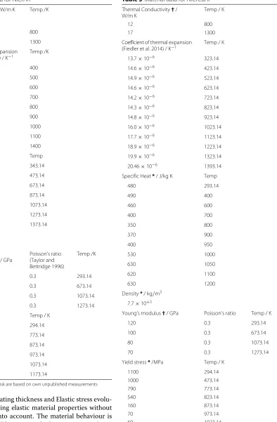
Material data
The material data used in the simuations are given in Tables 1, 2 and 3. The coefficient of thermal expan-sion (CTE) is the integrated value relative to room temperature. Thermal conductivity and Young’s modu-lus of NiCuCrAl have not been determined so far; in the simulations they have been assumed to be identi-cal to those of the NiCrAlY bond coat. Simulations in
Table 1Material data for the copper alloy CuCr1Zr
Thermal Conductivity / W/m K (Kupferinstitut 2005)
Temp / K
320 293.14
315 373.14
324 473.14
333 573.14
336 673.14
Coefficient of thermal expansion
(Dies 1967; Kupferinstitut 2005) / K−1 Temp / K
16.3×10⁻⁶ 373.14
17.0×10⁻⁶ 473.14
17.6×10⁻⁶ 573.14
18.3×10⁻⁶ 873.14
19.0×10⁻⁶ 973.14
19.8×10⁻⁶ 1173.14
20.9×10⁻⁶ 1356.14
Specific Heat (Kupferinstitut 2005) / J/kg K
Temp
370 293.14
450 373.14
480 473.14
500 573.14
500 673.14
Density (Kupferinstitut 2005) / kg/m3
8.91×10³
Young’s modulus (Kupferinstitut 2005) / GPa
Poisson’s ratio (Fassin 2015)
Temp / K
120 0.30 293.14
87 0.31 873.14
Yield stress (Baukloh et al. 1976; Kupferinstitut 2005; Zinkle and Fabritsiev 1994) / MPa
Temp / K
380 293
250 573
200 723
150 873
Table 2Material data for NiCrAlY
Thermal Conductivity / W/m K (Altun et al. 2008;
Pawlowski 2008)
Temp /K
12 800
17 1300
Coefficient of thermal expansion (Taylor and Walsh 2004) / K−1
Temp /K
13.0×10⁻⁶ 400
12.9×10⁻⁶ 500
13.1×10⁻⁶ 600
13.4×10⁻⁶ 700
13.7×10⁻⁶ 800
14.0×10⁻⁶ 900
14.3×10⁻⁶ 1000
15.6×10⁻⁶ 1100
19.0×10⁻⁶ 1400
Specific Heat*/ J/kg K Temp
460 343.14
410 473.14
330 673.14
230 873.14
400 1073.14
1440 1273.14
1370 1373.14
Density / kg/m3
6.9×10³
Young’s modulus
(Margadant et al. 2006) / GPa
Poisson’s ratio (Taylor and Bettridge 1996)
Temp /K
120 0.3 293.14
100 0.3 673.14
80 0.3 1073.14
70 0.3 1273.14
Yield stress*/MPa Temp / K
1200 294.14
1200 773.14
900 873.14
380 973.14
100 1073.14
60 1173.14
Data labelled with an asterisk are based on own unpublished measurements
Section Overall coating thickness and Elastic stress evolu-tion were done using elastic material properties without taking plasticity into account. The material behaviour is actually dominated by creep at high temperatures; how-ever, since the main effect of creep is to cause stress relaxation at high temperatures (so that thermal stresses
Table 3Material data for NiCrCuAl
Thermal Conductivity†/ W/m K
Temp / K
12 800
17 1300
Coefficient of thermal expansion
(Fiedler et al. 2014) / K−1 Temp / K
13.7×10⁻⁶ 323.14
14.6×10⁻⁶ 423.14
14.9×10⁻⁶ 523.14
14.6×10⁻⁶ 623.14
14.2×10⁻⁶ 723.14
14.3×10⁻⁶ 823.14
14.8×10⁻⁶ 923.14
16.0×10⁻⁶ 1023.14
17.7×10⁻⁶ 1123.14
18.9×10⁻⁶ 1223.14
19.9×10⁻⁶ 1323.14
20.46×10⁻⁶ 1393.14
Specific Heat*/ J/kg K Temp
480 293.14
490 400
460 600
400 700
350 800
370 900
400 950
530 1000
630 1050
620 1100
630 1200
Density*/ kg/m3
7.7×10+3
Young’s modulus†/ GPa Poisson’s ratio Temp / K
120 0.3 293.14
100 0.3 673.14
80 0.3 1073.14
70 0.3 1273.14
Yield stress*/MPa Temp / K
1100 294.14
1000 473.14
790 773.14
540 823.14
160 873.14
70 973.14
60 1073.14
develop on cooling), using plastic behaviour instead can be expected to lead to similar results. The temperature-dependent yield stress has been measured in compression tests of free-standing coatings for temperatures up to 800 ◦C for NiCuCrAl and up to 900 ◦C for NiCrAlY; values above that are estimates. Since large stresses evolve during cooling, the exact value of the yield stress at high temperatures does not strongly affect the final stresses in the coating as long as it is sufficiently small.
Thermal boundary conditions
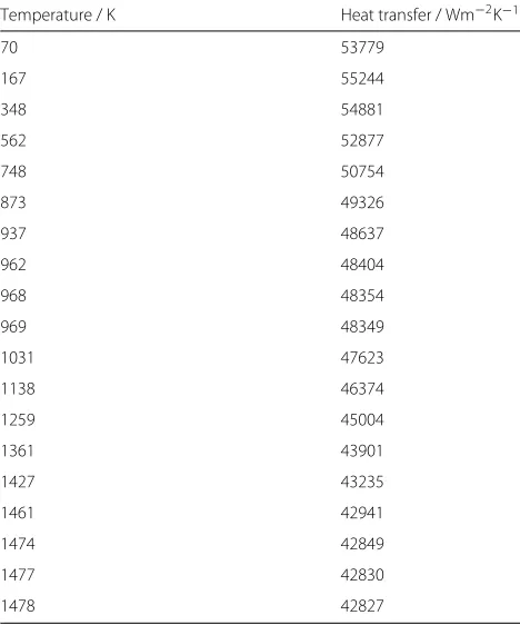
The temperature in the hydrogen cooling channel was assumed to be 70 K. This temperature was also cho-sen as the initial temperature of the model. A film cooling condition with a heat transfer coefficient of 145 kWm−2K−1was assumed at this side. On the hot side with gas temperature of 3410 K, a surface-temperature dependent film condition was assumed. Due to this film condition, the surface temperature of wall is considerably lower than the hot gas temperature, since it is deter-mined by the heat flux and the equation q˙ = αT, whereq˙is the heat flux per unit area,αthe heat transfer coefficient and T the temperature difference between hot gas and surface temperature (Bürgel et al. 2011). Values for the heat transfer coefficient are listed in Table 4. All data for the thermal boundary conditions were taken from a coupled FSI-model of the rocket engine (Kowollik 2015).
For a full cycle, heating was switched on for one second to ensure stationary conditions (a stationary state is reached after about 0.2 s, see Fig. 4 below), and then switched off again for 1 second so that the whole structure cooled down again to 70 K. No radiative heat transfer at the hot side was assumed.
Vertical crack model
Large tensile stresses and (cyclic) plastic strains in the
x2- and x3-direction develop in the model with plas-ticity after cooling. These stresses and strains can be expected to cause cracks perpendicular to the surface of the coating (x1-direction in Fig. 1). These cracks are called “vertical cracks” , in the following. (Similar cracks, usu-ally called “segmentation cracks” , are frequently observed in ceramic TBCs (Seiler et al. 2013). These cracks are caused during first heating to service temperature by the mismatch in thermal expansion. Since this is a different mechanism from the one discussed here, the term “seg-mentation crack” is not used in this paper). To study this possibility, the model was extended to allow debonding of the nodes in the top and bond coat of the system after cooling down. Nodes were debonded using a time-controlled debonding criterion, and the total energy of the model was calculated during the debonding process. This allows to calculate the energy release rate and thus to
Table 4Temperature-dependent heat transfer coefficient at the hot side of the copper liner (Kowollik 2015)
Temperature / K Heat transfer / Wm−2K−1
70 53779
167 55244
348 54881
562 52877
748 50754
873 49326
937 48637
962 48404
968 48354
969 48349
1031 47623
1138 46374
1259 45004
1361 43901
1427 43235
1461 42941
1474 42849
1477 42830
1478 42827
estimate whether vertical cracks might propagate to the copper substrate.
Results and discussion Overall coating thickness
In a first study, the total coating thickness was varied between 0μm and 120μm, using the same thickness for bond coat and top coat (since the thermal conductivity of both materials is assumed to be the same, varying the relative thickness of the two coatings does not affect the temperature profile). Figure 2 shows the maximum temperature at the surface of the structure and in the copper substrate as a function of overall coating thick-ness. As expected, the surface temperature increases with increasing thickness due to a reduced heat flux (Bürgel et al. 2011), whereas the temperature of the copper sub-strate decreases significantly. If we assume a maximum service temperature of 1150◦C for the top coat, a coating thickness of 90μm can be chosen. At this thickness, the maximum temperature of the copper substrate reduces by 200 K from 1122 K to 922 K. This reduction can be expected to strongly reduce creep in the material. In the subsequent studies discussed in the next sections, the total coating thickness was therefore fixed at 90μm.
Fig. 2Surface temperature and maximum copper temperature for different total coating thicknesses
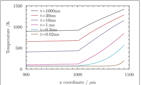
in the coating, whereas the copper substrate lags behind due to the thermal insulation effect. A strong temper-ature gradient evolves in the thermal barrier coating. (The small deviation from a linear function at the bond coat/copper interface is due to the sinusoidal shape of the interface).
Figure 4 shows the temperature history for points located in the middle of each of the three materials for the case of 45μm bond coat and 45μm top coat. A sta-tionary state is reached after less than 0.2 s. The figure also shows the temperature difference between the copper substrate and the top coat. Due to its lower thermal con-ductivity and the vicinity to the heat source, the top coat heats up considerably faster than the substrate, leading to a maximum in the temperature difference. This will become important in section Plastic stress evolution.
Elastic stress evolution
In gas turbine applications, failure of thermal barrier coat-ings is driven by microcracks developing at the interface
Fig. 3Temperature evolution in the upper 100μm of the copper substrate and the coating on the lower edge of the model for a coating thickness of 90μm
between the top coat and the bond coat, where a ther-mally grown oxide layer forms. These cracks are due to growth stresses and thermal mismatch stresses at the interface in the direction vertical to the interface (x1-direction in the geometry of Fig. 1). In a rocket engine, the high temperature exposure time is too short for a critical oxide layer to form. Furthermore, since the dif-ference in the CTE is smaller in the coatings considered here, the thermal mismatch stresses are actually rather moderate. Figure 5 shows the stresses calculated in the purely elastic model at the end of hold time. Maximum tensile stresses are below 140 MPa. If all stresses would relax during hot time, cooling stresses of similar magni-tude and opposite sign can be expected after cooling (see also Fig. 10 below).
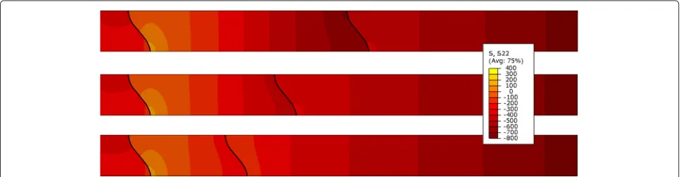
In addition to these stresses, the in-plane stresses may be important because they contribute to bending and buckling of the coating. Figure 6 shows the elastic stress
Fig. 5Elastic stresses in 11-direction at the end of the heating step
in 22-direction for three different coating thicknesses (bc/tbc) 45μm/45μm, 30μm/60μm, and 20μm/70 μm. As can be seen, large compressive stresses develop at the interface for equal thicknesses of tbc and bond coat; these stresses are reduced and the stress profile becomes more homogeneous if the bond coat thickness is reduced. Note that after stress relaxation, the coating will be under tension in the in-plane direction when cooled down.
Plastic stress evolution
In the previous section, thermal stresses generated dur-ing heatdur-ing have been calculated. These stresses can also be used to estimate stresses after cooling under the sim-plifying assumption that all stresses relax during hot time. Although this assumption is plausible in the coating where temperatures are large, stresses in the copper substrate will not relax fully. This has a strong effect on the in-plane stresses in the coating.
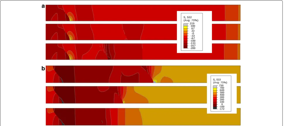
To study the effect of plastic deformation in greater detail, temperature-dependent plasticity is assumed in the materials. Figure 7 shows the 22-stress at the end of the heating time and after cooling down. On first sight, it may be surprising to see that tensile stresses develop at the top of the coating where the temperature is largest and where therefore maximum thermal expansion can be expected. The reason for this is the transient maximum in the tem-perature difference between coating and substrate shown in Fig. 4. This leads to a large difference in thermal strains during the initial heating phase, causing plastic flow in the top of the coating. Upon further heating, the temperature
difference decreases so that tensile stresses can develop. (It should be noted that, since the transient maximum of the temperature difference occurs only for a very short time, hardening due to rate-dependent plasticity might reduce this effect. This has not been taken into account here because material data are not available and because the details of the ignition of the rocket engine are not represented in the heat flux as defined in Table 4).
After cooling to room temperature, large thermal strains develop in the coating leading to large in-plane tensile stresses in the coating, see Fig. 7b. The possibility of ver-tical cracks driven by these stresses will be discussed in section Vertical cracks.
Figure 8 shows a plot of the elastic strain in the coat-ing versus temperature. If all materials are elastic, the strain history is completely reversible so that no changes occur when several cycles are performed. For the case with plasticity, the plastic deformation during heating in the first cycle causes a decrease of the elastic strain as explained above, so that the first cycle differs from subse-quent cycles. After the first cycle (4 cycles are shown in the figure), no further change occurs because there is no further plastic deformation.
CTE influence
From the results shown in the previous sections, it is obvious that the stress in the coating is governed by the interplay of the temperature gradient and the CTE mis-match. One possibility to reduce these stresses would be to tailor the CTE of the coating material so that the
Fig. 7Stresses in 22-direction in the coating at the end of heating and cooling with plasticity for three different thicknesses of bond coat and tbc.
aEnd of heating time.bEnd of cooling time
thermal strain in the coating is the same as the strain prescribed by the copper substrate.
In the elastic case, the calculated temperature field (Fig. 3) can be used to calculate the thermal strains at each position. Based on this, the CTE needed to ensure a stress-free coating at the end of the heating period can be calculated as a function of temperature (Fig. 3). This is shown in Fig. 9. As expected, the CTE should reduce with temperature to avoid compressive stresses in the coating close to the surface. Since the CTE in standard materials increases with temperature, this temperature dependence of the CTE could only be achieved by varying the material, e. g. by applying a graded coating. However, the absolute
Fig. 8Evolution of temperature vs. elastic strain with and without plasticity for a material point at the coating’s surface for a coating thickness of 45μm/45μm. For the elastic case, there is no change in the strains if several cycles are performed; for the plastic case, the first cycle differs from subsequent cycles, but no changes occur after the second cycle since there is no further plastic deformation
value of the CTE at the highest temperature is unrealisti-cally small for a metallic coating (Touloukian et al. 1975) so that it seems unrealistic to create a stress-free coat-ing in this manner. Furthermore, plastic deformation has a considerable effect on the developing strains which also affects the role of the CTE. In the purely elastic case, the strain at the surface at the end of hot time is approximately 0.75 % (Fig. 8); the calculated CTE for a stress-free state at the highest temperature in Fig. 9 is based on this value. If plastic deformation is taken into account, the strain at the end of hot time is very small, so the ideal CTE should be based on the residual strain after cooling. This value is approximately 0.3 % and is thus considerably smaller so that the desired reduction in the CTE should be correspondingly smaller.
Fig. 10Stress field for reduced CTE in the coating at the end of the cooling step.aStress in 11-direction.bStress in 22-direction
To further evaluate the effect of changing the CTE, simulations with a reduced CTE (80 % and 60 % of the standard value from Table 2) in the top coat material have been performed, using the model with plasticity. The resulting stress fields are shown in Fig. 10. The in-plane stresses after cooling in the coating reduce to less than 100 MPa for the case of a CTE reduction to 80 %. If the CTE is reduced further, the top-coat material is actually in in-plane compression. From this, it seems that reducing the CTE might be a possible way of reducing the danger of vertical cracks.
However, since the CTE of the bond coat has not been changed, the interfacial 11-stresses increase so that the reduction of the in-plane stresses is accompanied by an increase of the interfacial stresses. The maximum ten-sile stress after cooling increases from about 210 MPa to more than 380 MPa, so that the danger of interfacial cracks increases. Using a graded coating, this effect could be reduced.
Overall, it seems that choosing a top coat material with a smaller CTE than NiCrAlY (possibly together with a graded coating structure) might be beneficial to reduce the stresses.
Vertical cracks
To study the possibility of vertical cracks forming in the coating after cooling, a node release technique as
described in section Vertical crack model has been used for the two coating thicknesses 45 μm/45 μm and 20 μm/70 μm. Figure 11 shows the elastically stored energyW per unit thickness in the model as a function of the crack lengtha. A linear fit was used in the top coat and bond coat regime to calculate the energy release rate
G = dW/da. The calculated energy release rate in the
Fig. 11Stored energy per unit thickness for vertical crack propagation with coating thickness 45μm/45μm and 20μm/70μm. The straight lines are fit lines used in the top coat and bond coat region, resp. The inset figures show a zoom of the energy change near the
top coat isGtop45/45 = 8.96 J/m2andGtop20/70 = 8.84 J/m2 for the two different geometries. In the bond coat, the values are considerably smaller:Gbc45/45 = 0.48 J/m2and
Gbc20/70=0.43 J/m2. Close to the interface (see the insets in Fig. 11), the energy stays constant during crack propaga-tion because the stress state is compressive. In the region directly adjacent to the interface, the tensile stresses in the copper cause an increase of the energy release.
The lower value of the energy release rate in the bond coat is not due to its larger CTE, but rather to its lower yield stress. At temperatures between 1100 and 900 K during the cooling process, where the tempera-ture difference to the substrate is larger, the bond coat yields plastically and thus strongly reduces the thermal strains.
Note that the mirror symmetry employed in the model means that the distance between two vertical cracks is twice the thickness of the model, i. e. 17 μm. Since the stress field is almost homogeneous in the coating (at some distance from the interfaces), the stored energy is pro-portional to the thickness of the model. This can be used to estimate the distance between vertical cracks. If the critical energy release rate in the top coat is Gtopc , the distance between vertical cracks should be of the order of 17μm·Gtopc /Gtopmeasured.
The critical energy release rate at the interface between a plasma-sprayed NiCrAlY bond coat and a nickel sub-strate is of the order of 150 J/m2 (Clyne and Gill 1996). Vertical cracks inside the coating can be expected to have a larger energy release rate. If we assume a value of 250 J/m2, a typical distance between vertical cracks will be approximately 500μm.
These cracks will not propagate into the bond coat because the energy release rate is strongly reduced there due to plastic deformation on cooling that reduces ther-mal strains. It is of course still possible that some of the cracks propagate into the bond coat, but the distance of vertical cracks in the bond coat can be expected to be larger. Due to the compressive stress in the bond coat close to the copper interface, these cracks will probably not propagate into the substrate.
The energy release rate in the top and bond coat does not depend strongly on the thickness of the two coating components. Therefore, although the stress calculation itself seems to favour a thinner bond coat, this will lead to deeper vertical cracks. Since the energy release rate in the top part of the copper substrate is larger than in the bond coat, a sufficient thickness of the bond coat is probably helpful to ensure that no vertical cracks reach in the substrate.
Conclusions
In this paper, a finite element model of a metallic thermal barrier coating system in a rocket engine has been studied.
The following conclusions and design guidelines can be drawn:
• In a NiCrAlY/NiCuCrAl-TBC, a reasonable coating thickness is 90μm. This reduces the substrate temperature by approximately 200 K.
• Interface stresses in thickness direction are rather small both at the substrate/bc and at the bc/tbc interface, so that crack propagation at the interface is expected to be less pronounced than in gas turbine applications.
• In-plane stresses can become large in the system. If stresses relax at high temperatures, large tensile stresses can be expected after cooling.
• The thickness ratio bc/tbc strongly influences the stress field. A thin bond coat leads to a smooth stress field with no local maxima, however, it may also lead to deeper vertical cracks.
• Plasticity in the coating changes the stress field considerably and may even lead to tensile stresses at the hot time due to a transient maximum in the temperature difference between coating and substrate. Thus it is important to evaluate the temperature history during the ignition of the engine.
• Reducing the CTE of the top coat will reduce in-plane stresses, However, if the value is too small, the increase in the interface stresses in thickness direction may offset the advantages of a reduced CTE. Nevertheless, choosing a top coat material with a smaller CTE, possibly together with applying a graded coating, may be a promising way of optimising the coating.
• Due to the large tensile stresses in the top coat after cooling down, a vertical crack network can be expected to form in the top coat. The critical energy release rate for propagation in the bond coat is considerably smaller so that most vertical cracks can be expected to stop upon reaching the bond coat.
To optimize the ratio of the top coat/bond coat thickness, the following effects need to be considered: (i) the transient temperature maximum, (ii) the reduction of in-plane stress gradients when the bond coat is thin, (iii) the propagation of vertical cracks through the bc into the substrate. To evaluate these effects in detail, experiments under realistic conditions are needed to understand the dominating failure mechanisms.
Competing interests
The authors declare that they have no competing interests.
Authors’ contributions
Acknowledgements
Financial support by the German Research Foundation (Deutsche Forschungsgemeinschaft/DFG) in the framework of the
Sonderforschungsbereich Transregio 40, Teilprojekt D2 is gratefully acknowledged. Data on the heat transfer were kindly provided by Matthias Haupt and Daniel Kowollik, Technische Universität Braunschweig.
Received: 22 June 2015 Accepted: 26 August 2015
References
Altun O, Boke YE, Kalemtas A (2008) Problems for determining the thermal conductivity of TBCs by laser-flash method. J Achiev Mater Manuf Eng 30:115–120
Bürgel R, Maier HJ, Niendorf T (2011) Handbuch Hochtemperatur-Werkstofftechnik. Vieweg, Wiesbaden
Baukloh A, Drehfahl K, Heubener U, Rühle M (1976) Zeitstandsuntersuchungen an niedrig- und unlegierten Kupferwerkstoffen. Metall 30(1):19–28 Clyne TW, Gill SC (1996) Residual stresses in thermal spray coatings and their
effect on interfacial adhesion: A review of recent work. J Therm Spray Tech 5(4):401–418. doi:10.1007/BF02645271
Dies K (1967) Kupfer und Kupferlegierungen in der Technik. Springer, Heidelberg
Fassin M (2015) Poissons Ratio of CuCr1Zr. Institute of Applied Mechanics RWTH Aachen University, private communication
Fassin M, Tini V, Vladimirov I, Reese S (2014) Life prediction of a rocket combustion chamber wall by a viscoplastic damage model. Proc Appl Math Mech 14:149–150
Fiedler T, Fedorova T, Rösler J, Bäker M (2014) Design of a nickel-based bond-coat alloy for thermal barrier coatings on copper substrates. Metals 4:503–518
Freborg AM, Ferguson BL, Petrus GJ, Brindley WJ (1998) Modeling oxidation induced stresses in thermal barrier coatings. Mater Sci Eng A245:182–190. Chap. 207429
Greuel D, Suslov D, Haidn O, Fritscher K (2002) Thermal barrier coatings for cryogenic rocket engines. AIAA J 1:4145
Kowollik DSC, Horst P, Haupt MC (2013) Fluid-structure interaction analysis applied to ther barrier coated cooled rocket thrust chamber with subsequent local investigation of delamination phenomena. Prog Propuls Phys 4:617–636
Kowollik D (2015) Private Communication
Kupferinstitut D (ed) (2005) Kupferdatenblatt CuCr1Zr. Deutsches Kupferinstitut, (German Copper institute. https://www.kupferinstitut.de/ fileadmin/user_upload/kupferinstitut.de/de/Documents/Shop/Verlag/ Downloads/Werkstoffe/Datenblaetter/Niedriglegierte/CuCr1Zr.pdf, see also https://www.kupferinstitut.de/de/persoenlicheberatung/shop-verlagdownloads/downloads/werkstoffe/werkstoff-datenblaetter.html Margadant N, Neuenschwander J, Stauss S, Kaps H, Kulkarni A, Matejicek J,
Rössler G (2006) Impact of probing volume from different mechanical measurement methods on elastic properties of ththermal sprayed Ni-based coatings on a mesoscopic scale. Surf Coat Technol 200:2805–2820
Ogbuji L (2005) A table-top technique for assessing the blanching resistance of cu alloys. Oxid Met 63(5–6):383–399
Padture NP, Gell M, Jordan EH (2002) Thermal barrier coatings for gas-turbine engine applications. Science 296(5566):280–284
Pawlowski L (2008) Science and Engineering of Thermal Spray Coatings. John Wiley & Sons Ltd., Hoboken, NJ
Popp M, Schmidt G (1996) Rocket Engine Combustion Chamber Design Concepts for Enhanced Life. In: AIAA, ASME, SAE and ASEE Joint Propulsion Conference and Exhibit No. 32, Lake Buena Vista
Quentmeyer RJ (1977) Experimental Fatigue Life Investigation of Cylindrical Thrust Chambers. In: AIAA/SAE Propulsion Conference No. 13. American lnstilute of Aeronautics and Astronautics, 1290 Avenuo of the Americas, New York, N.Y. 10019
Quentmeyer, RJ (1988) Thrust chamber thermal barrier coating techniques. NASA Rep Tech Memorandum NASA TM-100933
Raj SV, Ghosn LJ, Robinson C, Humphrey D (2007) High heat flux exposures of coated GRCop-84 substrates. Mater Sci Eng A 457:300–312
Schloesser J, Bäker M, Rösler J (2011) Laser cycling and thermal cycling exposure of thermal barrier coatings on copper substrates. Surf Coat Technol 206:1605–1608
Schloesser J (2014) Mechanische Integrität von Wärmedämmschichten für den Einsatz in Raketenbrennkammern. PhD thesis, Technische Universität Braunschweig, Der Andere Verlag, Uelvesbüll
Seiler P, Bäker M, Rösler J (2013) Multi-scale failure mechanisms of thermal barrier coating systems. Comput Mater Sci 80:27–34
Taylor TA, Walsh PN (2004) Thermal Expansion of MCrAlY Alloys. Surf Coat Technol 177–178:24–31
Taylor TA, Bettridge DF (1996) Development of Al Alloy and
Dispersion-Strengthened MCrAlY Coatings. Surf Coat Technol 86–87:9–14 Touloukian YS, Kirby RK, RE Taylor, PD Desai (1975) Thermophysical Properties
of Matter 12 - Thermal Expansion - Metallic Elements and Alloys. IFI/Plenum, New York - Washington
Zinkle SJ, Fabritsiev SA (1994) Copper alloys for high heat flux structure applications. At Plasma Mater Interact Data for Fusion 5:163–191
Submit your manuscript to a
journal and benefi t from:
7 Convenient online submission
7 Rigorous peer review
7 Immediate publication on acceptance
7 Open access: articles freely available online 7 High visibility within the fi eld
7 Retaining the copyright to your article