1
Evaluation of Fuel Diversity in Solid Oxide Fuel Cell System
Amirpiran Amiri+,*,1 , Shi Tang+,2, Robert Steinberger-Wilckens3, Moses O. Tadé4
1European Bioenergy Research Institute (EBRI), School of Engineering and Applied Science, Aston University, Birmingham, B4 7ET, United Kingdom
2Hubei Key Laboratory of Mechanical Transmission and Manufacturing Engineering, Wuhan University of Science and Technology, Wuhan, 430081, PRC
3School of Chemical Engineering, University of Birmingham, Edgbaston, Birmingham, B15 2 TT, UK
4Department of Chemical Engineering, Curtin University, Kent Street, Bentley, WA 6102, Australia
+Co-first Authors
*Corresponding Author: [email protected]
Abstract
Operability of Solid Oxide Fuel Cell (SOFC) on numerous fuels has been widely counted as a leading advantage in literature. In a designed system, however, switching from a fuel to another is not practically a straightforward task as this causes several system performance issues in both dynamic and steady-state modes. In order to demonstrate the system fuel diversity capabilities, these consequences must be well-evaluated by quantifying the characteristic measures for numerous fuel cases and also potential combinations. From this viewpoint, the numerical predictive models play a critical role. This paper aims to investigate the performance of a SOFC system fed by various fuels using a demonstrated system level model. Process configuration and streams results of a real-life SOFC system rig published in literature are used to validate the model. The presented model is capable not only of capturing the system performance measures but also the SOFC internal variable distributions, allowing the multiscale study of fuel switching scenarios. The fuel change impacts on the system are simulated by considering various fuel sources, i.e., natural gas, biogas, and syngas. Moreover, applications of simulated fuel mixtures are assessed. The modelling results show significant concerns about fuel switching in a system in terms of variation of efficiencies, stack internal temperature and current density homogeneity, and environmental issues. Moreover, the results reveal opportunities for multi-fuel design to address the operation and application requirements such as optimisation of the anode off-gas recycling rate and the thermal-to-electrical ratio as well as the system specific greenhouse gases, i.e., g-COx/Wh release.
2
Introduction
Fuel cells have increasingly received attentions as a promising green technology for future high-efficiency energy conversion. SOFCs, in particular, offer very interesting features such as operability on a wide spectrum of fuels owing to their high temperature operation [1-5]. Natural gas (NG), biogas (BG), syngas (SG) derived from biomass/coal gasification, and hydrogen are just a few examples of potential SOFC fuels. Renewable hydrogen sources, in particular, have increasingly received attention in recent years [6-8]. The integration of renewable hydrogen production process and fuel cell system is a practical solution for the issues relevant to hydrogen storage and transportation. The fuel reformation process can be carried out either internally or externally under technical and operational considerations associated to each. Moreover, the fuel reformation reaction pathways might be through various thermodynamically feasible mechanisms such as steam reforming, water-gas-shift reaction, partial oxidation, etc [9-10]. In spite of all promising opportunities mentioned, switching between numerous potential fuels and/or fuel reformation strategies is highly challenging due to the subsequent impacts on the system performance and control [11-12]. Analysis of the system behaviour operating on such wide fuel and fuel processing alternatives requires tens of scenarios to be examined [13]. In this view, without underestimating the crucial importance of experimental studies, the numerical models are more often preferred to study the possible scenarios particularly where both experimental and theoretical investigations are the alternative options.
3
Accordingly, the research outcomes based on an isolated single cell might not be directly generalised to the cells embedded in a multi-cell stack. Similarly, an isolated fuel cell stack unit may behave differently compared to when it is integrated with BoP units working interactively. Although the single scale focused model offers significant advantages, e.g., simpler equation sets and faster computation, a practical fuel cell system model must ideally capture the main spatio-temporal and the interactive scales involved through a computationally effective multiscale modelling framework. This is, particularly, of critical importance in assessing various fuels and fuel reformation pathways where the fuel pre- and post-processing component impacts on the fuel cell stack and vice versa must not be compromised.
Fuel diversity assessment requires a multiscale system level model. In a previous study [15] the emphasis was placed on the stack-BoP interactions as well as the stacking related matters, such as manifold malfunction, to capture the stack internal distribution profiles and gradients. Even though a parametric analysis at system level was presented, estimation of flowsheet streams data and interaction of BoP components were out of scope. This is a lack as the process design and process optimisation, at both basic and detailed design stages, largely rely on the flowsheet mass and energy balance data. This paper aims to cover the mentioned modelling gap and then analyse the fuel diversity relevant concerns at system level with special attention to the stack internal profiles by using a detailed stack model embedded in the BoP. To meet these a SOFC system test rig presented in [16] was simulated first for model upgrading and validation specifically in predicting the system level performance. Subsequently, the impact of fuel source variation on the system and SOFC stack performances will be estimated and discussed.
Modelling outline and model validation
4
between the SOFC stack and other BoP components is bidirectional by recycling the exhaust gases from stack outlet to the system upstream forming the recirculation loops in the process flowsheet. The simulation and verification of SOFC flowsheet data is conducted in this work to prove the model fidelity and reliability.
System Performance Measures
In order to capture the influence of the fuel variation on the stack and system performance, several performance indicators are taken into account. Variables including the system combined efficiency (
System
η ), stack current density (i), stack average temperature (TStack ), temperature differences
between the stack input and output (∆T), and system exhaust temperature (TExhaust) are evaluated.
System energy input rate ( System in
P ) via chemical fuel is considered to be constant as 90 W, regardless of the fuel type. Accordingly, given LHV values for each fuel, the corresponding fuels molar flowrates (Ffuel) are estimated by using Equation 1;
F inSystem
fuel
fuel
P LHV
= (1)
Furthermore, the stack electrical efficiency is calculated as (Equation 2);
net
el System
in
P P
η = (2)
The net system power,Pnet,is estimated based on the electric power generation and consumption within the system (Equation 3):
( )
. Stack Blowernet
P = V I −P (3)
where
𝑃𝑃𝐵𝐵𝐵𝐵𝐵𝐵𝐵𝐵𝐵𝐵𝐵𝐵 =𝐹𝐹
𝛼𝛼𝐶𝐶𝑝𝑝𝑇𝑇0�
�𝑝𝑝𝑜𝑜𝑜𝑜𝑜𝑜𝑝𝑝0 �
𝑘𝑘−1
𝑘𝑘 −1
𝜂𝜂𝑖𝑖𝑖𝑖𝑖𝑖𝑖𝑖𝐵𝐵𝐵𝐵𝑜𝑜𝐵𝐵𝑖𝑖𝐵𝐵 � (4)
The available thermal energy in the system (Eth) is estimated as the system exhaust gas enthalpy that
5 th th System in E P β
η = (5)
Total (combined) system efficiency is calculated as:
System
el th
η =η +η (6)
For the stack distributed variables, a deviation factor is calculated based on the Equation 7: .
(%) j j 100
j j
n M M
D
M −
=
∑
×∑
(7)where M is the stack variable (= i, T, ∆T), n stands for number of fuels (= 6), and j is fuel type (j = NG, BG, SG, SF#1, SF#2, SF#3)
Experimental rig simulation
A SOFC system test rig with external fuel pre-processing unit has been demonstrated by Powell et al. [16]. The presented process consists of major SOFC system components including the steam reformer, recuperators, and blowers for anode and cathode gas streams, exhaust condenser, and mass flow controllers all integrated with a multilayer SOFC stack. The demonstrated system attained net power output of 1650 – 2150 W with a maximum net electrical efficiency of 0.60 calculated based on LHV. The test rig had no afterburner. Sulphur free CH4 (purity > 99.9%) was utilised as the fuel.
The external fuel reformer, however, was fed with a mixture of fresh fuel mixed with a part of anode exhaust gases recycled at a rate of 85%. The recycle rate is defined as the percentage of anode outlet flow that is used in the reformer rather than being vented. The reformate properties are a strong function of reformer operating conditions including reformer temperature, pressure, and residence time, and the recycle ratio as well as the composition of fresh feed, etc. Given the operating conditions in [16], the reformate fed into the SOFC stack mainly consisted of CO, CO2, H2, H2O,
and possibly a very small portion of unreacted CH4. Therefore, internal reforming can reasonably
6
account, the lab scale process, Figure 1A presented in [16] was simulated as can be seen in Figure 1B.
The system presented in [16] possesses an external fuel reformer and operates with a co-flow pattern for air and fuel inside cells. We used the same reforming and flow specifications to be able to compare the results for simulation validation. Since a co-flow pattern for the fuel and air flows in the cell channels was simulated, changes in y direction shown in Figure 1 were negligible. Moreover, the heat transfer between the cells/layers inside the stack and also between stack and environment was neglected. The former was because of the minor impact of cell-to-cell thermal impact within the four cell short stack [15, 21]. The latter assumption was justifiable for a well-insulated SOFC stack operating adiabatically in the system. Moreover, an even distribution of fuel and air between layers in the stack was assumed. Taking all of these assumptions into account, variations in stacking direction, z, could be ignored and therefore the profiles were only captured in one dimension along the cell length, x. The recycle ratio used in the simulations was 0.85 to be consistent with the practical test rig operating conditions [16].
As can be seen in Table 1 the simulated results were in reasonable agreement with the experimental data. The calculated electrical efficiency for the methane-fed system was about 62% which was well consistent with the experimental data in [16]. Note that no thermal efficiency was considered in the mentioned work hence the overall efficiency was estimated based on the electrical efficiency only. There is discrepancy between the model and experimental results for Stream 15, and hence 16. The reason is that while the air/fuel ration was ~13.5 in the test rig operation, it was adjusted at ~21 in the simulation to reasonably fit the temperatures. Therefore, the oxygen utilisation achieved through the model was lower than real one as is reflected in Stream 15/16. Moreover, the inconsistency between the model-based predicted and experimentally measured data for Stream 11 is because of data reporting basis, i.e., dry and wet basis. Since cooling process for Stream 10, reducing temperature from 200 °C to 25 °C using a small size condenser is technically challenging, it seems that this has not been successfully achieved in the experiments [16], passing water mainly into Stream 11 rather than water drain steam (H2O stream in Figure 1A). This, however, was not the case
in the simulation where it is thermodynamically possible to remove water from tail gas at 25 °C leaving dry Stream 11.
Process analysis results and discussion
7
demands, and also heat for external uses, such as hot water preparation in residential applications. In this aspect, the afterburner is a very important component of the SOFC system to be simulated for a fuel assessment study. Since the process presented in [16] did not include the off-gas burner, the process flowsheet was modified, as shown in Figure 2, to include the burner in the thermal efficiency estimation, enabling a more comprehensive process analysis.
Impact of fuel source
The impact of fuel change on the system performance characteristics was analysed based on the model and parameters presented in Figure 2 and Table 2, respectively. There are further parameters that are not used in this work directly, but are used in the simulator equations and programming demonstrated in [17].Three widely accepted fuels for SOFC, including NG, BG and coal SG, were used in the simulation. Moreover, three so-called “simulated fuel (SF)” mixtures generated by mixing of NG and SG gases were taken into account. In order to parametrically explore the SF features, the NG and SG fractions in SFs compositions were assumed as there is no specific standard composition available in the literature. The SF mixture properties were estimated by Aspen Plus using the inbuilt mixing rules.Fuel specifications are presented in Table 3.The flowsheet stream results relevant to each fuel are presented in the Appendix.
The results presented in Table 4 reveal that the fuel type/source considerably influences the SOFC stack and system performance. With respect to the individual efficiency terms, seen in Equation 6, application of NG fuel results in a maximised electrical efficiency and minimised thermal efficiency compared to other fuels. Taking the endothermic NG reformation reaction into account, the higher electrical efficiency stems from the recycling of heat into the reformer and thus conversion of (waste) heat into chemical (fuel) energy that can then be converted into electricity. From this perspective, we would expect lower electrical efficiencies with higher hydrogen fuel content as heat recovery opportunity via fuel conversion is lesser. The NG-fed system overall efficiency is maximum compared against other fuels. In contrast, a system that operates on SG offers the lowest electric and highest thermal efficiencies because this is the only gas without CH4 content and thus
does not benefit from waste heat recycling in the reformer. These observations are relevant to H2
8
of view, a BG-fed system stands in the middle of the list having electrical and thermal efficiencies reasonably balanced. While stack feed dilution reduces the generated current and hence causes the electrical efficiency reduction in the stack, its thermal efficiency is improved compared to the NG-fed process.
Figure 3 captures current density and temperature profiles for the deployed fuels. Along the x-axis, current and temperature profile inhomogeneity are maximum and minimum for NG and SG fuels, respectively. Given equal stack inlet temperature for all fuels involved in this analysis, temperature growth due to the electrochemical reaction heat along the cell length varies considerably. The NG-fed cell shows the maximum temperature growth that can be explained based on the exothermic current generation reaction and hence the heat accumulation. Higher current comes at the cost of extreme temperature gradients that cause thermal stresses. All fuels offer average stack temperatures high enough to conduct the methane internal reforming process in case external reformation was not perfect. The temperature and current profile differences become more considerable towards the cell outlet. By switching the fuel from SG to NG, temperature and current density may vary up to 26 K, and 1400 A/m2, respectively, at the cell
outlet. This shows that the design of the cooling system must be chosen differently for individual fuels.
The more homogenous the reaction and temperature profiles, the better cell and stack performance will be in terms of lifetime. Therefore, internal gradients are among the key indicators that must be estimated to evaluate the impacts of fuels switching. For the comparison purpose the deviation factors – defined as the deviation from an overall average value that is achieved across the studied fuels – for stack variables fuelled by different fuels were calculated based on Equation 7 and presented in Figure 4. While positive deviations for current and temperature are desirable, as they show that the fuel change enhances the electrochemical reaction and hence the cell electric performance, the negative deviation for ∆T is more desirable as it indicates lower thermal inhomogeneity inside the stack. Since temperature profiles captured in this study are approximately linear, we use ∆TStack/Lcell and dT/dx as exchangeable alternatives in this paper.
9
SG as fuel, a minimum ∆T can be achieved at the price of a reduction in current generation. An anode outlet temperature reduction is observed that can be explained by a declining exothermic electrochemical reaction. However, this can be advantageous as heat can be recovered from unreacted fuel in the burner and result in higher thermal efficiency term as shown in Table 4. SOFC systems operated by using BG and simulated fuels behave between the extreme cases, i.e., a system fuelled by a mixture of NG and SG, offering substantial potential for fuel design to address internal homogeneities, in addition to the efficiency concerns presented in Table 4, through multivariable optimisation efforts.
Distributed voltage data for various fuels studied in this work are depicted in Figure 5. Note that all simulations are based on a constant operating voltage while local OCV and overpotentials are estimated using the local temperature and concentration conditions. As can be seen in Figure 5, application of NG as main fuel leads to the highest local OCV and overpotentials compared to the rest of fuels listed. In particular, the OCV profile for a stack fuelled by a reformate mixture from NG is considerably noticeable from the others. This result indicates the crucial importance of the reformate properties, and hence the fuel source, in stack voltage characteristics. The SG-fed system shows minimum local values of OCV and losses. While the cathode activation loss trends remain almost the same for all fuels, declining at the same rate along the cell length, the reduction rate of the anode activation loss is more considerable for NG compared to that of the other fuels. The difference between anode activation losses of various fuels becomes less at points close to the cell outlet.
Thermal-to-electrical ratio (TER)
10
System COx analysis
The COx released from the fuel cell system is also a critical measure in assessing the applicability of
various potentials fuels. While the overall specific COx release per unit power (g-COx/Wh), as the
most common indicator, is estimated, CO, and CO2 fractions are also calculated at two points of the
process, the stack anode outlet and the system exhaust. From the process design and analysis viewpoint, the chosen process points are logical bottlenecks to be checked. Indeed, stack outlet flow data help in designing appropriate strategies for the anode and cathode off-gas post-processing within the system itself, such as estimating the portion of stack exhaust gasses to be either burnt or recycled. Moreover, system overall emission evaluation and control can be undertaken by using the system exhaust composition information from the flowsheet.
As can be seen in Figure 7, the simulation results indicate that residual gases from NG and SG fuelled systems are, respectively, the cleanest and dirtiest outlets in terms of CO2 content. The CO share in
the system exhaust is negligible mainly because of almost complete conversion of CO to CO2 in the
burner. Moreover, this stream is significantly diluted by the added cathode off-gas inserted to the burner. However, this does not affect the associate g-COx/Wh for fuels. The simulation results show
about 250 g-COx/kWh for a system operated by using NG which is in agreement with technical
literature [25].
For all examined fuels, the stack exhaust consists of a considerable amount of CO and hence reveals the importance of internal water gas shift reaction and CO oxidation, both using CO as fuel. Nevertheless, a high rate of anode off-gas recycling may not be recommended in cases with high CO2/CO ratio, to minimise the carbon formation risk in the stack caused by a high CO2 partial
pressure. While the mentioned ratio is about 0.11 for NG, it is about 0.29 and 0.67 for BG and SG, respectively. This observation reveals the challenges relevant to anode off-gas recycling in a fuel changing scenario. As Figure 7 shows, the simulated fuels sound promising for handling a CO2/CO
ratio adjustment.
Conclusions
11
Evaluation of the fuel processing and fuel source alterations can require tens of scenarios to be tested. Numerical tools and particularly commercial process flowsheeting platforms that are capable to take stack details into account are critically required to minimise the cost and time of such numerous test series. Application of a user-defined SOFC stack in the Aspen Plus environment was demonstrated in this paper to assess the fuel change challenges and opportunities in a typical SOFC plant. The SOFC plant was simulated based on a real-life test set-up for validation purposes. The process flowsheet was modified to include an afterburner unit for fuel post-processing for meeting the heat generation target. It was shown that fuel variation may significantly affect the uniformity of stack internal profiles and system overall performance metrics. Moreover, the modelling observations give the insight for system-wide multi-objective optimisation opportunities through fuel selection and design. Results show that NG is a suitable fuel for a system that is mainly designed for electricity production applications while heat generation is of lower importance. On the other hand, BG could be suggested as promising fuel for balanced cogeneration of electric and thermal energies to meet the TER requirement in various applications. In contrast, a SOFC-based system fuelled by SG offers high thermal output at the cost of reduced electrical output compared to NG and BG-fed systems. It also moderates the thermal stresses inside the stack. Since all of the desirable specifications are not available in a single fuel, a multi-variable-multi-objective optimisation is needed. Fuel blending is an option to attain a specification of interest in a fuel mixture while its composition is designed/optimised.
Appendix
The system stream results for the process (Figure 2) fed by the studied fuels, i.e., NG, BG, SG, SF#1, SF#1 SF#1, are presented in Tables A1–A6, respectively
Acknowledgements
12
References:
[1] Yi Y, Rao AD, Brouwer J, Samuelsen GS. Fuel flexibility study of an integrated 25 kW SOFC reformer system . Journal of Power Sources. 2005;144:67-76.
[2] Yoon SP, Kim HJ, Park BT, Nam SW, Han J, Lim TH, Hong SA. Mixed-fuels fuel cell running on methane-air mixture. Journal of Fuel Cell Science & Technology. 2006;3:83-6.
[3] Douvartzides SL, Coutelieris FA, Demin AK, Tsiakaras PE. Fuel options for solid oxide
fuel cells: A thermodynamic analysis. AICHE Journal. 2010;49:248-57.
[4] Ni M. Modeling of SOFC running on partially pre-reformed gas mixture. International Journal of Hydrogen Energy. 2012;37:1731-45.
[5] Dokmaingam P, Irvine JTS, Assabumrungrat S, Charojrochkul S, Laosiripojana N.
Modeling of IT-SOFC with indirect internal reforming operation fueled by methane: Effect of oxygen adding as autothermal reforming. International Journal of Hydrogen Energy. 2010;35:13271-9.
[6] Schoenung SM, Keller JO. Commercial potential for renewable hydrogen in California.
International Journal of Hydrogen Energy. 2017;42.
[7] Hotza D, Costa JCDD. Fuel cells development and hydrogen production from renewable
resources in Brazil. International Journal of Hydrogen Energy. 2008;33:4915-49352. [8] Lin J, Trabold TA, Walluk MR, Smith DF. Bio-fuel reformation for solid oxide fuel cell
applications. Part 3: Biodiesel–diesel blends. International Journal of Hydrogen Energy. 2014;39:196-208.
[9] Lee PH, Sang SH. Numerical simulation on non-catalytic thermal process of methane
reformation for hydrogen productions. International Journal of Hydrogen Energy. 2017;42.
[10] Thanomjit C, Patcharavorachot Y, Ponpesh P, Arpornwichanop A. Thermodynamic
analysis of solid oxide fuel cell system using different ethanol reforming processes. International Journal of Hydrogen Energy. 2015;40:6950-8.
[11] Harun NF, Tucker D, Adams TA. Open Loop and Closed Loop Performance of Solid
Oxide Fuel Cell Turbine Hybrid Systems During Fuel Composition Changes. ASME Turbo Expo, Turbine Technical Conference and Exposition 2017. p. V003T06A23. [12] Harun NF, Tucker D, Ii TAA. Technical challenges in operating an SOFC in fuel flexible
gas turbine hybrid systems: Coupling effects of cathode air mass flow. Applied Energy. 2017;190:852-67.
13
[14] Wang K, Hissel D, Péra MC, Steiner N, Marra D, Sorrentino M, et al. A Review on solid oxide fuel cell models. International Journal of Hydrogen Energy. 2011;36:7212-28.
[15] Amiri A, Vijay P, Tadé MO, Ahmed K, Ingram GD, Pareek V, Utikar R. Solid oxide fuel
cell reactor analysis and optimisation through a novel multi-scale modelling strategy. Computers & Chemical Engineering. 2015;78:10-23.
[16] Powell M, Meinhardt K, Sprenkle V, Chick L, Mcvay G. Demonstration of a highly
efficient solid oxide fuel cell power system using adiabatic steam reforming and anode gas recirculation. Journal of Power Sources. 2012;205:377-84.
[17] Amiri A, Vijay P, Tadé MO, Ahmed K, Ingram GD, Pareek V, Utikar R. Planar SOFC
system modelling and simulation including a 3D stack module. International Journal of Hydrogen Energy. 2016;41:2919-30.
[18] Braun RJ, Klein SA, Reindl DT. Evaluation of system configurations for solid oxide fuel cell-based micro-combined heat and power generators in residential applications. Journal of Power Sources. 2006;158:1290-305.
[19] Nehrir M. H, Wang C. Modeling and Control of Fuel Cells: Distributed Generation Applications. Wiley-IEEE Press. 2009.
[20] Iv EJN, Sleiti AK. Potential of SOFC-CHP systems for energy-efficient commercial buildings. Energy & Buildings. 2013;61:153-60.
[21] Nikooyeh K, Jeje AA, Hill JM. 3D modeling of anode-supported planar SOFC with
internal reforming of methane. Journal of Power Sources. 2007;171:601-9.
[22] King County Fuel Cell Demonstration Project, Technical Project Report, King County Department of Natural Resources. 2009.
[23] Wabash River Coal Gasification Repowering Project, Wabash River Energy Ltd., 2000,
4-80.
[24] Shearing P, Brandon N. Solid Oxide Fuel Cells: From Materials to System Modeling.
RSC Energy and Environment Series, 2013.
[25] Natural Gas-Fuelled Distributed Generation Solid Oxide Fuel Cell Systems, Projection of Performance and Cost of Electricity, Report Number: R102 04 2009/1, US Department of Energy, National Energy Technology Laboratory, and RDS. 2009.
[26] Zhang L, Li X, Jiang J, Li S, Yang J, Li J. Dynamic modeling and analysis of a 5-kW
14 Nomenclature
Cp Specific heat (J mol-1K-1)
D Deviation factor (%)
E Energy (W)
F Molar flow rate (mol s–1)
I Current (A)
i Current density (A m–2)
j Fuel type (= NG, BG, SG, SF#1, SF#2, SF#3)
LHV Lower heating value (J mol-1)
L Length (m)
M Stack variable (= i, T, ∆T)
n Number of fuel types (=6)
p Pressure (Pa)
P Power (W)
T
� Average temperature (K)
∆T Temperature differences (K)
V Operating voltage (V)
x Location along the flow direction (m)
Greek Letters
κ Specific heating ratio (=1.4) [26]
β Heat recovery coefficient
𝞰𝞰 Efficiency (%)
Sub-/Superscripts
a Air
15
el Electrical
insen Isentropic
in inlet
out Outlet
th Thermal
0 Ambient
Acronyms
BoP Balance of Plant
PEN Positive Electrode–Electrolyte–Negative Electrode
OCV Open Circuit Voltage
SOFC Solid Oxide Fuel Cell
TER Thermal to Electrical Ratio
NG Natural Gas
BG Biogas
SG Syngas
17
Table 1: The model-based process streams (Figure 1) specifications results (M) compared to the experimental (E) results [16].
Strea
m
Temperature
(K) (%mol) CO2 (%mol) CO (%mol) CH4 (%mol) H2 (%mol) H2O (%mol) N2 (%mol) O2
E M
E M E M E M E M E M E M E M
1 298 298 0.0 0.0 0.0 0.0 100 100 0.0 0.0 0.0 0.0 0.0 0.0 0.0 0.0
2 1037 1038 29.0 21.2 2.6 3.2 0.0 0.8 5.6 11.9 57.0 57.3 6.5 5.4 0.0 0.0
3 971 983 27.0 19.6 2.5 3.0 6.1 4.8 5.2 11.0 53.0 55.9 6.2 5.8 0.0 0.0
4 799 803 28.0 21.2 3.1 3.3 1.8 0.9 19.2 23.8 42.0 45.5 5.7 5.4 0.0 0.0
5 473 473 28.0 21.2 3.1 3.3 1.8 0.9 19.2 23.8 42.0 45.5 5.7 5.4 0.0 0.0
6 418 418 28.0 21.2 3.1 3.3 1.8 0.9 19.2 23.8 42.0 45.5 5.7 5.4 0.0 0.0
7 436 443 28.0 21.2 3.1 3.3 1.8 0.9 19.2 23.8 42.0 45.5 5.7 5.4 0.0 0.0
8 820 813 28.0 21.2 3.1 3.3 1.8 0.9 19.2 23.8 42.0 45.5 5.7 5.4 0.0 0.0
9 1037 1038 29.0 21.2 2.6 3.3 0.0 0.9 5.6 11.9 57.0 57.3 6.5 5.4 0.0 0.0
10 473 473 29.0 21.2 2.6 3.3 0.0 0.9 5.6 11.9 57.0 57.3 6.5 5.4 0.0 0.0
11 298 298 29.0 47.7 2.6 10.4 0.0 1.9 5.6 27.4 57.0 0.1 6.5 12.3 0.0 0.0
12 298 298 0.0 0.0 0.0 0.0 0.0 0.0 0.0 0.0 0.0 0.0 78.0 80.0 21.0 20.0
13 305 308 0.0 0.0 0.0 0.0 0.0 0.0 0.0 0.0 0.0 0.0 78.0 80.0 21.0 20.0
14 873 873 0.0 0.0 0.0 0.0 0.0 0.0 0.0 0.0 0.0 0.0 78.0 80.0 21.0 20.0
15 1032 1023 0.0 0.0 0.0 0.0 0.0 0.0 0.0 0.0 0.0 0.0 90.0 81.0 9.2 19.0
18
Table 2. SOFC cell parameters and system operating conditions used as the model inputs.
Parameter Value
Main streams
Fuel flow rate, kmol/h Table 3
Fuel inlet pressure, atm 1.0
Fuel composition, mole fraction Table 3
Air flow rate, kmol/h 8.8×10⁻³
Air inlet pressure, atm 1.0
Air composition, mole fraction Nitrogen, N2
Oxygen, O2
0.790 0.210 Reformer
Reformer temperature, K 1073
Reformer pressure, atm 1.0
Fuel cell stack
Number of cells 4
Cell flow pattern Co-flow
Cell voltage, V 0.80
Pressure drop, atm 0.05
SOFC cell specifications [17] Cathode Anode
Catalyst thickness, m 2.5×10⁻⁴ 3×10⁻⁵
Porosity 0.4 0.4
Anodic charge transfer coefficient 2 1.4
Cathodic charge transfer coefficient 1 0.6
Channel height, m 7.5×10⁻⁴
Cell/channel length, m 1.0×10⁻¹
19
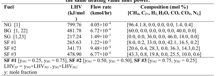
Table 3: Fuel specifications used in system simulation. All fuel flows are calibrated to give the same heating value inlet power.
Fuel LHV
(kJ/mol )
Flow rate
(kmol/hr) [CH4, CComposition (mol %) 2+, H2, H2O, CO, CO2, N2,]
NG [1] 799.76 4.05×10⁻⁴ [96.4
, 1.8, 0.0, 0.0, 0.0, 1.4, 0.4]
BG [1, 22] 481.78 6.72×10⁻⁴ [60.0, 0.0, 0.0, 0.0, 0.0, 40.0, 0.0]
SG [1,23] 217.24 1.49×10⁻³ [0.0, 0.0, 36.0, 0.0, 46.0, 18.0, 0.0]
SF #1 265.63 1.22×10⁻³ [8.0, 0.2, 33.0, 0.0, 42.1, 16.5, 0.2]
SF #2 341.73 9.48×10⁻⁴ [20.6, 0.4, 28.3, 0.0, 36.3, 14.3,0.2]
SF #3 478.90 6.77×10⁻⁴ [43.3, 0.8, 19.8, 0.0, 25.5, 10.0, 0.6]
SF #1 [yNG = 0.25, ySG = 0.75], SF #2 [yNG = 0.50, ySG = 0.50], SF #3 [yNG = 0.75, ySG = 0.25]
LHVSF = yNG×LHVNG + ySG×LHVSG;
y: mole fraction
Table 4: Simulation results.
Fuel i
(A/m2) (K) 𝐓𝐓� (K) ∆T Stack feed (reformate) composition (mol%) [H2, H2O, CO, CO2, N2]
el η
(%) th
η
(%)
System η
(%)
NG 1678 1219 121 [67, 7, 23, 3, 0] 62.7 22.4 85.1
BG 1387 1216 113 [51, 13, 28, 8, 0] 51.8 28.9 80.7
SG 770 1196 96 [30, 18, 31, 21, 0] 28.8 42.7 71.5
SF #1 990 1203 102 [37, 17, 30, 16, 0] 37.0 37.8 74.8
SF #2 1230 1210 108 [45, 15, 29, 10, 1] 45.9 32.5 78.4
20
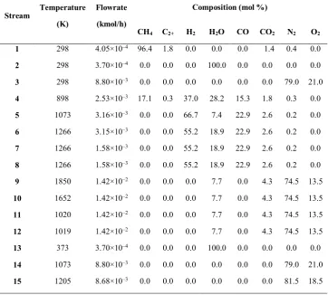
Table A1: Simulation results for NG fuelled system according to the flowsheet presented in Figure 2.
Stream Temperature (K)
Flowrate (kmol/h)
Composition (mol %)
21
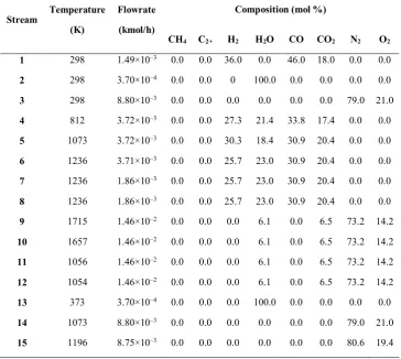
Table A2: Simulation results for BG fuelled system according to the flowsheet presented in Figure 2.
Stream Temperature (K)
Flowrate (kmol/h)
Composition (mol %)
22
Table A3: Simulation results for SG fuelled system according to the flowsheet presented in Figure 2.
Stream Temperature (K)
Flowrate (kmol/h)
Composition (mol %)
23
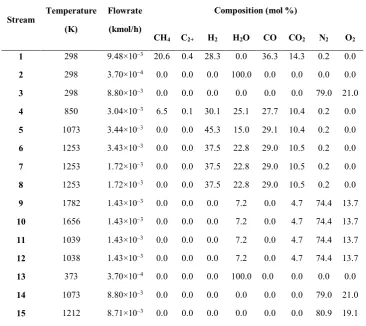
Table A4: Simulation results for SF#1 fuelled system according to the flowsheet presented in Figure 2.
Stream Temperature (K)
Flowrate (kmol/h)
Composition (mol %)
24
Table A5: Simulation results for SF#2 fuelled system according to the flowsheet presented in Figure 2.
Stream Temperature (K)
Flowrate (kmol/h)
Composition (mol %)
25
Table A6: Simulation results for SF#3 fuelled system according to the flowsheet presented in Figure 2.
Stream Temperature (K)
Flowrate (kmol/h)
Composition (mol %)
26
Figure 1: (A) Test rig flowsheet used with permission [16]; (B) Process flow diagram developed in this work to simulate the test rig flowsheet. The streams marked with ‘S’ are those monitored,
27
28
29
30
Figure 5: Local OCV and voltage loss elements along the cell/stack normalised length, x/LCell, for various fuel for assumed constant operating voltage, 0.80 V, justifiable considering the metallic
31
32
33
![Table 1: The model-based process streams (Figure 1) specifications results (M) compared to the experimental (E) results [16]](https://thumb-us.123doks.com/thumbv2/123dok_us/975093.1597009/17.842.176.683.117.505/process-streams-figure-specifications-results-compared-experimental-results.webp)


![Figure 1: (A) Test rig flowsheet used with permission [16]; (B) Process flow diagram developed in this work to simulate the test rig flowsheet](https://thumb-us.123doks.com/thumbv2/123dok_us/975093.1597009/26.595.58.516.94.634/figure-flowsheet-permission-process-diagram-developed-simulate-flowsheet.webp)