1
Risk of Excavators Overturning: Determining Horizontal
Centrifugal Force When Slewing Freely Suspended Loads
ABSTRACT
Purpose: Tracked hydraulic excavators are versatile and ubiquitous items of off-highway plant and machinery that are utilised throughout the construction industry. Each year a significant number of excavators overturn whilst conducting a lifting operation, causing damage to property, personnel injury or even fatality. The reasons for the overturn are myriad, including: operational or environmental conditions; machine operator acts or omissions; and/ or inadequate site supervision. Furthermore, the safe working load (SWL) figure obtained from manufacturer guidance and utilised in lift plans is based upon undertaking a static load only. This research seeks to determine whether the SWL is still safe to be used in a lift plan when slewing a freely suspended (dynamic) load, and if not, whether this may be a further contributory factor to overturn incidents.
Approach: Previous research has developed a number of machine stability test regimes but these were largely subjective, impractical to replicate and failed to accurately measure the ‘dynamic’ horizontal centrifugal force resulting from slewing the load. This research contributes towards resolving the stability problem by critically evaluating existing governing standards and legislation, investigating case studies of excavator overturn and simulating the dynamic effects of an excavator when slewing a freely suspended load at high rotations per minute (rpm). To achieve this, both the static load and horizontal centrifugal force from slewing this load were calculated for six randomly selected cases of an excavator, with different arm geometry configurations.
Findings: The results from the six cases are presented and a worked example of one is detailed to demonstrate how the results were derived. The findings reveal that the SWL quoted on an excavator’s lift rating chart considerably underestimates the extra forces experienced by the machine when an additional dynamic load is added to the static load whilst lifting and slewing a freely suspended load.
2 pre-programmed sensor based technology to monitor stability in real time and automatically restrict lift mode operations.
KEYWORDS: Tracked hydraulic excavator, freely suspended load, lifting chart, safe working load.
INTRODUCTION
Early items of off-highway plant and machinery shared a symbiotic linkage with their operators, representing a mechanical extension of human physicality, where human senses were transferred through machinery to complete physical work effort without exerting load upon the operator’s musculoskeletal frame (Edwards and Love, 2016). This pseudo-cybernetic organism led to manumission but remained dependent upon an operator’s cognitive ability to guide the machinery to complete predefined tasks (Edwards et al., 2003). Following work study, original equipment manufacturers (OEMs) acknowledged the impact of operator skill and competence upon machine productivity and safety performance, particularly when combined with adverse operational conditions (such as working on a slope or in confined spaces) and environmental conditions (such as unstable ground) (Wu et al., 2015). Although there followed a focus upon operator training and competence development, maximising machinery safety and productivity efficiency remained a persistent issue; indeed, accidents continue to plague industry (Zhou et al., 2015). The natural progression was for OEMs to
engineer-out human error, omissions or inactivity via the development of automation and robotics, for example, Volvo’s ‘Automatic Sensing Work Mode’ (Volvo, 2016).
3 2014); crushing and screening attachments (Bansal and Singh, 2015); compaction plates (Edwards et al., 2003); clamshells (Cruickshank et al., 2011); and hydraulic grabs for materials handling (Holt and Edwards, 2012). This versatility has evolved in a Darwinian manner as the excavator has been adapted to numerous working environments and the operational tasks required within these – such adaptability has caused excavators to be likened to Swiss army knives (Edwards et al., 2003).
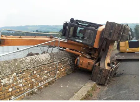
Despite excavator popularity and aforementioned attempts to engineer-out accidents due to human error (Edwards and Love, 2016), safety incidents continue to plague the construction industry; these include those categorised as struck by machine, crushing, reversing-over, falling objects and overturning. The focus of this research is to specifically investigate excavator overturn following a spate of fatal incidents internationally. Examples include: an operator in the United States who overturned an excavator operating in water and was drowned (Lezon, 2015); and operators in Australia (Akers, 2015) and Norway (Pourramedani, 2016) who overturned excavators and were crushed to death. Such accidents persist despite excavators incorporating several ‘engineered-in’ safety control systems such as out-riggers, roll over protection systems (ROPS) and safe working load (SWL) indicators. Past research has uncovered the inadequacies of the artificial and static tilt test for mini excavators (c.f. Edwards and Holt, 2009) and devised new field testing regimes to predict machine stability (Edwards and Holt, 2011). These latter field tests, which aimed to replicate machine operation, proved unworkable in practice because they were not only subjective and overly reliant upon expert judgement, but also, more critically, required an operator to potentially endanger themselves while conducting the trials. Consequently, industry resoundingly rejected this testing regime as the health and safety risks posed far exceeded the benefits accrued. However, these field tests advanced knowledge by identifying that the machine’s hydraulic slew speed (measured in rotations per minute (rpm)), particularly when used in lifting operations, created an additional dynamic force that impacted upon machine stability but could not [at the time] be measured accurately.
4 machines operating within the UK, demonstrating the inherent inaccuracy of current reporting mechanisms; ii) critical examination of existing standards and regulations that govern safe lifting operations with excavators; iii) a report upon observational evidence derived from case studies that highlight slewing at speed as one of the causal factors that contributes to excavators overturning; iv) mathematical modelling of the force exerted by the cumulative static and dynamic centrifugal forces derived as a result of slewing a machine handling a freely suspended load; and v) an evaluation of how the inclusion of the dynamic force from slewing impacts upon the SWL stated on a machine’s lift rating chart.
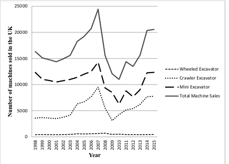
MACHINE PARK AND OVERTURN INCIDENTS: AN IMPRECISE SCIENCE The annual sales totals for excavators within the UK over the period 1998-2015 varied between circa 11,000 to 24,430 machines (Figure 1). For this total period, wheeled excavators accounted for 2.96% of total sales, crawler excavators accounted for 34.55% and mini excavators accounted for 62.49% of total sales. Determining the total number of excavators actually in operation within the UK in any given year (the so called machine park) is more difficult to establish in the absence of a comprehensive vehicle registration scheme. An arbitrary (rule of thumb) calculation used by some OEMs multiplies an average of the yearly published sales data for the most recent sales years (2008 to 2015) by an eight year average life expectancy which equals 123,030 excavator machines being operated in the UK at any given time. This rule of thumb is favoured because not all excavators have the same life expectancy. Mini excavators are normally depreciated over a three-five year period, although these machines may continue to work in the after-market (usually for sole traders who work them to destruction). Conversely, mid-range mass excavators (circa 20-45 tonnes) can operate beyond their average eight year life expectancy provided a robust system of fixed-time-to (or scheduled) maintenance is adhered to. It is difficult to be more accurate than this rule of thumb as first, not all OEMs publish their sales data and second, so called-grey machines (that is, non-conformant CE marked excavators) enter the UK market from countries outside the European Union (EU). Such machines fail European Union (EU) safety conformance standards of manufacture and pose a significant risk to health and safety.
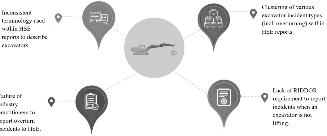
5 Reporting of Injuries, Diseases and Dangerous Occurrences Regulations (RIDDOR, 2013). Excavators used for lifting operations present an exception (LOLER, 1998) as RIDDOR requires reporting for the overturning of lifting plant as a dangerous occurrence. Second, interrogation of the RIDDOR database using a keyword search reveals various data entry inconsistencies. Instead of the word ‘mini, tracked or wheeled excavator’ being used to accurately describe the machine type, RIDDOR reports have a broad lexicon of terminologies including 360 degree, 180 degree, JCB, Komatsu, digger or any number of other permutations. This unstructured and organic growth of reports and terminologies used creates a huge keyword identification and filtering process to obtain a true picture of overturning incidents. Third, excavator overturns are grouped together by HSE statisticians with other incidents, e.g. crushed, trapped and overturning, thus further complicating database search procedures. Fourth, and perhaps of greater concern, is the issue of underreporting, such that confidence is low regards the accuracy of the number of overturns reported as a RIDDOR incident. One leading health and safety advisor suggested that:
“Larger contractors are more likely to be aware of, and report under, RIDDOR than others. Many companies may understand (to a greater or lesser extent) reporting of injuries but in my personal experience there is much less understanding of the need to report dangerous occurrences. So I would have little confidence in any figures we did produce as having any level of accuracy whatsoever.”
In contributing to this discourse, a health, safety and environmental director of a large construction contractor said:
6 Within the UK judicial system, fines imposed following a fatality can range from custodial sentence or community service to substantial fines and penalties (HSE, 2014).
Given the estimated volume of machines being used and this anecdotal evidence from industry practitioners, one would expect the reported rate of overturn to be higher than that reported by the HSE (refer to Table 1). Indeed, industry concern regarding machinery overturn whilst lifting and the inherent dangers it poses to worker safety, alongside concern about outdated HSE statistics, provided the catalyst for this investigative research work.
EXAMINATION OF EXISTING STANDARDS AND REGULATIONS
Excavators are increasingly being used for lifting [lifting and lowering] operations even though they are not specifically designed for this purpose as their primary function (CPA, 2009). When planning a lifting operation, a competent person should conduct a thorough risk assessment in accordance with The Management of Health and Safety at Work Regulations (MHSWR, 1999) to ensure that the lifting equipment (the excavator, including lifting accessories e.g. chains, slings, D-Shackles) are suitable for the lift, have been regularly maintained (PUWER 1998) and that the works can be carried out in a safe manner (HSE, 2013). Working in a safe manner includes: working on firm and level substrata, maintaining low rpm whilst slewing and excluding workers and pedestrians from the machine’s operational area (CPA, 2009). The risk assessment will also consider for example, whether the lifting equipment is: suitable for the proposed use and visibly marked with any appropriate information (such as SWL) (LOLER, 1998). All lifting equipment must be subject to a thorough examination, by a competent person, to detect any defects that are or may become dangerous (Oram, 2002). Accessories for lifting must be thoroughly examined either at least every six months, and the excavator every twelve months, or in accordance with an examination scheme (c.f. HSE, 2008). The machine’s SWLs at various arm geometries/ configurations are displayed on lift rating charts within the operator’s cab and are used to produce the lift plan, where BS ISO10567 2007 (BSI, 2007) provides a standard approach to determine the lift capacity for hydraulic excavators.
CASE STUDIES OF EXCAVATORS OVERTURNING
7
Case study #1:A stationary tracked excavator, operating on a level road surface, being used
to lift a mobile generator over a security hoarding surrounding a civil engineering site.
The lift plan identified that the generator specified for the task was within the SWL as identified by the lift rating chart for the excavator, but an overturn still occurred. Further investigation revealed that due to a shortage of the specific make and model of generator specified, the hire company had supplied an alternative, more powerful generator. This generator was also significantly heavier, exceeding the machine’s lift rating, but the original lift plan was not checked and revised. The excavator overturned and damaged the site hoardings, the generator being lifted and the machine itself – the operator (who was wearing seatbelt ‘lap’ restraint) incurred minor abrasions and bruising. Observers on-site reported that the operator was rushing to complete the lift before the lunchtime break and had slewed the machine at full rpm. One observer noted:
“The genni [generator] was swinging back and forth on the chains as the operator revved the machine up – you could tell he was rushing.”
Within the incident report, the overturn failure was attributed to: (1) poor communication between the contractor and the hire company within its supply chain; (2) operator error; and (3) failure of the operator/ site management to adequately check the lifting plans before initiating the lift (contrary to Regulation 8 of The Lifting Operations and Lifting Equipment Regulations (LOLER, 1998)). A plant operator on site said:
“The problem here is that we are under so much pressure these days to get everything done at lightning speed and it’s us [the operator] who have to educate this lot [site management] as to what they should be doing. I don’t get paid enough to be driving the machine, filling out paperwork and telling others, who are better paid than me, how to do their job!”
Case study #2:A 14 tonne wheeled machine being utilised to lift a concrete skip (alternatively
known as a ‘hopper’) to place wet concrete into a foundation.
8 it to overturn. Fortuitously, the foreman escaped with only minor injury and the machine incurred just slight damage. One observer stated:
“He [the foreman] should not have been on the machine and you could tell that he didn’t know how to operate it.”
However, having turned the machine over, the site foreman then ordered an operator of a 20 tonne tracked excavator to lift the 14 tonne machine to an upright position. For this impulsive second lift, there was again no lifting plan and it is by sheer luck that the 14 tonne machine was recovered despite it exceeding the load capacity of the 20 tonne machine. As a result of these two incidents, all staff involved (including site safety supervisory staff) were dismissed from employment. A senior safety advisor for the company said:
“This simple task was a disaster from start to finish and we’re very fortunate that no one was killed. We have a strict zero policy on these incidents and all our guys are aware that in the event of a machine overturning, we have specialist equipment to recover the machine. There was no excuse for this behaviour. The real problem stems from the fact that the wrong machine was initially selected - a concrete pump should have been hired. The foreman should have known better as he was an experienced worker and site safety personnel on site should never have allowed this to happen.”
Case study #3: An 18 tonne tracked excavator, equipped with rock grab, being used to create
a sea defence.
9 A combination of high slew drive speed, lack of familiarisation training and inadequate site supervision were all noted as causal factors contributing to this incident. A site safety officer added:
“This was a classic case of lone and inexperienced worker. The sea defence works were spread along the coast and one site manager had to travel by car up and down the coast to manage the works which consisted of up to eight tracked machines [excavators] and two ADTs [articulated dump trucks]. Hindsight is a wonderful thing, but we should have checked familiarisation training more carefully before employing these guys [the operator]. You would have thought that the banksman would have ensured that the machine operated at low revs [rpm] and operated on level ground – the operator could have easily created a bench to operate off. But the blame ultimately stops with us as the main contractor.”
Case study #4: A hired mini excavator equipped with a grading bucket operating on a
motorway embankment.
The mini excavator was operated by a groundwork labourer working for a sub-contractor employed by the main civil engineering contractor. The operator tracked diagonally across the embankment, slewing an empty grading bucket at full rpm, and the machine overturned. The operator had worn his lap restraint and no serious injury was incurred. The operator later stated that he did not check the rpm setting before operating the machine. He was unable to produce a valid competence card and consequently, was later dismissed. A hire subcontractor said:
“We often get machines back off hire for maintenance and repair that have the rpm on full throttle so it’s no wonder this occurred. The biggest problem with this incident though was the poor selection of machine – minis [mini excavators] are not well suited to working on gradients, especially, when slewing at high speed.”
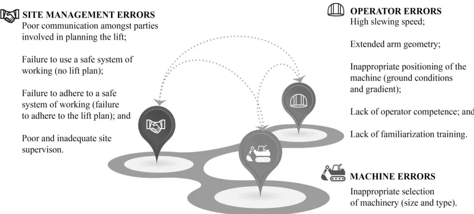
Causes of Excavator Overturning
10 would indeed probably be unaware of the need to. Nor was it apparent whether the machine’s SWL included this dynamic force. BS ISO10567 2007 (BSI, 2007) states that:
“Tipping load calculations shall be made at each grid line intersection of a 0.5m, 1m or 2m vertically and horizontally spaced grid placed over the excavator’s working range. The origin of the grid shall be at the intersection of the ground reference plane (GRP) and the axis of rotation. The tipping load calculations shall be made to determine the load that can be lifted with the machine at its balance point.”
The SWL provided in a manufacturer's lift rating charts is based upon a combination of contributory factors, including: the excavator arm geometry (taking into account the dipper and boom length); and whether the lift is being undertaken at the front, rear (longitudinal stability) or side (lateral stability) of the machine. Whichever combination of factors is present during a lifting operation, the lift capacity provided is based upon the forces produced from lifting a static load and fail to account for the additional forces produced by a dynamic lift (where for example, a load is lifted at the front of the machine then slewed to a lateral position to set it down). The dynamic aspect introduces an extra horizontal load caused by the centrifugal force of slewing as the excavator superstructure rotates. Therefore, the SWL quoted in the machine’s cab may not provide complete and accurate information that would allow a robust lift plan to be prepared for this specific operational activity. In theory, this may explain why adequate lifting plans can still result in a machine overturn when slewing at high rpm – as in the second case study presented earlier in this paper.
METHODOLOGY
11 slewing were in effect. Future work will be required to assess the impact of the variables kept constant in this investigation. A full worked example is presented to further elucidate upon the methodology and mathematical calculations undertaken to derive these results prior to discussing the implications of this research for contemporary practice and current international standards. By including a worked example, other researchers and practitioners will be able to readily reproduce the results for specific machine configurations being utilised on site (taking into account bespoke arm geometries) vis-à-vis relying upon static SWLs quoted by OEMs.
The methodology and mathematical approach used to identify the impact of the additional horizontal forces upon an excavator undertaking a dynamic lift (i.e. lifting and slewing) were validated through three main ways. First, the individual impact of five machine components upon the righting and overturning moments acting upon the excavator when undertaking a ‘static’ lift were calculated (i.e. boom, dipper, undercarriage, balanced superstructure and counterweight and engine), using the premise that the machine was known to be in equilibrium using SWL guidance. This knowledge could then be applied to the calculations for the ‘dynamic lift’, the impact of which was as yet unknown. Second, the pivot point of turning (i.e. the tipping edge at which the excavator would overturn) needed to be established. The calculations applied to this were cross referenced and validated against OEM literature. Third, to establish the ‘dynamic forces’ which were added to the ‘static forces’, mathematically proven centrifugal force calculations (Bohacek et al., 2018) were applied, prior to comparison against the manufacturer’s SWL that were based upon a static load only.
Determining the Impact of Dynamic Forces Upon an Excavator’s SWL
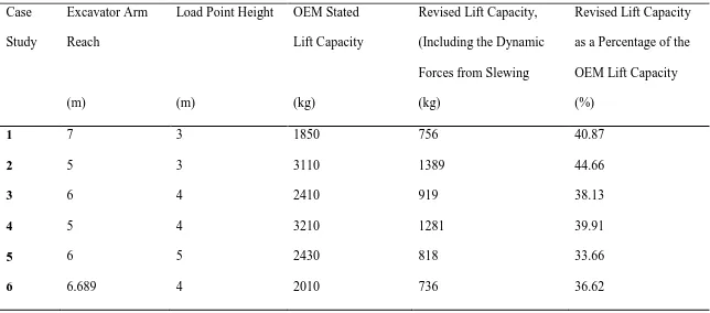
12 was reduced to between a third and two thirds of those stated on the load chart (refer to the last column of Table 2). Although these are significant and consistent results, it should be noted that they are only applicable to the machine selected in this study, operating at a slewing speed of 13.3 rpm and with a lifting attachment length of 2m. The first of the six cases will now be worked through in detail to demonstrate how the results were derived.
Calculating the Forces from Undertaking a Static Lift
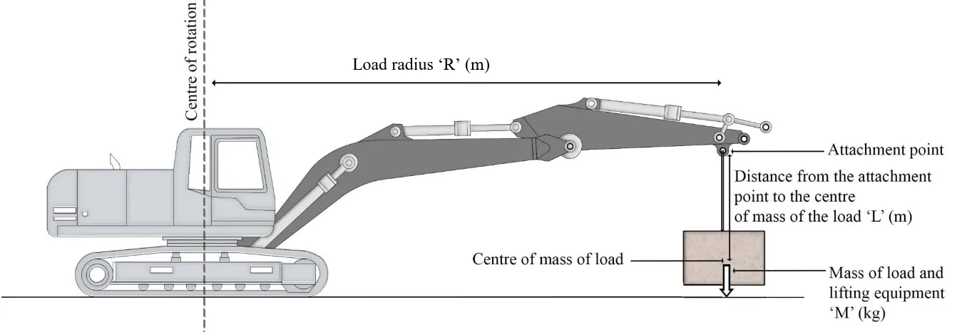
When an excavator undertakes a static lift of a load 'M' (where the load includes the item being lifted and any lifting equipment used), then the force from that load acts vertically at the point of attachment, at load radius 'R' (Figure 5), and exerts an overturning effect - or moment - on the machine. Working against this overturning is the righting moment produced by the weight of the excavator body components and counterweight. In order to maintain equilibrium and prevent the excavator from tipping over, the overturning moment from lifting a load must be in balance with the righting moment of the machine. The maximum SWL that can be safely lifted to maintain equilibrium, for a specific arm geometry, is provided in the machine manufacturer's lift charts.
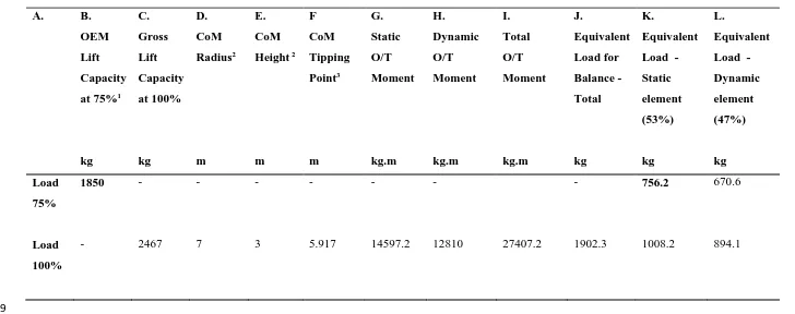
In the worked example (Table 3), the arm configuration selected is at a reach of 7m (Table 3, col D) and a load point height of 3m (Table 3, col E). The SWL provided in the manufacturer lift charts for a lateral lift at this arm geometry is 1,850kg (Table 3, col B). As this lifting capacity is based on ISO 10567 (75% of the tipping load) the load is grossed up to 100% at 2,467kg (Table 3, col C) for the purposes of the calculations and reduced back to the 75% figure at the end for comparison.
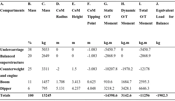
13 Although this overturning moment is balanced by the overall righting effect of the excavator body and counterbalance, some of the individual excavator body components do actually increase the overturning effect, namely the boom and dipper. This was proven by separating the machine into five components, namely the boom, dipper, undercarriage, balanced superstructure and counterweight and engine (see Table 4) and calculating their individual impacts upon the moments acting upon the excavator.
For each component, the height to the centre of mass and the radius from the centre of rotation were obtained from manufacturer specifications and diagrams (Table 4, col D and E) and in each case the radius was again adjusted for the offset from the tipping edge (Table 4, Col F). The mass of each component (Table 4, col C) was initially an estimation from available specifications, but as the machine was known to be in equilibrium, this component mass distribution was then refined until the total combined righting moment -14,398.60kgm (Table 4, col G) was close to balancing the overturning moment 14,597.2 kg. The imbalance of 198.6 kgm, at 5.917 m radius, produced a difference in gross load of 33.56kg, or 1.36% of the gross load (2,467 kg) - this was deemed to be an acceptable level of accuracy.
Upon examination of the separate component turning moments (Table 4, Col G), as expected the boom and dipper added to the overturning moment of the load, but the larger righting moments of the more central undercarriage, balanced superstructure, engine and counterweight meant that the machine components combined provided an overall righting balance to maintain equilibrium.
Calculating the Additional Horizontal Forces from Undertaking a Dynamic Lift
When an excavator undertakes a dynamic lift of the same load 'M', the action of slewing the load to a designated drop point creates an extra force (see Figure 7). This force is a centrifugal force 'P' caused by rotation of the load and it acts horizontally at the attachment point height 'H' above ground level of the excavator. The higher the height the load is being slewed, then the larger the effect of the force.
14 force also acts along the radius of the circle, but from the load towards the centre of rotation, keeping the load moving in a curve around the excavator and preventing it from flying out.
The circular motion of the load as it is slewed is accelerated motion, therefore the centrifugal
force P is calculated as P = mass x acceleration. Acceleration is defined as
R 2
where v =
velocity and R = radius), thus:
R mass P 2 Eq.1
After substituting for velocity (distance/time) with T
R
2 , where T = 1/ (rpm/60) (i.e. the
time taken to complete one 360˚ rotation of distance 2𝜋𝑅), and rpm is rotations per minute, by calculation and transposition the formula becomes:
Eq. 2 81 . 9 011 . 0 2
mass R rpm
P
Note: the force P measured in Newtons (N) is converted to kilogram (kg) by dividing by 9.81.
15 ΔdR = the change in radius; L = the distance from the attachment point to the centre of mass of the load; P = the horizontal centrifugal load; E = the tension load; M is the static load.
In a second iteration, as the distance from the slewing load to the centre of rotation increased, a new equivalent horizontal force P2 was calculated, from slewing load P1 at the revised radius
R1 and resulted subsequently in a new revised load radius R2. After three iterations, the difference in the new and previous equivalent horizontal force and radius were small enough to deem them suitably accurate values, hence no further iterations were required (refer to Figure 9).
The moment due to the centrifugal force caused by the excavator lifting and slewing the load could then be calculated. From the iterative process above, the final equivalent horizontal force
P generated from slewing (calculated as 4,270 kg) was multiplied by the height of the attachment point where the force is acting (in this case 3m), creating an overturning moment due to slewing of 12,810 kg.m (Table 3, col H).
Next, the effect of the slewing on each of the five excavator components was calculated. The height to the centre of mass H (Table 4, col E) was multiplied by the centrifugal force P of each component, calculated using equation 2 earlier, substituting the mass of the component (Table 4, col C), the radius from the centre of rotation (Table 4, col D) and the machine rpm of 13.3.
There was an expectation that the effect of the centrifugal force on the rotating excavator superstructure would result in a slight reduction in the overall tipping effect. However, upon examination of the moments due to the slewing (Table 4, col H), it is apparent that they actually increase the overturning moment by in total 3,142.6 kg.m. There are a number of reasons to explain this. The effect of the rotating element is based on the distance from the centre of rotation not the greater distance from the tipping edge of the track used for the static stability. Furthermore, the undercarriage is not rotating so does not make a contribution to the dynamic stability; the balanced part of the superstructure likewise makes no contribution as its centre of mass is at the centre of rotation. Finally, the counterweight and engine are relatively close to the ground which reduces their dynamic effect and provides the only righting effect.
16 When the moments calculated for the static effect (Tables 3 and 4, col G) and the dynamic effect (Tables 3 and 4, col H) of lifting and slewing the load M were combined (Tables 3 and 4, col I), an imbalance was clearly apparent as the total restoring moment was reduced to 11,256 kg.m and the total overturning moment was increased to 27,407.2 kg.m. For the excavator undertaking the dynamic lift to be back in balance then the maximum overturning moment needed to once again equal the restoring moment, thus the load being lifted had to be reduced. Using force = load x distance, the equivalent load needed for balance was calculated as 11,256 divided by the distance 5.917 (Table 3, col F) which is 1,902.3 kg (Tables 3 and 4, col J). However, the total load was made up of two components, the first resulting from the static vertical component (load M) and the second from the dynamic centrifugal force (load P). The balance between the static overturning moment (Table 3, col G) and the slewing overturning moment (Table 3, col H) was 53% and 47% respectively, therefore the load was split across the two components in the same ratio, i.e. 1008.2 kg for the static vertical component and 894.1 kg for the dynamic centrifugal component (Table 3, col K and L). These are gross loads so to produce a revised chart figure they were reduced back down to 75%. When the original lift capacity for this excavator configuration of 1,850kg (Table 3, col B) is compared to the revised figure of 756.2 kg (Table 3, col K) for the vertical static component, which now takes account of the effect of slewing the load at the speed of 13.3rpm, there is a significant difference as it is reduced by 59.12%.
IMPLICATIONS AND FUTURE RESEARCH
17 calculating a tracked hydraulic excavator’s stability (based upon a sum of static and dynamic loads) illustrates that the OEMs’ quoted SWL may be reduced significantly as a result of the dynamic load especially when operating at full RPM. Consequently, machine overturning incidents occurring could theoretically occur even when operators and site management have taken every reasonable precaution and used OEM SWL data to develop a lift plan. Linking past machine overturning events to the omission of this dynamic effect is impossible to achieve because stability is dependent upon many other factors and reporting of incidents lacks accuracy and completeness, and often contains retrospective analysis which is subject to bias (c.f. Kessels-Habraken et al., 2009).. Nevertheless, this research illustrates that a significant risk factor is not accurately factored into lift plan calculations. In response to the findings presented, several UK construction and civil engineering contractors have already implemented measures to reduce the SWL load ratings by as much as 50% of those quoted by OEMs, thus integrating an additional factor of safety into any future lift plans developed.
Such temporary action may act as a useful stop-gap but future research and development is urgently needed as the scientific evidence presented herein is compelling. Future work may include industry 4.0 innovations (c.f. Junior et al., 2018) that model the impact of other factors that impact upon machine stability, e.g. different machine weights, arm configurations and slewing speeds. This could then be used to develop sensor based technology to measure stability characteristics in real time. At present, commercially available safe load indicators are based upon pre-programmed independent static load testing of the machine conducted by the device manufacturer. So whilst such may present a better indication of lifting risk, it still fails to predict the dynamic effects of lifting and moving a load. Industry 4.0 and sensor based technology development would ideally need to intelligently model static, dynamic, environmental and operational factors simultaneously and so considerable computational power and expense may be required. A solution lies with mobile communications via cloud technology which have removed this financial barrier (and increased computational power) by allowing internet connected devices to communicate algorithmically via the cloud, providing excavator machines with accurate information and instruction on machine stability.
18 for example, Volvo’s new fully automatic rpm system that predicts the speed needed for various configurations of machine operation. One practitioner stated:
“Volvo’s system looks to be a great innovation and we anticipate that it should be able to differentiate between digging (where speed and break-out force is needed) and lifting mode (where speed should be kept to an absolute minimum).”
Additional research is also urgently required through work in conjunction with OEMs and other industry stakeholders via international standards development, to improve information and instruction issued throughout industry. Two areas of development are immediately apparent. First, lift rating charts and operations and maintenance handbooks supplied with machines should be updated with new information to notify operators that the SWL indicated is for a static lift only or updated to include dynamic forces. Whilst this latter update is being implemented, the SWL of existing machines should be halved for all lifting operations that involve slewing. Second, BS ISO 10567:2007 (BSI, 2007) should be revised to better reflect the dynamic load imposed upon a machine as a result of the horizontal centrifugal force such that future SWL quoted more accurately reflect the full load exerted upon machine stability whilst slewing.
Engineering-out the risk is another prominent area of future work that should be pursued by OEMs as such would include automatically lowering a machine’s rpm to a minimum whilst slewing with a load. This simple action would reduce the centrifugal force to a minimum thus, ensuring that machine stability is enhanced and associated risk of overturn minimised.
CONCLUSION
19 The SWL stipulated on a machine’s load chart has historically provided the main source of information used to assess the risk of tracked hydraulic excavators overturning when producing a lifting plan. Yet this research reveals that the SWL is applicable to a static lift only and that when the load is freely suspended and slewed, an additional horizontal centrifugal force is exerted upon the machine’s stability. Using the new method presented in this paper for calculating a tracked hydraulic excavator’s SWL, practitioners can better estimate machine instability risk posed and employ appropriate risk mitigation control measures (such as reducing the size of load to be lifted, using a larger machine and/or lowering the rpm to a minimum level). Additional work is, however, needed to: i) model all factors that impact upon machine stability using industry 4.0 and supporting technological innovations in sensor based systems, cloud computing and computational intelligence. In coalescence, these technologies appear at this stage to present the best opportunity to mitigate the risk of turnover; ii) further develop international standards for hydraulic excavator lift capacity and ensure that adequate information and instruction accompanies all machines sold. Such information could alert operators and safety managers to the fact that SWLs are based upon a static lift only and that additional risks may be involved when slewing, hence the need to maintain low rpm. Alternatively, and indeed preferably, lift charts should be revised to take account of these dynamic forces; and iii) engineer-out potential hazards within excavator machines (such as slewing at high speed) to automatically reduce the risk posed and eliminate operator error or abuse.
It would appear from case study evidence, that accidents often arise due to human or management error and the standard response to this has been to take legal action against the operator without questioning the SWL data input into lift plans. This research sheds new light upon past preconceptions and illustrates that more needs to be done by OEMs to provide more comprehensive, complete and accurate information on SWLs for an excavator machine. Moreover, any future incidents occurring should use the new method of calculating SWLs presented herein to assess whether the operator was actually at fault. Such work is dependent upon better and more consistent reporting of incidents occurring, analysis of such, and far greater transparency within industry and knowledge sharing between practitioners. Failure to implement the recommendations made within this paper will result in continued and sustained reoccurrence of excavator overturning incidents.
20 The authors wish to extend their thanks and gratitude to Mr Steve Cribbin, Chief Engineer, Balfour Beatty Civil Engineering; Mr Richard Sharp, Former Chief Economist at JCB; and Mr Paul Kerridge, Health, Safety and Environment Director, Mr Jeremy Elvin, Morrison Plant Fleet and Services Director and Mr Mark Dixon, Morrison Plant and Services Safety and Health Manager at Morrison Utility Services; Mr Patrick Flannery and Mr Martin Flannery, Flannery Plant Hire (Oval) Ltd; and Dr Iain Rillie, Highways England.
DEDICATION
21 REFERENCES
Abudayyeh, O., Sawhney, A., El-Bibany, H., and Buchanan, D. (1998) Concrete Bridge Demolition Methods and Equipment, Journal of Bridge Engineering, Vol. 3, No. 3, pp. 117-125.
Akers, T. (2015) Man Sustains Fatal Injuries After Excavator he was Driving Overturned and Crushed Him, The Courier Mail, Brisbane, Australia. Available via: http://www.couriermail.com.au/news/queensland/man-sustains-fatal-injuries-after-
excavator-he-was-driving-overturned-and-crushed-him/news-story/f0174819b787e781a3bc8edd683263dd (Accessed on: 15th May 2016)
Bansal, S. and Singh, S.K. (2015) Sustainable Handling of Construction and Demolition (C&D) Waste, International Journal of Sustainable Energy and Environmental Research, Vol. 4, No. 2, pp. 22-48.
Barsottelli, M and Avci, O. (2013) Fundamentals of Highway Bridge Demolition, ASCE Structures Congress, Pittsburgh, Pennsylvania, 2-4 May, pp. 680-688.
Bohacek, J., Kharicha, A., Ludwig, A., Wu, M. and Karimi-Sibaki, E. (2018) Heat Transfer Coefficient at Cast-Mold Interface During Centrifugal Casting: Calculation of Air Gap, Metallurgical and Materials Transactions B, Vol. 49, No. 3, pp. 1421–1433.
BSI (2007) BS ISO 10567: 2007. Earth-moving Machinery – Hydraulic Excavators – Lift Capacity, 2nd Edition 2007-10-01, British Standards Institute, London. ISBN: 978 0 580 54268 8
Chanda, E.K. and Gardiner, S. (2010) A Comparative Study of Truck Cycle Time Prediction Methods in Open‐pit Mining, Engineering, Construction and Architectural Management, Vol. 17 No. 5, pp. 446 – 460
Coelho, A. and de Brito, J. (2011) Economic Analysis of Conventional Versus Selective Demolition – A Case Study, Resources, Conservation and Recycling, Vol. 55, No. 3, pp. 382-392.
CPA (2009) Guidance on Lifting Operations in Construction When Using Excavators, Construction Plant Hire Association, London.
Cruickshank, M.G., Morrison, D.J. and Lalumière, A. (2011) Site, Plot, and Individual Tree Yield Reduction of Interior Douglas-Fir Associated with Non-Lethal Infection By Armillaria Root Disease In Southern British Columbia, Forest Ecology and Management, Vol. 261, No. 2, pp. 297-307.
22 Edwards, D.J. and Holt, G.D. (2009) New Stability Field Tests For Construction Excavators, Engineering, Construction and Architectural Management. Vol. 16, No. 4, pp. 337-352. Edwards, D.J. and Holt, G.D. (2011) Mini-Excavator Safety: Towards Innovative Stability
Testing, Procurement, and Manufacture, ASCE Journal of Construction Engineering and Management, Vol. 137, No. 12, pp. 1125-1133.
Edwards, D.J. and Love, P.E.D. (2016) A Systemic Risk Maintenance Model for Machinery, Accident, Analysis and Prevention. Vol. 93, pp. 319-329.
Edwards, D.J., Pärn, E.A., Love, P.E.D., and El-Gohary, H. (2016) Machinery, Manumission and Economic Machinations, Journal of Business Research, in press.
Gondek, H., Neruda, J. and Pokorný, J. (2014) The Dynamics of Impacts Tools the Loading Boom Bucket Wheel Excavators, Applied Mechanics and Materials, Vol. 683, pp. 213-218.
Hajji, A.M. and Lewis, P. (2013) Development of Productivity‐based Estimating Tool for Energy and Air Emissions from Earthwork Construction Activities, Smart and Sustainable Built Environment, Vol. 2 Iss: 1, pp.84 – 100
Hola, B. and Schabowicz, K. (2010) Estimation of Earthworks Execution Time Cost by Means of Artificial Neural Networks, Automation in Construction, Vol. 19, No. 5, pp 570-579. Holland, G.J., Webster, P.J., Curry, J.A., Tyrell, G., Gauntlett, Brett, D., Becker, J., Hoag, R. and Vaglienti, W. (2001) The Aerosonde Robotic Aircraft: A New Paradigm for Environmental Observations. American Meteorological Society, Vol. 82, No. 5, pp. 889– 901.
Holt, G. and Edwards, D.J. (2013) Analysis of United Kingdom Off-Highway Construction Machinery Market and Its Consumers Using New-Sales Data. ASCE Journal of Construction, Engineering and Management Vol. 139, No. 5, pp 529–537.
HSE (2008) Thorough Examination of Lifting Equipment: A Brief Guide, INDG422, Health
and Safety Executive, London, Available via:
http://www.hse.gov.uk/pubns/indg422.pdf (Accessed on: 1st May 2016).
HSE (2013) Lifting Equipment at Work: A Brief Guide, INDG290, Health and Safety Executive, London, Available via: http://www.hse.gov.uk/pubns/indg290.pdf (Accessed on: 1st July 2016)
23 ISO (2009) Earth-moving Machinery: Hydraulic Excavators - Terminology and Commercial Specifications, International Organisation for Standardization: Geneva.Junior, J.A.G., Busso, C.M., Gobbo, S.C.O and Carreão, H. (2018) Process Safety and Environmental Protection, Process Safety and Environmental Protection, Vol. 117, pp 372-382.
Kessels-Habraken, M., Van der Schaaf, T., De Jonge, J., Rutte, C. and Kerkvliet, K. (2009) Integration of Prospective and Retrospective Methods for Risk Analysis in Hospitals, International Journal for Quality in Health Care, Vol., No. 6, pp 427–432.
Kozan, E. and Liu, S.Q. (2016) A New Open-pit Multi-stage Mine Production Timetabling Model for Drilling, Blasting and Excavating Operations, Mining Technology: Transactions of the Institutions of Mining and Metallurgy: Section A, Vol. 125, No. 1, pp 47-53.
Lezon, D. (2015) Overturned Excavator Pins Construction Worker, Chron, Houston, Tx. Available via: http://www.chron.com/houston/article/Overturned-excavator-pins-construction-worker-6696836.php (Accessed on: 15th May 2016)
LOLER (1998) The Lifting Operations and Lifting Equipment Regulations, Statutory
Instrument 1998, No. 2307. Available via:
http://www.legislation.gov.uk/uksi/1998/2307/made/data.pdf (Accessed on: 22nd May 2016)
McMichael, P. (2000) World-Systems Analysis, Globalization, and Incorporated Comparison, Journal of World-Systems Research, Vol. 6, No. 3, pp 668-690.
MHSWR (1999) The Management of Health and Safety at Work Regulations 1999, Statutory
Instrument No. 3242. Available via:
http://www.legislation.gov.uk/uksi/1999/3242/contents/made (Accessed on: 23rd May, 2016)
Nakagawa, M., Hayashi, N. and Narushima, T. (2010) Effect of Tree Size on Time of Each Work Element and Processing Productivity Using an Excavator-based Single-grip Harvester or Processor at a Landing, Journal of Forestry Research, Vol. 15, No. 4, pp 226-233.
Oram, P. (2002) Thorough Examination and Inspection of Particular Items of Lifting Equipment, Contract Research Report 429/2002, Health and Safety Executive, London. Available via: http://www.hse.gov.uk/research/crr_pdf/2002/crr02429.pdf (Accessed on: 15th May, 2016).
24 Pourramedani, A. (2016) Man has Lost his Life in an Excavator Accident in Lom, Norway Today, Oslo, Norway. Available via: http://norwaytoday.info/news/man-lost-life-excavator-accident-lom/ (Accessed on: 16th May 2016)
Pun, S.K., Liu, C and Langston, C. (2006) Case Study of Demolition Costs of Residential Buildings, Construction Management and Economics, Vol. 4, No. 9, pp 967-976. PUWER (1998) The Provision and Use of Work Equipment Regulations 1998, Statutory
Instrument No. 2306. Available via:
http://www.legislation.gov.uk/uksi/1998/2306/contents/made (Accessed on: 23rd May, 2016)
Qin, T., Gu, X. Tian, Z. and Deng, J. (2015) Comparison of Agriculture and Forestry Fiscal Subsidy Policies in China, Journal of Sustainable Forestry, Vol. 8, No. 34.
RIDDOR (2013) The Reporting of Injuries, Diseases and Dangerous Occurrences Regulations, Statutory Instrument 2013, No. 1471. Available via: http://www.legislation.gov.uk/uksi/2013/1471/pdfs/uksi_20131471_en.pdf (Accessed on: 22nd May 2016).
Rusinski, E., Cegiel, L., Michalczyk, A., Moczko, P., Olejarz, J. and Pietrusiak, D. (2015), Investigation and modernisation of bucket of Surface Mining Machines, Engineering Structures, Vol. 90, pp. 29-37.
Seo, J., Lee, S., Kim, J. and Kim, S-K. (2011) Task Planner Design for an Automated Excavation System, Automation in Construction, Vol. 20, No. 7, pp. 954-966.
Shaurette, M. (2015) Higher Hourly Cost Compensation for Heavy Equipment Used in Demolition Activity, International Journal of Construction Education and Research, Vol. 11, No. 4, pp 280-291.
Taylor, K.M. and Vachon, S. (2018) Empirical Research on Sustainable Supply Chains: IJPR’s Contribution and Research Avenues, International Journal of Production Research, Vol. 56, No. 1-2, pp. 950-959.
Tiwari, R., Knowles, J. and Danko, G. (2013) Bucket Trajectory classification of Mining Excavators, Automation in Construction, Vol. 31, pp. 128-139.
Volvo (2016) Volvo Excavator: Long Crawler / Narrow Long Crawler Monobloc / 2-Piece Boom, Volvo Construction Equipment Group, Seoul. Available via: https://www.volvoce.com/SiteCollectionDocuments/VCE/History/07__crawler%20exc
25 Wang, J., Yang, Z., Liu, S., Zhang, Q. and Han, Y. (2016) A Comprehensive Overview of Hybrid Construction Machinery, Advances in Mechanical Engineering, Vol. 8, No. 3, pp. 1–15
Wu, X., Liu, Q., Zhang, L., Skibniewski, M.J. and Wang, Y. (2015) Prospective Safety Performance Evaluation on Construction Sites, Accident Analysis and Prevention, Vol. 78, pp. 58-72.
26 Figure 1 – UK excavator sales 1998-2015
0 5000 10000 15000 20000 25000 19 98 19 99 20 00 20 01 20 02 20 03 20 04 20 05 20 06 20 07 20 08 20 09 20 10 20 11 20 12 20 13 20 14 20 15 Num b er of m ac h in es sold in the U K Year Wheeled Excavator Crawler Excavator Mini Excavator
28 Figure 3 – Reasons for inaccurate/ incomplete overturn data
Inconsistent terminology used within HSE reports to describe excavators .
Failure of industry practitioners to report overturn incidents to HSE.
Clustering of various excavator incident types (incl. overturning) within HSE reports.
29 Table 1 – Excavator incidents 2005-2010
Fatal Major Over 3 days
Struck by 14 155 178
Falling objects 5 74 69
Crushed/trapped/ overturning
7 33 57
Fall from height 1 5 5
31 Table 2 – A Comparison Between OEM Stated Lift Capacity and Revised Lift Capacity Including the Slewing Effect
1
Case
Study
Excavator Arm
Reach
(m)
Load Point Height
(m)
OEM Stated
Lift Capacity
(kg)
Revised Lift Capacity,
(Including the Dynamic
Forces from Slewing
(kg)
Revised Lift Capacity
as a Percentage of the
OEM Lift Capacity
(%)
1 7 3 1850 756 40.87
2 5 3 3110 1389 44.66
3 6 4 2410 919 38.13
4 5 4 3210 1281 39.91
5 6 5 2430 818 33.66
6 6.689 4 2010 736 36.62
32 Figure 5 - Excavator with freely suspended load: side view – static case no rotation.
3
4
5 6 7
33 Table 3 – Determining the impact of the dynamic forces from slewing upon the SWL – The Load
8
A. B.
OEM
Lift
Capacity
at 75%1
kg C. Gross Lift Capacity at 100% kg D. CoM Radius2 m E. CoM
Height 2
m F CoM Tipping Point3 m G. Static O/T Moment kg.m H. Dynamic O/T Moment kg.m I. Total O/T Moment kg.m J. Equivalent Load for Balance - Total kg K. Equivalent
Load -
Static element (53%) kg L. Equivalent
Load -
Dynamic element (47%) kg Load 75%
1850 - - - 756.2 670.6
Load
100%
- 2467 7 3 5.917 14597.2 12810 27407.2 1902.3 1008.2 894.1
9
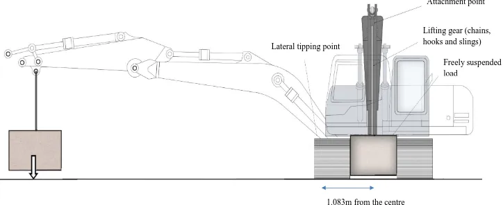
34 Figure 6 – Excavator with freely suspended load: longitudinal view superimposed with lateral view to show the lateral tipping point.
10
11 12
Lateral tipping point
Attachment point
Lifting gear (chains, hooks and slings)
Freely suspended load
35 Table 4 – Determining the impact of the dynamic forces from slewing upon the SWL – machine compartments
13 A. Compartments B. Mass % C. Mass kg D. CoM Radius m E. CoM Height m F. CoM Tipping Point m G. Static O/T Moment kg.m H. Dynamic O/T Moment kg.m I. Total O/T Moment kg.m J. Equivalent Load for Balance
kg Undercarriage 38 5033 0 0 -1.083 -5450.7 0 -5450.7 Balanced
superstructure
20 2649 0 0 -1.083 -2868.9 0 -2868.9
Counterweight and engine
25 3311 -2 1.5 -3.083 -10207.8 -1970.2 -12178
Boom 11 1457 1.708 3.413 0.625 910.6 1684.7 2595.3 Dipper 6 795 5.131 4.237 4.048 3218.2 3428.1 6646.3
Totals 100 13245 -14398.6 3142.6 -11256 -1902.3
36 Figure 7 - Excavator with freely suspended load: side view – centrifugal force rotating case
15
37 Figure 8 – Calculating the increase in the swing radius
19 20 21 22
23 24 25
26 27 28 29 30 31 32 33
Distance from attachment point to centre of mass
of load L Tension load
E
Static load M
Horizontal centrifugal load
P
Change in radius
38 Figure 9 – Illustration of the revised force and increase in swing radius per iteration
34