http://www.sciencepublishinggroup.com/j/ajnna doi: 10.11648/j.ajnna.20180401.12
ISSN: 2469-7400 (Print); ISSN: 2469-7419 (Online)
Architecture of the Extended-Input Binary Neural Network
and Applications
Wafik Aziz Wassef
Department of Computer Engineering, Saskatchewan Institute of Applied Science and Technology, Moose Jaw, Canada
Email address:
To cite this article:
Wafik Aziz Wassef. Architecture of the Extended-Input Binary Neural Network and Applications. American Journal of Neural Networks and Applications. Vol. 4, No. 1, 2018, pp. 8-14. doi: 10.11648/j.ajnna.20180401.12
Received: June 4, 2018; Accepted: June 20, 2018; Published: July 6, 2018
Abstract:
The proposed architecture of a binary artificial neural network is inspired by the structure and function of the major parts of the brain. Consequently it is divided into an input module that resemble the sensory (stimuli) area and an output module similar to the motor (responses) area. These two modules are single layer feed forward neural networks and have fixed weights to transform input patterns into a simple code and then to convert this code back to output patterns. All possible input and output patterns are stored in the weights of these two modules. Each output pattern can be produced by a single neuron of the output module asserted high. Similarly each input pattern produces a single input module neuron at binary 1. The training of this neural network is confined to connecting one output neuron of the input module at binary 1 that represents a code for the input pattern and one input neuron of the output module that produces the desired associated output pattern. Thus fast and accurate association between input and output pattern pairs can be achieved. These connections can be implemented by a crossbar switch. This crossbar switch acts similar to the thalamus in the brain which is considered to be a relay center. The role of the crossbar switch is generalized to an electric field in the gap between input and output modules and it is postulated that this field may be considered as a bridge between the brain and mental states. The input module encoder is preceded by the extended input circuit which ensures that the inverse of the input matrix exists and at the same time to make the derivation of this inverse of any order a simple task. This circuit mimics the processing function of the region in the brain that process input signals before sending them to the sensory region. Some applications of this neural network are: logical relations, mathematical operations, as a memory device and for pattern association. The number of input neurons can be increased (increased dimensionality) by multiplexing those inputs and using latches and multi-input AND gates. It is concluded that by emulating the major structures of the brain using artificial neural networks the performance of these networks can be enhanced greatly by increasing their speed, increasing their memory capacities and by performing a wide range of applications.Keywords:
Architecture, Modular, Pattern Association, Mathematical Operations1. Introduction
In designing the architecture of the present binary neural network an attempt is made to emulate the major parts of the brain and their interconnections. This approach may help us to improve the performance of artificial neural networks and at the same time enhances our understanding of the functions of the various parts of the brain. One obvious feature of the brain is the division or separation between the areas of sensory and motor functions. This feature is implemented by introducing two modules: input and output modules. It is known as well that the input signals are processed for the extraction of information at the sensory area before sending
the next section. It is found, in order that the inverse of the extended input matrix to exist and thus we may obtain a unique output, the number of the original input neurons must be increased to match the total number of input states that the original input neurons may assume. Consequently the number of these original inputs must be extended by adding extra inputs derived from the original inputs by nonlinear digital gates. Thus the total number of input neurons and their connecting weights increase exponentially with the increase of the number of original inputs as will be shown in the next section. Complexity in this case is due to a mathematical necessity.
Another feature of biological neural networks is that they contain two types of synapses: excitatory and inhibitory. This fact was found automatically to be the case in the neural network of the input module connected to the output of the extended input circuit where all the deduced non-zero weights of this module assume only two values, namely +1 and -1.
The association of input stimuli with output responses of biological neural networks are one of their most important functions. There are several artificial neural networks that perform similar task [3] by associating input and output patterns such as the Bidirectional Associative Memory (BAM) [4, 5]. These networks need to be trained in order to learn these associations by adjusting their synaptic weights. However the nervous systems of many organisms contain parts, such as the retina, [6] which are already wired before the organism gains any experience from its environment. This feature is emulated in the design of the input and output modules which contain fixed weights for any input and output pattern association. These weights are deduced directly from all possible input stimuli and output responses. They represent a priori knowledge before choosing specific input and corresponding output patterns. The concept of a priori knowledge was applied to space and time by Emmanuel Kant: space as the totality of all possible locations and time as all possible moments past, present and the future. Similarly the input and output modules hold information about all possible input and output patterns.
Moreover the speed by which biological neural networks make these associations rules out the possibility of adjusting the values of the vast number of connections between all the neurons in a fraction of a second for example in order to recognise a face. In the network proposed in this article a crossbar switch is used which connects only one output neuron of the input module to one input neuron of the output module for each pair of input-output pattern association. The crossbar switch mimics the function of the thalamus in the brain which is considered to be a relay center. Thus the learning process consists mainly in finding only one
connection between these two modules, a feature that enhances greatly the speed of the learning process. The activation of one and only one output neuron of the input module for each input pattern is reminiscent of the famous “grandmother neuron” discovered in some experiments on the brain. This approach eliminates the need for the iterative computations of the weights of all connections between all neurons of the whole neural network. The weights of the input and output modules are deduced directly for all possible input and output patterns. The one-to-one connection between input and output modules by a crossbar switch is not the only possible method for such connections although it may be the most efficient one for transmitting a stimulus to a specific target such as a muscle for example. A different possibility for such communication is investigated and found to hint to some of the features of mental states.
2. The Extended Input Circuit
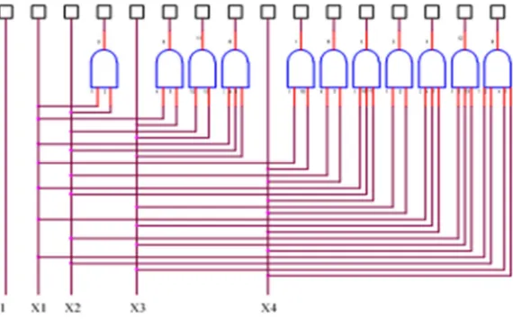
The extended input circuit is the foundation of the architecture of the proposed binary neural network and it is shown in Figure 1 below [1, 2]. This circuit extends the number of the original input neurons n to match the total number of all possible states 2n that these original inputs may assume. The extension of the dimensionality of the input space in order to achieve linearly separable patterns was first proposed by Cover [7]. These added neurons are connected to the original input neurons in such a way as to ensure the existence of the inverse of the extended input matrix and at the same time to make its derivation a simple task for any order or size of the extended input matrix. The extended input matrix, not only uses all possible combinations of the original inputs but also uses all possible input states 2n which represent all possible combinations of 1’s and 0’s used by any input pattern for a given number of original input neurons n. Thus the extended input matrix is a universal matrix and needs to be calculated only once for all applications. It is necessary to arrange the extended input neurons according to a simple rule [2] in order that the extended input matrix assumes an upper triangular matrix form. In the example given in figure 1 below, the input binary signal is applied to 4 original input neurons (at the bottom of Figure 1 below) and are incremented by steps of binary 1 from [0000]T to [1111]T.
Figure 1. The extended input circuit. At the bottom are shown 4 original input neurons (X1 the least significant bit to X4 the most significant bit) and a constant
input of binary 1. The extended input neurons, in this case 16 neurons, are shown at the top.
3. Input Module
This neural network is a single layer feed forward neural network. It converts the output of the previous extended input circuit (top of Figure 1) into a simple format or code to make minimum connections to the output module discussed next. It consists of a single layer feed forward neural network with linear adders that sum its weighted inputs. The function of the input module is to convert each of its input states into a signal with one and only one output neuron at binary 1 while all the rest are at binary 0. This is a kind of an encoder that converts input patterns into this simple code or format. It represents the minimum form of representing for any input pattern. It also uses minimum amount of energy expenditure for firing its output neurons.
If the output module uses the same signal format and converts its input signal back to the associated pattern then we need to make only one single connection from the one active output neuron of the input module (at binary 1) to one input neuron of the output module that produces the desired associated output pattern if a binary 1 is applied to it while all the other neurons are at binary 0. For the encoder output neurons we may choose only the first output neuron equals 1 and all the rest 0 for the first original input state [0000]T, only the second output neuron equals 1 and all the rest 0 for the second input state [1000]T and so on. Thus the output matrix of this input module becomes the identity matrix I, where each column of this matrix represents a state (or a vector) while the rows of each column represent the output neurons (top is least significant bit LSB):
Y = W X (1) where W represents the weight matrix and X is the input matrix of this module and Y is its output matrix. Since Y = I
then we get:
W = X-1 (2) For 4 original input neurons with states steadily increasing
from [0000]T to [1111]T with increments of binary 1 the number of the extended output nodes is 24. The extended input matrix and its inverse are given below [1, 2]:
1 1 1 1 1 1 1 1 1 1 1 1 1 1 1 1
0 1 0 1 0 1 0 1 0 1 0 1 0 1 0 1
0 0 1 1 0 0 1 1 0 0 1 1 0 0 1 1
0 0 0 1 0 0 0 1 0 0 0 1 0 0 0 1
0 0 0 0 1 1 1 1 0 0 0 0 1 1 1 1
0 0 0 0 0 1 0 1 0 0 0 0 0 1 0 1
0 0 0 0 0 0 1 1 0 0 0 0 0 0 1 1
0 0 0 0 0 0 0 1 0 0 0 0 0 0 0 1
0 0 0 0 0 0 0 0 1 1 1 1 1 1 1 1
0 0 0 0 0 0 0 0 0 1 0 1 0 1 0 1
0 0 0 0 0 0 0 0 0 0 1 1 0 0 1 1
0 0 0 0 0 0 0 0 0 0 0 1 0 0 0 1
0 0 0 0 0 0
X=
0 0 0 0 0 0 1 1 1 1
0 0 0 0 0 0 0 0 0 0 0 0 0 1 0 1
0 0 0 0 0 0 0 0 0 0 0 0 0 0 1 1
0 0 0 0 0 0 0 0 0 0 0 0 0 0 0 1
(3)
1
1 1 1 1 1 1 1 1 1 1 1 1 1 1 1 1
0 1 0 1 0 1 0 1 0 1 0 1 0 1 0 1
0 0 1 1 0 0 1 1 0 0 1 1 0 0 1 1
0 0 0 1 0 0 0 1 0 0 0 1 0 0 0 1
0 0 0 0 1 1 1 1 0 0 0 0 1 1 1 1
0 0 0 0 0 1 0 1 0 0 0 0 0 1 0 1
0 0 0 0 0 0 1 1 0 0 0 0 0 0 1 1
0 0 0 0 0 0 0 1 0 0 0 0 0 0 0 1
0 0 0 0 0 0 0 0 1 1 1
X−
+ − − + − + + − − + + − + − − +
+ − − + − + + −
+ − − + − + + −
+ − − +
+ − − + − + + −
+ − − +
+ − − +
+ −
=
+ − − 1 1 1 1 1
0 0 0 0 0 0 0 0 0 1 0 1 0 1 0 1
0 0 0 0 0 0 0 0 0 0 1 1 0 0 1 1
0 0 0 0 0 0 0 0 0 0 0 1 0 0 0 1
0 0 0 0 0 0 0 0 0 0 0 0 1 1 1 1
0 0 0 0 0 0 0 0 0 0 0 0 0 1 0 1
0 0 0 0 0 0 0 0 0 0 0 0 0 0 1 1
0 0 0 0 0 0 0 0 0 0 0 0 0 0 0 1
+ − + + −
+ − − +
+ − − +
+ −
+ − − +
+ −
+ −
+
(4)
In this case and according to Eq. (2) every entry of the inverse matrix X-1 represents the weight wi j between the
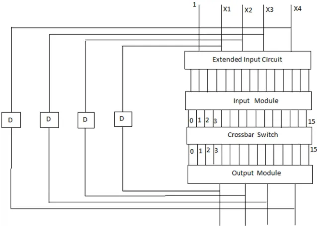
Figure 2. The architecture of the proposed extended-input binary neural network. The crossbar switch between input and output modules is the only circuit that needs to be trained for associating specific patterns at the original inputs (top of figure) and the output of the whole neural network (bottom of figure). Feedback with delay time D from output to the original input is added for some applications discussed below.
The rules by which we may deduce the inverse of the extended input matrix are as follows [1, 2]:
1. The extended input matrix and its inverse are both upper triangular matrices [8].
2. The extended input matrix and its inverse are symmetrical with respect to the diagonal perpendicular to the main diagonal (from lower left to upper right). 3. The sum of nonzero entries in each column of the
inverse matrix except the first column equals zero. The sum of nonzero entries in each row of the inverse matrix except the last row equals zero.
4. Every zero entry of the extended input matrix has a corresponding zero entry of its inverse and every entry equals 1 of the extended input matrix has a corresponding entry of its inverse with absolute magnitude of 1.
5. All entries of the main diagonal and every parallel diagonal above it of the inverse matrix have the same sign.
4. Output Module
This module is also a binary single layer feed forward neural network with output neurons as linear adders for weighted sum of its inputs. It is separated from the input module by a crossbar switch as shown in figure 2 above. It performs the opposite function of the encoder. Its input states may have only one neuron at binary 1 while all the rest are at 0 for each output patterns. Its output states are the desired patterns associated with the input patterns at the original inputs of the whole neural network. The input module converts an input pattern into a simple format or code and the output module converts back this simple format to the associated pattern or decode it according to the relation:
Y’ = W’ X’ (5) Here X’ is the input matrix of the output module. If we choose only the first input neuron of the output module at binary 1 to produce first output pattern, only the second neuron at binary 1 to produce the second pattern and so on, then the input matrix of the output module becomes the identity matrix: X’ = I and we get:
W’ = Y’ (6) The weight matrix is the same as the output matrix (each column is a vector or an output pattern). Thus all the nonzero weights of this output subnet have values of 1. The implementation of this subnet is very simple due to the equal values of all its weights.
In the example used above the output module has 4 output neurons similar to the original inputs and 16 input neurons. Thus for only the first input neuron of output module at 1 we get output pattern [0000]T, only the second neuron at 1 we get output pattern [1000]T, only the third neuron at 1 we get output pattern [0100]T, … and so on up to [1111]T. Here the top entry in each column is the least significant bit. Thus the weight matrix of the output module is a 4x16 matrix. All the weights are fixed and have no need to be adjusted by any learning process. To set one input neuron of the output module at binary 1 we connect it directly to the output neuron of the input module which is at binary 1. This is achieved by a crossbar switch discussed in the next section.
significant bit (LSB) to LSB, second bit to second bit up to the most significant bit (MSB) to MSB.
5. Interfacing Crossbar Switch and
Training
The training of the present neural network is confined to the process of finding the proper direct connection between one output neuron of the input module which represents a specific input pattern to one input neuron of the output module that produces an associated output pattern. This may be achieved by a crossbar switch that can connect any of these neurons. The semiconductor crossbar switches uses simple transistors as switches that can be turned on and off very fast to make these connections. In the example used above one end of the crossbar switch connects to one of the 16 output neurons of the input module and the other end to one of the 16 input neurons of the output module by choosing the proper transistor to switch on. Consequently the conducting path between these two modules transfers the high output of binary 1 between these two neurons. For some of the applications discussed below we require that the output neurons of the input module and the input neurons of the output module to be arranged in two parallel rows with increasing numerical values. Each pair of neurons facing each other represent the same pattern or binary number: first pair for original input and output patterns [0000]T (let us label both of them as neurons 0), second pair for pattern [1000]T (neurons 1), third pair for pattern [0100]T (neurons 2), and so on. We may arrange the inputs of the transistors of the crossbar switch in a table with rows representing output neurons of the input module and columns representing input neurons of output module. The transistor at the intersection of a row say x and a column say y will make a connection between an output neuron x of the input module corresponding to this row and an input neuron y of the output module corresponding to this column. For example the input of transistor (6, 9) (row 6 and column 9) will connect neurons representing binary input 5 and binary output 8, that make the pattern association 5→8 (we start counting from 0. This notation will be explained later.).
The use of one single connection between input and output modules using crossbar switch makes training for the association between any two patterns simple, fast and accurate. This may explain the extremely fast response in recognising a pattern (such as a face for example) by human biological neural networks provided that they contain similar architecture. It is well known that in the brain there are layers or sheets of parallel neuronal axons in each layer and these axons in adjacent layers run perpendicular to each other. This is similar to the lines used in crossbar switches [9].
The connections between input and output modules through the crossbar switch are not “hard-wired” but can easily be changed. The response of the network for a given stimulus is not inevitable but may be decided by a designer.
The two parallel rows of output neurons of the input
module and the input neurons of the output module and the connections between them resemble the double helix and the bases crossing them from one strand to the other in a DNA macromolecule. The sequence of these bases connecting these two parallel backbone strands is the fundamental structure for life. Similarly the proper connections between the two rows of neurons of input and output modules of the present architecture of the artificial neural network contain the desired information and knowledge. However, as we have seen that the number of the neurons of input and output modules and the connections between them for n original inputs is 2n. For n=30 we get a number of connections in the order of 109. The DNA macromolecules has similarly large number of bases of the same order of magnitude yet a great progress has been made in understanding many of its functions and tremendous benefits have been gained from this knowledge. Similarly the emulation of small part of the complexity of the brain using artificial neural networks will help to improve our knowledge of some of its functions and provides some useful application (see below).
6. The Brain and the Mind
made of two parallel metallic plates with the space between them filled with a dielectric material. If we charge one of these two plates with positive charge say, then an electric field will be established between these two plates starting from the positive charges and terminates with an equal and opposite (negative) charge on the other plate.
The excitation of output neurons of input module due to a stimulus will result in the spread of an electric field in the narrow gap between this module and output module. This field may be capable of exciting one or several input neurons of the output module which results in a response but of more global character. The stimulus in this case will not be a one-to-one process since the field is not localized and spread over many neurons of the output module but it will be a one-to-many relation. Also the response time must be much faster than the physical link between input and output modules with slow action potentials propagating in this link since the electrical field travels with the speed of light. Moreover a time varying excitation of the output neurons of the input module will result in the propagation of electromagnetic waves in the gap between input and output modules. These waves may be the origin of the well known brain waves which are linked to thought and mental processes. By this field hypothesis a modification of the materialist theory of the mind [13] is introduced in order to bridge the gap (or chasm) between the brain and the mind.
7. Applications
It is quite obvious that switching a transistor is a much faster process compared to loading a register or modifying its content. Consequently the present neural network is expected to be faster than a corresponding register machine which is the prototype of all digital computers. The most direct application of this neural network is to reproduce or copy the input pattern to the output. This function is displayed in biological neural networks due to the spatial close proximity of each of the pairs of neurons of the input (sensor) and output (motor) modules that represent the same pattern. Thus one of the output neurons of the input module can easily excite the closest input neuron of the output module which represents the same pattern (or binary value). If we use feedback as shown in Figure 2 above then this network can be used as a dynamic memory device that stores indefinitely the same pattern when the input pattern is removed. The output pattern will be continuously refreshed and available at the outputs of this neural network. The capacity of this memory for n original inputs is 2n a much higher capacity than some associative memories [5]. To carry further the analogy with the DNA macromolecule mentioned above, this network may be considered to replicate or transcribe the original pattern from the input to the output indefinitely.
The logical principle (conditional) that corresponds to pattern association (without feedback) is: if A then B, where A is the input and B is the output of the whole network. Consider this circuit first without feedback. It acts as a memory device: the address is the input A and the content of
this memory at this address is the output B. There is no special memory space that stores the contents of this memory. The crossbar switch is used to select only one output from all possible outputs that corresponds to the memorised content of the input address. Thus this crossbar switch settings contains all the information needed to recall this memory. As a collection of switches the crossbar switch resembles the thalamus in the brain which acts as a relay center.
The following notation is used for connecting the crossbar switches to associate input and output patterns: the output neuron of the input module is represented by a first number and the input neuron of the output module is represented by a second number with the connection between them represented by an arrow. Thus in the case of the above copy function the following connections are used: 0→0, 1→1, 2→2, 3→3,…etc. In this case the transistors along the main diagonal of the transistor table of the crossbar switch mentioned above will be the only transistors turned on.
This neural network may also be used to perform addition and subtraction. Consider the following operation: 5+3. In this case the binary input 5 or [1010] is applied to the original inputs (top of Figure 2 above), where the left digit is the LSB. The output neuron 5 of the input module will be asserted high (1). The crossbar switch 5→5 is set by selecting the transistor (6, 6) (6th row and 6th column in transistor table, counting 0). The other part of this operation, namely +3 is translated as an instruction to activate the transistor at location 3 places to the right of the first transistor on the same row of the transistor table (6, 9) to represent the connection 5→8. Thus an input of binary 5 will result in an output of binary 8. Similarly in the operation 5-3 the transistor at location in the table three places to the left of first transistor is activated (6, 3) on the same row to make the connection (5→2): input 5 gives an output 2.
The multiplication operation uses the same procedures by repeated addition. For example 5x3:start by choosing transistor at table location (6, 6) as before and shift twice horizontally on the same row with each shift equals 5 places to location (6, 16) to produce 5→15: input=5 and output=15. In general for mxn start by (m+1,m+1) location on transistor table and jump on the same row n-1 times with each jump=m
places to the right. These jumps are achieved by address jumps in the memory space of these transistors.
Periodic functions may be produced similarly. This function is similar to rhythmic phenomena such as regular heart beat in biological organisms. In this case the above series is modified to become: A→B^B→C^C→D^D→F^F→A^ A→B....etc. where the symbol ^ represents feedback. Thus this series repeats itself indefinitely. The variations of the periodic time in these phenomena may be achieved by changing the delay time D in the feedback loop shown in Figure 2 above.
time less than the delay time D.
In this article only 4 original inputs are used as an illustration for the extended input binary neural network. This number may be extended to more original inputs (for example 16 or more) without much difficulty. However another approach may be applied similar to the multiplexing techniques used extensively in digital computers. Consider an image made up of 4X4 squares. Each square may be black (binary 1) or white (binary 0). Apply each row (4 original inputs) to the network discussed above at a time. In each time one output neuron of the input module is asserted high. However in order to identify all 4 rows (16 inputs) as a one single pattern or image (one neuron high) latches may be used as well as 4-input AND gates. Each time an output neuron of the input module is made high by 4 original inputs in a row of the image it is latched and remains high at the latch’s output even when the original inputs are removed. When all of the 4 rows of the image are applied in sequence the corresponding 4 outputs of the latches are fed to the inputs of a 4-input AND gate. Thus the output of the 4-input AND gate becomes high. This is the code for the 4X4 image. Thus to extended the 4 original inputs to 16 inputs a layer of latches and multi-input AND gates should be inserted between the input module and the crossbar switch.
8. Conclusions
The proposed architecture of a neural network is inspired by the structure and function of the brain. Although it is impossible to duplicate (or understand) the great complexity of the brain as a whole yet it is very useful and instructive to imitate some of the brains structures. Thus the input signal is processed first by the extended input circuit then sent to the input module to be converted to a simple code. The output module receives this simple code after it is properly diverted to its proper inputs by a crossbar switch. These two modules have fixed weights that can be deduced directly due to the use of the extended input circuit. It is shown that the nonzero weights of the input module take only two values, +1 and -1, similar to the excitatory and inhibitory synapses in biological neural networks. The only two values of weights reduce the almost infinite range of continuous and unknown weights between input and output neurons usually calculated by error criteria such as cost functions and by iteration techniques. The direct connection between input and output modules using a single connection by the crossbar switch for each pair of input and output patterns speeds up the response of the network and ensures that the output pattern is produced accurately. The capacity of this neural network when used as a memory device, (with an original n input neurons), is 2n a much greater capacity than other neural networks used for pattern association.
The training process of the present neural network is not a process of adjusting the synaptic connections among all neuron in the network but rather by turning on and off the transistors of the crossbar switch which connects and disconnects the output neurons of the input module and the input neurons of the output module. Thus the process of
training becomes much more accurate and faster.
The present neural network is used in several applications such as: pattern association and as a memory device. It can also be used to generate periodic functions and also for logical and mathematical operations such as conditional logic, addition, subtraction and multiplication.
The number of original inputs (the dimensionality) of this neural network may be increased significantly by multiplexing the original inputs and using latches and multi-input AND gates between input module and the crossbar switch.
The role of the crossbar switch is generalized by postulating the presence of an electric field which mediates between input (stimuli) and output (responses) regions of the brain. Consequently the brain is viewed as the input and output neural networks that transform input stimuli into simple codes and then convert back these codes to output responses. The mind on the other hand is the global field that selects the response which is appropriate to match each of the input stimuli.
References
[1] Wassef, W. A., 2002, Extended Input Neural Network: Applications, Implementation and Learning, Neural Parallel & Scientific Computations, vol. 10, issue 4, pp. 387-410. Dynamic Publishers, Inc. GA.
[2] Wassef, W. A., 2012, Time Series Prediction and Hardware of the Extended Input Neural Network (EINN), Neural, Parallel & Scientific Computations, vol. 20, issue 3/4 pp. 475-482, Dynamic Publishers, Inc. GA.
[3] Bisi,M. And Goyal, N. K., 2017, Artifical Neural Network Applications for Software Reliability Prediction, Wiley-Scrivener, NY USA.
[4] Kosko, B., 1987, Adaptive Bidirectional Associative Memories, Applied Optics, vol. 26, no. 23, pp. 4947–4960. [5] Kosko, B., 1992, Neural Networks and Fuzzy Systems,
Prentice Hall, Englewood Cliffs, NJ, USA.
[6] Glesner, M. And Puchmuller, W., 1994, Neurocomputer, An Overview of Neural networks in VLSI. Chapman and Hall, Hew York, USA, pp. 192–198.
[7] Cover, T. M., 1965, IEEE Transactions on Electronic Computers 14, pp. 326-334.
[8] Anton, H., 2000, Elementary Linear Algebra, 8th ed. John Wiley & Sons, New York, p. 68.
[9] Kurzweil, R., 2012, How to Create a Mind, Viking, Published by the Penguin Group Inc., N.Y., USA, pp. 84-85.
[10] Smythies, J. R., 2014, Brain and Mind: Modern Concepts of the Nature of Mind, Rotledge, N.Y, USA.
[11] Wilkinson, R., 2013, Minds and Bodies, Rotledge, N.Y. USA. [12] Carter, M. 2007, Minds and Computers, An Introduction to
the Philosophy of Artificial Intelligence, Edinburgh University Press, Edinburgh, UK, p. 36.