RESEARCH ARTICLE
Position and inclination control of a
passive disk based on cyclic motion generation
Tadayoshi Aoyama
1*, Qingyi Gu
2, Takeshi Takaki
1and Idaku Ishii
1Abstract
We propose a position and inclination controlling method for a passive object using an active plate. Previously, we proposed a novel manipulation scheme that can control a passive object’s orientation using an active plate. In the work, stable plate cyclic motion is designed and inclination control of the object is realized. However, the object’s position is not considered, so there is a possibility that the object could move. Using our plate trajectory design we can control not only the passive object’s inclination but also its position. We verify that the designed plate motion can control both the object’s inclination and its position through dynamics simulation. A stability analysis around a fixed point is conducted using a Poincaré return map, demonstrating that fixed points are asymptotically stable.
Keywords: Cyclic motion, Nonlinear discrete system, Manipulation
© The Author(s) 2017. This article is distributed under the terms of the Creative Commons Attribution 4.0 International License (http://creativecommons.org/licenses/by/4.0/), which permits unrestricted use, distribution, and reproduction in any medium, provided you give appropriate credit to the original author(s) and the source, provide a link to the Creative Commons license, and indicate if changes were made.
Background
Rhythmic motion control has been an important research topic studied for many years in robotics and mechatronics [1–18]. Legged locomotion is one type of rhythmic motion that requires cyclic stability. A simple hopping robot using a leg composed of a double-acting air cylinder was built, and completely dynamic, stable hopping locomotion was realized [1]. The designed con-troller can handle hopping motion, forward speed, and body upright attitude. Koditschek et al. theoretically ana-lyzed the motion of Raibert’s hopping robot [1] by using simplified models of the hopping robot [2]; it has been confirmed that the modeled properties match those of Raibert’s physical data. A three-dimensional (3-D) biped walking controller that ensures cyclic stability based on passive dynamic autonomous control (PDAC) [19] was proposed, and 3-D biped walking using an actual robot was realized [3]. Moreover, the adaptability of the cyclic motion to terrain has been analyzed, and 3-D biped walk-ing on nonflat terrain was realized experimentally [4].
Juggling is also a task that requires cyclic stability with dynamic dexterity. Koditschek’s group has been studying
robotic juggling for many years [5–8]. Bühler et al. pro-posed a mirror algorithm from their successful experi-ments that can determine the trajectory of a robot paddle as mirrored [5]. A robot that can juggle up to two pucks was realized by using the feedback strategy of the mirror law. In addition, the proposed algorithm was developed further and juggling and catching of two objects has been experimentally realized [6]. The mirror law was modi-fied for spatial two-object juggling and the algorithm was verified through experiment using a three-degrees-of-freedom robotic arm along with a real-time stereo cam-era system [7].
Some research groups have proposed nongrasping manipulation schemes using an active plate, which also require cyclic stability [9–17]. Senforless positioning and orientation adjustment have been realized using a flexible vibrating plate [9]. The vibrating plate is able to create a two-dimensional programmable force field and generated sequences of force fields. A vibratory transport mecha-nism using an active plate was proposed by Umbanhowar and Lynch, and the transportation behavior was verified through experiments using a vibrating plate [10]. Vose et al. analyzed the bang-bang motion of a rigid plate and derived the generation of nodal lines; the analysis results were verified through comparison between numeri-cal simulation results and experimental results obtained
Open Access
*Correspondence: [email protected]‑u.ac.jp
1 Department of System Cybernetics, Hiroshima University, 1‑4‑1,
Kagamiyama, Higashi‑Hiroshima 739‑8527, Japan
from an experimental active plate system with six degrees of freedom [11]. In addition, a mechanism to predict the relationship between the small-amplitude cyclic motion of a six-degrees-of-freedom rigid plate and its velocity field, called asymptotic velocity theory, has been devel-oped [12]. The importance of the asymptotic velocity for characterizing plate motion was verified through simulations and experiments. Ronsse et al. proposed and experimentally verified sensorless stabilization of bounce juggling based on a stabilization analysis in rhythmic tasks using a wedge billiard [13]. Furthermore, a robust closed-loop control scheme for periodic patterns in a pla-nar juggler, which needs only impact times as the feed-back state, was proposed by Ronsse et al. [14]. Inspired by the handling mechanism of a pizza chef, Higashimori et al. [15, 16] developed a manipulation device using a plate that can control an object on it to a desired posi-tion and orientaposi-tion through visual feedback. Reist and D’Andrea [17] designed Blind Juggler, which can juggle a ball at a height of 2 m without feedback, and analyzed the local stability of the ball trajectory. Although non-grasp manipulation can generally result in efficient manipula-tion for all the aforemenmanipula-tioned manipulamanipula-tion schemes using plates, the controlled objects are represented by a mass point or a two-dimensional rigid body. Moreover, an object’s motion in the direction of the gravitational force has not been considered. We worked towards devel-oping an efficient non-grasp manipulation scheme using an active plate. This paper contributes to our final goal of non-grasp manipulation by working on unrealized issues regarding non-grasp manipulation when using plates.
We previously proposed a novel manipulation scheme that can control a passive object’s orientation in the direction of the gravitational force using an active plate and realized hitherto unrealized object motion [18]. In that work, stable plate cyclic motion was designed and the inclination control of the object was realized. How-ever, the object’s position was not considered in that work so that the problem establishment is set simple. Therefore, there was a possibility that the object could move. In addition, while the stability analysis in [18] was based on linearization around fixed points, its accu-racy was not sufficient. Thus, in this study, we propose a manipulation method using a plate to control not only the passive object’s inclination, but also its position. In addition, the stability analysis is conducted with a high degree of accuracy by deriving the Poincare return map, which is not an approximate approach. In this work we consider a planar rigid tumble doll as a controlled object and the cyclic plate trajectory is designed to achieve both inclination and position control. Then, we verify that the designed plate motion can control both the object’s
inclination and its position through dynamics simulation. A stability analysis around a fixed point is conducted using a Poincaré return map, demonstrating that fixed points are asymptotically stable.
Methods Cyclic motion
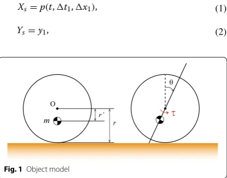
In this study, we define the object as a tumble doll that is a planar, rigid sphere, as shown in Fig. 1. θ is the angle of inclination from the stable posture. This rigid model gen-erates a restorative force τ =mgr′sinθ when the object
is inclined by θ from the stable point, where, m, g, and r′
denote the object’s mass, gravitational acceleration, and the distance from the center of the sphere to the center of mass (CoM), respectively. The rigid model tumble doll is inherently stable without any input owing to the restora-tive force.
A system composed of a passive object and an active plate is defined as the discrete dynamical system used herein. The motion of this system is designed to be cyclic, with one cycle of the designed motion divided into four phases, as shown in Fig. 2: (i) a rolling phase, (ii) a hop phase, (iii) a flight phase, and (iv) a collision phase. The plate is moved to maintain the desired orientation of the object in appearance by designing the motion of each phase to be of a short duration.
Plate trajectory and dynamics
To this end, it is assumed that slip does not occur dur-ing any phase. To describe the position of the object, the local coordinate system {1} is set at the plate.
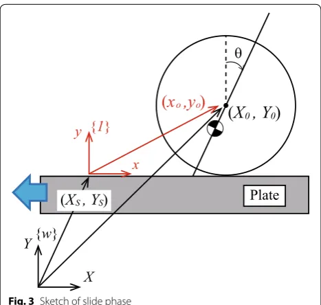
Rolling phase
The objective of the rolling phase is to incline the object (Fig. 3). The plate trajectory of the rolling phase in the world coordinate system is generated as follows:
(1)
Xs=p(t,�t1,�x1),
(2)
Ys=y1,
r’ r m
O
θ
τ
where Xs and Ys denote the position of the stage in the
world coordinate system {w}, x1 is the moving distance
of the plate in the rolling phase, t1 is the moving time
of the plate in the rolling phase, p(t,�t1,�x1) is a
fifth-order polynomial trajectory function of t that connects moving distance x1 at moving time t1, and y1 is a
con-stant value.
The dynamics around the object center of the rolling phase in coordinate {1} is derived as follows:
where xo and yo denote the position of the object in the
local coordinate system {1}, fr is the friction force of
the rolling phase, Nr is the normal force, I is the object’s
moment of inertia around the CoM, and r is the object’s radius. If slip does not occur, the position of the object can be described as
(3)
mx¨o= −mX¨s−fr,
(4)
my¨o=Nr−mg,
(5)
Iθ¨= −mgr′sinθ+mX¨
sr′cosθ−rfr,
(6)
xo =rθ+xinio (r), where
xini(r)o is the initial position of the rolling phase.
From Eqs. (3), (5), and (6), θ can be expressed as
e s a h p p o H ) ii ( e
s a h p g n il l o R ) i(
(iii) Flight phase (iv) Collision phase
θ
θ
θ
θ
Fig. 2 Phases of cyclic motion
θ
Plate
x
y
{1}
{
w
}
X
Y
(
X , Y
0 0)
(
X , Y
S S)
(x ,y )
o owhere C11 and C12 are integral constants.
Finally, the object position Xo of the rolling phase in the
world coordinate system is expressed as follows:
Hop phase
The objective of the hop phase is to toss the object up in the air (Fig. 4). The plate trajectory of the hop phase in the world coordinate system is generated as follows:
where x2 is the moving distance of the plate in the
roll-ing phase, t2 is the moving time of the plate in the
roll-ing phase, and p(*, *, *) is the same fifth-order polynomial trajectory function used in the rolling phase.
The dynamics around the object center in the hop phase in coordinate {1} is derived as follows:
(7)
¨
θ = 1
I+mr2
−mgr′sinθ+
r′cosθ−r mX¨s
:=f1(θ,X¨s),
(8) ˙
θ =
f1(θ,X¨s)dt+C11,
(9)
θ =
f1(θ,X¨s)dt+C11t+C12,
(10)
:=g1(X¨s)
(11) Xo=Xs+rθ+xinio (r)
(12)
=Xs+rg1(X¨s)+xoini(r)
(13)
Xs=p(t,�t2,�x2),
(14) Ys=p(t,�t2,�y2),
(15)
mx¨o= −m
¨
Xs 2
+ ¨Ys 2
cosφ−fh,
where fh is the friction force of the hop phase, Nh is the
normal force, and φ is the angle that specifies the moving
direction of the plate. If slip does not occur, the position of the object is described by xo=rθ +xoini(h) using the initial
position of the hop phase, which is the same as for the rolling phase. Thus, from Eqs. (15) and (17), θ can be expressed as
where C21 and C22 are integral constants.
Finally, the object position Xo of the rolling phase in the
world coordinate system is expressed as follows:
Flight phase
The motion in the flight phase is a simple free-fall motion (Fig. 5). In the flight phase, the plate motion is generated in order to adjust the position of the controlled object. The dynamics around the object center in the flight phase is expressed as follows:
θ can be expressed as
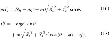
(16)
my¨o=Nh−mg−m
¨ Xs
2 + ¨Ys
2
sinφ,
(17)
Iθ¨= −mgr′sinθ
+m
¨ Xs
2
+ ¨Ys
2
r′cos(θ+φ)−rfh,
(18)
¨
θ = −mgr
′sinθ
I+mr2
+m
¨ Xs
2 + ¨Ys
2
I+mr2
r′cos(θ+φ)−rcosφ
(19) :=f2(θ,a2),
(20) ˙
θ =
f2(θ,
¨
Xs
2
+ ¨Ys
2
,φ)dt+C21,
(21) θ =
f2(θ,
¨
Xs 2
+ ¨Ys 2
,φ)dt+C21t+C22
(22) :=g2 ¨ Xs 2 + ¨Ys
2
,
(23) Xo=Xs+rθ+xinio (h)
(24)
=Xs+rg2
¨ Xs
2
+ ¨Ys
2
+xinio (h).
(25) mx¨o=0,
(26)
my¨o= −mg,
(27)
Iθ¨=0.
(28) ¨
θ =0, θ
Plate
x y {1}
{w}
X Y
(X , Y 0 0)
(X , Y )S S
(x ,y )o o
φ
where C31 and C32 are integral constants.
The position of the object is described as follows:
We can obtain the position of the object from Eq. (31). The plate position is adjusted according to the position of the object during the flight phase. The plate trajectory of the hop phase in the world coordinate system is gen-erated according to the position of the object during the flight phase, so
where x3 and t3 are the moving distance and time,
respectively, of the plate in the rolling phase.
t3 and x3 are determined as follows:
(29) ˙
θ =C31,
(30)
θ =C31t+C32,
(31)
xo =C33t+C34.
(32)
Xs=p(t,�t3,�x3),
(33) Ys=p(t,�t3,�y3),
(34) �t3= y˙
ini
o +
(˙yini
o )2+2g�y2
g ,
(35)
�x3= ˙xinio �t3+α,
where xinio (f) and yini(fo ) the initial position of the flight
phase, α is a constant value.
Finally, the object position Xo of the rolling phase in the
world coordinate system is expressed as follows:
Collision phase
By assuming a completely inelastic collision at landing (Fig. 6), the object’s angle and its angular velocity in the horizontal direction are conserved during the collision, and the angular velocity in the vertical direction dissi-pates. The non-elastic collision model is used in previous plate manipulation works (e.g. [13, 14, 17, 18]). Then, the following velocity exchange takes place:
where θ+, θ˙+, θ−, and θ˙− denote the angle just before the
collision, the angular velocity just before the collision, the angle just after the collision, and the angular velocity just after the collision, respectively.
Results and discussion Dynamics simulation
In this section, we confirm whether the designed plate cyclic motion can control not only orientation of the con-trolled object but also its position. In this simulation, the calculations were performed using the derived dynam-ics in this paper, and the object and plate were drawn in
(36)
Xo=Xs+xo.
(37)
θ+ ˙ θ+
=
θ− ˙
θ−cos2θ−
(38)
:=�(v−),
g
θ
Plate
x
y
{1}
{
w
}
X
Y
(
X , Y
0 0)
(
X , Y
S S)
(
x ,y
o o)
Fig. 5 Sketch of flight phase
Instantaneous
collision
θ
Plate x
y {1}
{w}
X Y
(
X , Y
0 0)
(
X , Y
S S)
(
x ,y
o o)
an OpenGL environment. The simulation model and environment is same as our previous work [18], thereby matching the experimental results. For analysis, because the objective of this study is to maintain the states in which the object is inclined at a specified position, the state vector is composed of the object angle and position
v= [θ,Xo]. In addition, the discrete state vector is defined
as vk = [θ[k],Xo[k]]T, which is just after the kth collision
of the state vector. The fixed points of the state vector are searched by trial and error through parameter adjustment in this research. The parameters of the object and active plate were set to m= 0.3 kg, r= 0.05 m, r′= 0.03 m, t
1=
0.1 s, x1= 0.03 m, t2= 0.03 [s], x2= 0.005 m, y2=
0.0495 m, α= 0.0002 m, and φ= 85°. The initial conditions
of the controlled object were set to θ= 0.0° and θ˙= 0.0°,
and the stage’s initial position (Xs,Ys) was set to (0.0, 0.7).
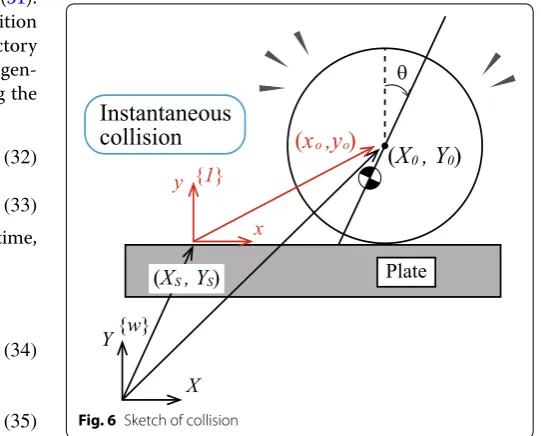
Figures 7 and 8 show each component of
vk = [θ[k],Xo[k]]T, respectively. Figures 7 and 8
con-firm that the object’s angle θ and position Xo converged
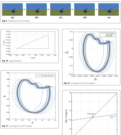
to a fixed value. Furthermore, the results indicate that the object motion had cyclic stability and that the object angle and position were controlled. Figure 9 shows snap-shots of the simulation after convergence. Each snapshot shows the state immediately after collision. It is visually confirmed that the inclination angle and position of the controlled object are stably converged. In this simulation, the stage produced the cyclic motion trajectory shown in Fig. 10. It is confirmed that the stage trajectory settles to a unique trajectory.
The objective of this dynamic simulation is to confirm whether the proposed control scheme can simultane-ously control the inclination and position of a passive object. The controllable range of the controlled object depends on the type of hardware system used. Thus, this issue is left for a future experimental study, where a hard-ware system will be specified and implemented.
Orbital stability analysis
In this section we investigate the orbital stability of the designed cyclic motion. First, we evaluate the conver-gence. Figures 11 and 12 show the phase portrait of θ and Xo when a disturbance is added. As shown in Fig. 11, if
the value of θ is either higher or lower than the desired
value, θ converges to the desired state. Similarly, if the
value of Xo is either higher or lower than the desired
value, Xo converges to the desired state, as shown in
Fig. 12.
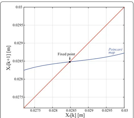
Next, the stability of a fixed point is investigated by using a Poincaré map. By defining the vector function ξ
according to Eqs. (10), (12), (22), (24), (30), (36), and (38), the Poincaré map is ginven as
Let v∗= [θ∗,Xo∗]T be a fixed point of the discrete system
described by Eq. (39); then, the discrete system converges as follows:
Figures 13 and 14 show the Poincaré map of θ and Xo ,
respectively. Since both slopes on the Poincaré map are less than 1, it is confirmed that the fixed point θ∗ and Xo∗
generated by the designed cyclic plate motion is asymp-totically stable.
Conclusions
We proposed and tested an active-plate-based method for manipulating the posture angle and position of a rigid object. The active-plate motion was designed to be cyclic and can control both position and inclination angle of the controlled object. A test object was subjected to the designed cyclic motion, and the proposed approach was then verified through dynamics simulation. Finally, the
(39)
v
k+1=ξ(vk,�t1,�x1,�t2,�x2,�y2,φ).
(40)
v∗=ξ(v∗,�t1,�x1,�t2,�x2,�y2,φ).
Cycle
0 10 15 20 25 30 35 40 45 50
θ
[
k
] [deg
]
-10 0 10 20 30 40 50 60
5
Fig. 7 Transition of θ[k]
Cycle
0 10 15 20 25 30 35 40 45 50
X
o
[
k
] [m
]
-0.01 0 0.01 0.02 0.03 0.04 0.05
5
stability of a fixed point was analyzed on a Poincaré map, confirming the asymptotic stability of the system.
(a) (b) (c) (d) (e)
Fig. 9 Snapshots of the simulation
Xs [m]
-0.03 -0.02 -0.01
Ys
[m
]
0.698 0.699 0.700 0.701 0.702 0.703 0.704 0.705 0.706
0.01 0.02 0.03 0.04
0
Fig. 10 Stage trajectory
θ
27 28 29 30 31 32 33 34
-200 -150 -100 -50 0 50 100 150
θ
Convergent trajectory
Fig. 11 Convergence result for angle
X
o0.023 0.024 0.025 0.026 0.027 0.028 0.029 0.03 -0.15
-0.1 -0.05 0 0.05 0.1
X
o
Convergent trajectory
Fig. 12 Convergence result for position
θ[k] [deg]
31.5 32 32.5 33 33.5 34
31.5 32 32.5 33 33.5 34
θ [k+1] [deg/s]
Poincaré map Fixed point
Authors’ contributions
TA carried out the main part of this study and drafted the manuscript. QG, TT, and II contributed concepts and revised the manuscript. All authors read and approved the final manuscript.
Author details
1 Department of System Cybernetics, Hiroshima University, 1‑4‑1, Kagamiy‑
ama, Higashi‑Hiroshima 739‑8527, Japan. 2 Research Center of Precision
Sensing and Control Institute of Automation, Chinese Academy of Sciences, 95 Zhongguancun East Road, Beijing 100190, China.
Acknowledgements
This research was partly supported by the Research Foundation for the Elec‑ trotechnology of Chubu.
Competing interests
The authors declare that they have no competing interests.
Received: 24 June 2015 Accepted: 7 December 2016
References
1. Raibert MH (1986) Legged robots that balance. MIT Press, Cambridge 2. Koditschek DE, Buehler M (1991) Analysis of a simplified hopping robot.
Int J Robot Res 10(6):587–605
3. Aoyama T, Hasegawa Y, Sekiyama K, Fukuda T (2009) Stabilizing and direc‑ tion control of efficient 3‑D biped walking based on PDAC. IEEE Trans Mechatron 14(6):712–718
4. Aoyama T, Sekiyama K, Hasegawa Y, Fukuda T (2012) PDAC‑based 3‑D biped walking adapted to rough terrain environment. J Robot Mechatron 24(1):37–46
5. Bühler M, Koditschek DE, Kindlmann PJ (1990) A family of robot control strategies for intermittent dynamical environments. IEEE Control Syst Mag 10(2):16–22
6. Buehler M, Koditschek DE, Kindlmann PJ (1994) Planning and control of robotic juggling and catching tasks. Int J Robot Res 13(2):101–118 7. Rizzi AA, Koditschek DE (1993) Futher progress in robot juggling: the
spatial two‑juggle. In: Proceedings of the IEEE international conference on robotics and automation. pp 919–924
8. Rizzi AA, Koditschek DE (1994) Futher progress in robot juggling: solvable mirror laws. In: Proceedings of the IEEE international conference on robotics and automation. pp 2935–2940
9. Böhringer K‑F, Bhatt V, Donald BR, Goldberg K (2000) Algorithms for sen‑ sorless manipulation using a vibrating surface. Algorithmica 26:289–429 10. Umbanhowar P, Lynch KM (2008) Optimal vibratory stick‑slip transport.
IEEE Trans Automat Sci Eng 5(3):537–544
11. Vose TH, Umbanhowar P, Lynch KM (2009) Friction‑induced lines of attraction and repulsion for parts sliding on an oscillated plate. IEEE Trans Automat Sci Eng 6(4):685–699
12. Vose TH, Umbanhowar P, Lynch KM (2009) Friction‑induced velocity fields for point parts sliding on a rigid oscillated plate. Int J Robot Res 28(8):1020–1039
13. Ronsse R, Lefèvre P, Sepulchre R (2006) Sensorless stabilization of bounce juggling. IEEE Trans Robot 22(1):147–159
14. Ronsse R, Lefèvre P, Sepulchre Rodolphe (2007) Rhythmic feedback control of a blind planar juggler. IEEE Trans Robot 23(4):147–159 15. Higashimori M, Utsumi K, Kaneko M (2008) Dexterous hyper plate
inspired by pizza manipulation. In: Proceedings of the IEEE international conference on robotics and automation. pp 399–406
16. Higashimori M, Utsumi K, Omoto Y, Kaneko M (2009) Dynamic manipulation inspired by the handling of a pizza peel. IEEE Trans Robot 25(4):829–838
17. Reist P, D’Andrea R (2012) Design and analysis of a blind juggling robot. IEEE Trans Robot 28(6):1228–1243
18. Aoyama T, Harada Y, Gu Q, Takaki T, Ishii I (2015) Cyclic motion design and analysis for a passive object manipulation using an active plate. Adv Robot 29(7):493–503
19. Doi M, Hasegawa Y, Fukuda T (2004) Passive dynamic autonomous control of bipedal walking. In: Proceedings of the IEEE‑RAS international conference on humanoid robots. pp 811–829
X0[k] [m]
0.0275 0.028 0.0285 0.029 0.0295 0.03 0.0275
0.028 0.0285 0.029 0.0295 0.03
Poincaré map Fixed point
X
0[k+1] [m
]
![Fig. 8 Transition of Xo[k]](https://thumb-us.123doks.com/thumbv2/123dok_us/889793.1586396/6.595.306.540.87.223/fig-transition-of-xo-k.webp)